Table of Contents
Advertisement
Advertisement
Table of Contents

Related Manuals for Endress+Hauser Analytik Jena CyBio SELMA


Summary of Contents for Endress+Hauser Analytik Jena CyBio SELMA
- Page 1 ® CyBio SELMA User Manual...
- Page 3 © Copyright Copyright 2016 Analytik Jena AG All rights reserved. No part of this documentation may be duplicated, photocopied, saved to a storage system or transferred to electronic media without prior written permission of the publisher. Publisher Analytik Jena AG Konrad-Zuse-Strasse 1 07745 Jena Germany Tel: +49 3641 77 70 Fax:+49 3641 77 9279 Service Support Tel: +49 3641 77 9449 E-Mail: service.cybio@analytik-jena.de Ordering number OL7001-26-21XBLE05 Document type Translation of the original User Manual Serial number Refer to nameplate at the product Registered trademarks: ® CyBio ........Analytik Jena AG, Germany Title to all other trademarks or brands which are referenced in this User Manual belongs ...
- Page 5 EG Konformitätserklärung EC Declaration of Conformity Name und Anschrift des Herstellers: Name and address of the manufacturer: Analytik Jena AG Konrad-Zuse-Straße 1 D-07745 Jena Hiermit erklären wir, dass das nachstehend beschriebene Produkt Herewith we declare, that the product described below ®...
- Page 6 ® 2016 CyBio SELMA...
-
Page 7: Table Of Contents
Table of contents General Information ..........1 Notes Regarding This User Manual ... - Page 8 4.1.6 External Display . . . . . . . . . . . . . . . . . . . . . . . . . . . . . . . . . . . . . . . . . . . 20 Operating Modes . . . . . . . . . . . . . . . . . . . . . . . . . . . . . . . . . . . . . . . . . . . . 21 4.2.1 Operation in Sitting Position. . . . . . . . . . . . . . . . . . . . . . . . . . . . . . . . . . 21 4.2.2 Operation in Standing Position. . . . . . . . . . . . . . . . . . . . . . . . . . . . . . . . 21 Product Versions . . . . . . . . . . . . . . . . . . . . . . . . . . . . . . . . . . . . . . . . . . . . . 21 Function . . . . . . . . . . . . . . . . . . . . . . . . . . . . . . . . . . . . . . . . . . . . . . . . . . . 22 Transportation & Storage ........23 Transportation ...
- Page 9 Precision Performance (Pipetting Head) . . . . . . . . . . . . . . . . . . . . . . . . . . . . 72 Fault Removal ..........75 Faulty Value Entries ...
- Page 10 ® 2016 CyBio SELMA...
-
Page 11: General Information
General Information General Information Notes Regarding This User Manual This User Manual informs about the setup and function of the ® CyBio SELMA. It provides qualified operating personnel with the knowledge that is required to handle the system in a safe manner. It also contains advice regarding system maintenance and care and explains potential causes and action for removal of malfunctions. You should always keep this User Manual within easy reach of the system. This Manual must be readily available to operating and maintenance personnel at any time! This User Manual is an integral part of the system and must be handed over to the next system owner or user as may be appropriate if there is a change on ownership. NOTE All data and information provided herein reflect the latest state of knowledge available at the moment of publishing. Analytik Jena AG reserves the right to make changes if deemed necessary and appropriate in the interest of technical change. Target Group This User Manual addresses: Qualified expert personnel having completed a special training on system opera- tion and maintenance ( refer to “Requirements On Operating Personnel” on page 11). Personnel responsible for the planning of procedural sequences, maintenance and cleaning work, safety precautions, etc. -
Page 12: Conventions
General Information Conventions 1.3.1 Warning Notes/Warning Signs WARNING Designates a potentially dangerous situation that may result in death or severe injury unless prevented. CAUTION Dangerous situation! Potential consequences: slight or minor injuries. NOTICE Designates a potential danger or a situation that may result in material damage. 1.3.2 Important Information NOTE Useful operator advice, involves no hazardous situation. NOTE Notes regarding environmental protection ® 2016 CyBio SELMA... -
Page 13: Conforming Use
General Information Conforming Use NOTE All preventive measures are coordinated with the conforming use of the equipment. Non-conforming use may cause loss of protection. The owner/operator will be responsible for conforming system use. ® The CyBio SELMA pipetting robot has been developed for manual and semi-automatic processing of microplates in chemical and biological laboratories. In medical or diagnos- tic environments, its range of capabilities is limited to R & D. Basic system functions include the aspiration of liquid from, and the dispensing into, reservoirs, microplates, including individual columns thereof. The system may only be operated by trained and qualified personnel Refer to “Requirements On Operating Personnel” on page 11. The system may be operated in no way and under no conditions other than described in this User Manual. In the first place, this applies to electric power sup- ply values, operating conditions and explanatory notes regarding system mainte- nance, service, transportation and disposal. Safety notes in this User Manual must be followed as a compulsory rule. Your are not allowed to: operate the system in a medical laboratory. use explosive substances in the system. ... -
Page 14: Standards & Guidelines
General Information Standards & Guidelines ® The CyBio SELMA has been built to meet currently valid rules of technology and gen- erally established requirements on safety engineering. Its engineering design is in line with fundamental requirements on the safety and health of persons as applicable under laws, standards and guidelines, which fact is confirmed by CE labeling and a declaration of conformity ( refer to page V). All statements on safety are derived from currently valid regulations of the European Union. For other countries, relevant national laws and regulations must be observed. Warranty & Liability The period of warranty and scope of liabilities will be as stipulated under binding law and provided for in the General Terms of Business. Scope of Supply System delivery includes: ® CyBio SELMA Movable tray Power pack Power cable to specific national standard ® Box with CyBio TipTray User Manual with EC conformity declaration, quick guide ... -
Page 15: Technical Specifications
Technical Specifications Technical Specifications General Data ® Designation/Type CyBio SELMA Channels 96, 384 Pipetting head capable of motorized motion in Z-direction Memory capacity 10 parameter sets per pipetting mode 96-channel pipetting heads 96-channel head (25 μl) Volume range 0.5 μl – 25 μl selectable in steps of 0.01 μl – >2 μl – 5 μl 2 % Precision (CV) – >5 μl – 25μl 1 % – 10 μl Shallow Well (SW) Tip types –... - Page 16 Technical Specifications 384-channel pipetting heads 384-channel head (25 μl) Volume range 0.5 μl – 25 μl selectable in steps of 0.01 μl – >2 μl – 5 μl 2 % Precision (CV) – >5 μl – 25μl 1 % – 10 μl Shallow Well (SW) Tip types – 25 μl Shallow Well (SW) – 60 μl Deep Well (DW) 1) valid for 10 μl and 25 μl tips 384-channel head (60 μl) Volume range 1 μl – 60 μl selectable in steps of 0.01 μl –...
-
Page 17: Operating Data
Technical Specifications Operating Data Operating data Utility class Bench-top device, closed room facilities in clean condition Protection class III (SELV) Internal protection standard IP10 (DIN EN 60529:2000-09) Radio interference suppression DIN EN 55011 (11/2007), limit value class A (EMC DIR) Noise immunity (EMC DIR) DIN EN 61000-6-2 (3/2006) Emitted interference (EMC DIR) DIN EN 61000-6-4 (9/2007) Electrical safety of laboratory DIN EN 61010-1 (08/2002) equipment (LV DIR) Gen. safety (Mach. DIR) DIN EN ISO 12100, (03/2011) Operating voltage 24 VDC; 2.5 A max 60 W Power consumption (operation) 5 W Power consumption (stand by) Airborne sound emission < 70 dB (A) Interface RS232 C service port, Sub-D 9-pole External power pack Input voltage 100 – 240 VAC; (± 10 %); 1.7 A max.; 50/60 Hz ... - Page 18 Technical Specifications ® 2016 CyBio SELMA...
-
Page 19: Safety Notes
Safety Notes Safety Notes General Notes NOTE ® For your own safety and to ensure failsafe and reliable operation of the CyBio SELMA system, you should carefully read this chapter before any kind of start-up work! In addition to the safety notes in this Manual and local safety practices as may be appli- cable to system operation from case to case, generally established accident prevention, industrial labour protection and environmental protection rules must be considered and duly followed. Safety Labelling Provided at the System Affixed warning signs and safety symbols are integral parts of the system and must be followed! CAUTION There is danger of faulty action with personal injury or material damage if warning notes are not in place. Warning notes and safety symbols must not be removed! Check warning labels and safety symbols for intactness and completeness before you begin any kind of start-up action. Do not proceed to start-up if you have identified a missing or damaged warning note or safety symbol! A damaged or missing warning note or safety symbol must be replaced or installed immediately. The system is delivered with the following warning notes/signs and safety symbols: Warning symbol Meaning Comment Warns of a danger point Warns of mechanical haz- ard from system parts per- forming motion and of dangerous chemical and biological substances Warns of biological hazard Warns of hazards where ... - Page 20 Safety Notes Nameplate on external Comment power pack Never open the power pack! Replace the power pack in the event of a defect. Operation at a different supply voltage may lead to destruction of electrical or electronic components! Claims for warranty or liability will be null and void in such cases! Warning notes affixed to the system Location of warning notes at the system: Fig. Warning notes affixed to the system "Biological hazard" – warns of dangerous biological or chemical substances "Caution" – warns of mechanical hazard from system parts performing motion "Crushing hazard" – warns of potential crush or pinch events within the zone of tip mounting ® 2016 CyBio SELMA...
-
Page 21: Danger Zones & Protective Devices
Safety Notes Danger Zones & Protective Devices Fig. Danger zone Motion range of pipetting head Tip mounting zone "STOP" button Knob (adjustable dial) Motion of the pipetting head may create potential danger to operating personnel. Fail- ure to observe a warning note may result in crushing or pinching of one's hands. Any intervention into the inner space while the system is operating may cause material dam- age to the system or samples being processed. Do not place your hands or fingers into the motion range ( item 1; Fig. 2) of the pipetting head, including with aids or objects. Immediately release the adjustable dial ( item 4; Fig. 2) in the case of faulty operator action (manual operation). The knob will return into mid-range position. Turn the knob in clockwise direction in order to restore the pipetting head to zero position. A running program sequence can be aborted by pressing the STOP button ( item 3; Fig. 2) (partially automated operating mode). Always use the system's touch screen to correct faulty motion if necessary. Faulty action or misoperation may give rise to material damage or physical injury (semi- automatic operating mode). Do not allow the pipetting head to run against the tray. Requirements On Operating Personnel ... -
Page 22: Specific Product Safety Notes
Safety Notes Action for system operation or maintenance by persons under the influence of alcohol, drugs or medication is prohibited. Operating personnel must be aware of the potential dangers that may emanate from substances being processed. Specific Product Safety Notes Do not use aggressive substances of a kind that are likely to impact the stable sys- tem performance ( see section 3.6.2). Operate the system only with a line voltage conforming to the specifications in this User Manual. Observe prescribed maintenance intervals ( refer to chapter 9.2.1). Use only accessory items, consumable materials and spare parts specified in this User Manual or provided or recommended by the manufacturer! 3.5.1 Operation It is the responsibility of the operator to check the system for proper condition before each use. Notably, this requirement applies following a change in, an extension to or a repair of the system. Do not operate the system with safety devices in a defective state or with safety and protective devices installed in a nonconforming manner! Protection and safety devices must never be removed, modified or defeated while the system is operating. Easy access to the main power switch, emergency shutdown and locking points must be guaranteed at any time during system operation. -
Page 23: Additional Safety Notes
Safety Notes Always turn system power off before you perform work for maintenance or cleaning of the system. Pull the main power plug from the line power socket before you start work for maintenance, repair or cleaning. Additional Safety Notes 3.6.1 Handling of Dangerous Substances There is danger to people's health where dangerous substances are handled even in the case of conforming system use. The system owner/operator is solely responsible for compliance with all safety requirements that are in place for the protection of persons and material goods during work involving radioactive, infectious, toxic, etching, com- bustible and other dangerous substances. Adequate rules for the handling of dangerous substances should be established in accordance with the security level of the laboratory in question, the specifica- tions in relevant safety data sheets for a given substance, manufacturer's instruc- tions on use and other relevant national and international provisions of law (WHO, "Laboratory Biosafety Manual"). Always put on personal protection equipment for working at the system. Follow all notes regarding action for cleaning and decontamination of the sys- tem. 3.6.2 Chemical Resistance Aggressive substances may cause damage to the system. Although design materials have been selected to be resistant to the majority of typically used substances, material damage as a consequence of aggressive substances cannot be completely ruled out. You should check that working materials which will be in direct contact with an aggressive substance (e. g. leaches, acids or organic solutions Table 2 on page 14) are actually resistant before you introduce such substance. -
Page 24: Rules Of Conduct In A Case Of Emergency
Safety Notes Substances Hydrofluoric acid (HF) Highly concentrated acids Cleaning powder Paint thinners Naphta (petroleum) Petrol Acetone Cleaning spray Ozone Solutions including oxidative substances 1 This table is not exhaustive Table 2: Substances to which system parts are not adequately resistant Rules of Conduct in a Case of Emergency Press the "STOP" button to halt operation immediately in a situation of potential danger or following an accident, and turn power off at the main power switch or actuate the emergency-off button and/or disconnect the main power plug from the line socket. ® 2016 CyBio SELMA... -
Page 25: Technical Description
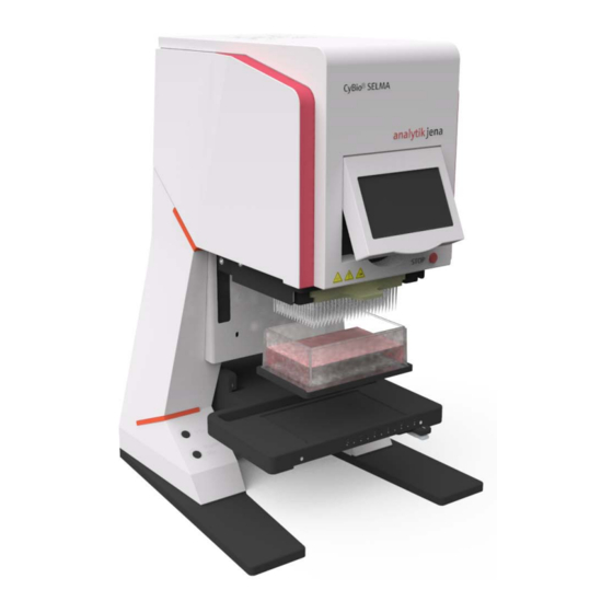
Technical Description Technical Description General System Overview ® The CyBio SELMA is a robot for quick, precise and reproducible processing of 96-well or 384-well microplates in semiautomatic pipetting mode. Applications like replicating or reformatting of microplates or fabrication of dilution series can be performed using 96-channel or 384-channel pistons and the time-proven tip sealing principle. The sys- tem delivers faultless reproducible results. Tip replacement (change) is made easier by ® ® ready-for-use CyBio TipTrays. Because the CyBio SELMA includes a memory function for pipetting cycles, several microplates can be processed in little time. Control action is triggered at the touchscreen display that can be tilted up. This makes it possible to work in sitting and in standing position. Two push-buttons are provided in the support base to facilitate selection of "Pipetting" ("Pip" button) or "Pipetting with prior saved val- ues" ("Move+Pip" button) mode. A work procedure running in semiautomatic mode can be interrupted by actuation of the "STOP" button. Light elements indicate power- on state (if activated). Fig. General system view Light element Tiltable touch screen Guide groove I + II "STOP" button "pip" button for pipetting Pipetting head ® "move + pip" button for CyBio TipTray motion to position and Tray with working positions 1+2 pipetting Knob (adjustable dial) -
Page 26: Operation Controls
Technical Description uct versions, microplates with 384 wells can be positioned in XY-direction on a tray ( chapter 4.1.2) with the help of an adapter for processing in four steps. 4.1.1 Operation Controls ® The CyBio SELMA is provided with operation controls as follows: Power On/Off switch (on rear side) Touch screen ( item 5; Fig. 3) Push-button for triggering a pipetting process Push-button to trigger motion to a prior saved height level with subsequent pipetting process ( item 3; Fig. 3) "STOP" button ( item 6; Fig. 3) Adjustable dial knob ( item 10; Fig. 3) Power On/Off switch and stand by The system includes a power On/Off switch on its rear side. It is also possible to activate stand-by mode in system settings. In this case, the system will change to idle state after ... - Page 27 Technical Description "pip" push-button Triggering piston motion within the pipetting head is a control step in pipetting mode. To trigger this type of piston motion, the "pip" button in the system's support base must be actuated. Piston motion will occur as required for your prior value entries and the following steps will be executed: Aspiration of liquid Dispensing of liquid Motion of pistons into zero-position The pipetting head itself remains stationary, only the pistons do move. "move + pip" button ® In many cases, pipetting jobs have to be performed repeatedly. Accordingly, the CyBio SELMA includes a "move+pip" button that allows you to trigger the next pipetting pro- cess, depending on the current status. In contrast to motion triggered via the "pip" button, this will also cause vertical motion of the pipetting head. The target position of motion triggered in this case follows from the most recently completed pipetting cycle that had been saved. On completion of pipetting, the pipetting head restores its initial position. The order of working steps is as follows: Motion to height level for pipetting Pipetting Motion to pre-pipetting height level STOP button This push-button ( see fig. 2) can be used to interrupt a running pipetting process. All types of motion, i.e. piston motion and motion of the pipetting head, will halt. The pi- petting head will stop immediately. Once a pipetting process has been interrupted, it may be resumed or cancelled using the appropriate display control tools.
-
Page 28: Tray
Technical Description Fig. Knob for motion of the pipetting head "Down" direction of pipetting head motion "Up" direction of pipetting head motion 4.1.2 Tray The tray has two working positions. Working position 1 is fixed. Working position 2 can be shifted to the left column-by-column in a grid-like pattern, so selected individual columns of a given microplate can easily be processed separately. Furthermore, the tray can be installed in two different guide groove positions (I or II; Fig. 7) at the system. This makes it possible to transfer liquid from reservoirs into deep-well microplates using deep-well pipetting tips in a convenient manner. Fig. Tray in working positions 1 and 2 Working position 1 (fixed) Working position 2 (shiftable in column-steps) Spring lever for selection of individual columns Column scale Fig. Guide grooves I and II ®... -
Page 29: External Power Pack
Technical Description 4.1.3 External Power Pack The power pack is intended for wide-range operation. For voltage supply, a line power socket of 100 – 240 VAC (±10 %; 1.7 A max.) and a frequency of 50/60 Hz is required. On its secondary side, the power pack outputs voltage of +24 VDC (2.5 A max.). Fig. External power pack 4.1.4 Terminals & Nameplate Located on the back of the system are the following terminals: Fig. Terminals & nameplate RS 232 service interface (Sub D9-pole jack) 24V DC input On/Off switch (O/I) Nameplate ® CyBio SELMA 2016... -
Page 30: Cover Caps & Connectors
Technical Description 4.1.5 Cover Caps & Connectors Fig. 10: Cover caps (or connectors) – marked Fixed at the rear panel are two cover caps or one cover cap and one connector, de- pending on the product version Fig. 10. Never remove these parts. 4.1.6 External Display Plug cable connector of external display* into the designated terminal at the rearside panel of the system. Remember to turn system power off at first. Once the display is connected, system power supply can be restored. The external display provides identical menus and functions. For disconnection of the external display, system power must be turned off again. ® 2016 CyBio SELMA... -
Page 31: Operating Modes
Technical Description Operating Modes ® The CyBio SELMA is designed for operation control in sitting and in standing operator position. 4.2.1 Operation in Sitting Position Control action is mainly triggered at the control elements that are located on the sup- port base. These include: Knob for motion of the pipetting head Push-button for triggering a pipetting process ("pip") Push-button for triggering motion to the most recent pipetting height with sub- sequent start of pipetting process ("move + pip") Selection of the various desired pipetting modes can equally be achieved via the touch screen on the system's front side. It can be tilted in vertical direction to allow work in sitting and standing position. 4.2.2 Operation in Standing Position System control action in standing operator position is primarily triggered at the touch screen. A pipetting procedure is triggered at the touch screen. This will make the ap- propriate control buttons operational. To vary the height level of the pipetting head, an adjustable dial is provided on the right-hand side of the system. Product Versions NOTE The particular product type (number of pipetting tips and volumes; e. g. 96/250 μl) is indicated on the front of the pipetting head. Product version Number of Maximal vol-... -
Page 32: Function
Technical Description Function ® The CyBio SELMA is a simultaneously working 96-well (384-well) pipetting robot to process microplates (SBS standard) in semiautomated mode. The system's basic functions are: Basic function Explanation – Aspiration of a defined volume Priming – Rinsing of pipetting tips through repeated dispensing and aspiration of a volume (source plate = destination plate) – Dispensing of defined volume with residual ejection – Aspiration of a defined volume Pipetting – Dispensing of defined volume with blowout – Mixing cycles can be performed optionally – Aspiration of a total volume obtained as the sum of pre- Dispensing defined subvolumes – Dispensing of predefined subvolumes in a corresponding number of steps – Aspiration of a predefined volume (sample) Diluting – Aspiration of an air bubble. – Aspiration of a second predefined volume in accordance with a required dilution ratio (diluent) –... -
Page 33: Transportation & Storage
Transportation & Storage Transportation & Storage Transportation CAUTION There is danger to the people's health from contamination of the system! Clean and decontaminate the system before storage or shipment. Fill in and enclose the “Declaration of Safeness” with the system. NOTICE Environmental influences, mechanical shocks or formation of condensed water may destroy individual system components! Take adequate precautions to protect the system from environmental influences, mechan- ical impacts and formation of condensed water during transportation! Temporary open- air storage of the system is prohibited! NOTICE Inexpert packaging is likely to cause damage to the system! Use only original packing for transportation and shipment of the system and its accesso- ries. NOTICE There is danger of material damage. Direct contact of the tip magazine and the pistons may damage the pistons. Never install a tip magazine without pipette tips for transportation of the system! This will void your warranty claims. To prepare the system for transportation, proceed as follows: 1. Install a tip magazine if necessary. 2. Shut the system down ( refer to chapter 10). 3. Use only original packing for transportation. Contact your competent service partner for packing material if necessary. 4. Insert tray in guide groove "II". 5. Install shipping retainer (marked red) above the tip magazine handle. 6. - Page 34 Transportation & Storage 7. To raise the system, hold it by the back of the pipetting head, then place it into the shape-matched lower PE support pad. CAUTION There is danger of physical injury as the system is raised! Do not place your fingers below the tip magazine! Always hold the system by the back of the pipetting head to lift it up. 8. Mount shape-matched upper PE pad onto the system. 9. Pull plastic cover over the system. Make sure that the touch screen is tilted in. 10. Place system into packing case. 11. Put power pack, User Manual and any further accessory item into the additional package unit and place additional package into the packing case. 12. Close packing case and firmly seal it with tape. The system is completely packed for transportation. ® 2016 CyBio SELMA...
-
Page 35: Storage
Transportation & Storage Storage ® If the CyBio SELMA is not installed immediately after arrival of product shipment or is not required for a longer period of time, it should preferentially be stored in its original packing case. Climatic requirements on facilities for system storage are as follows: Temperature range -10 °C to +50 °C 85 % at 30 °C, no formation of condensate Allowable relative air humidity ® CyBio SELMA 2016... - Page 36 Transportation & Storage ® 2016 CyBio SELMA...
-
Page 37: Initial Start-Up & Routine Start-Up Procedure
Initial Start-Up & Routine Start-Up Procedure Initial Start-Up & Routine Start-Up Proce- dure Site Requirements 6.1.1 Installation Requirements ® The room which is selected for CyBio SELMA installation must meet the following en- vironmental requirements: Temperature range +15 °C to +37 °C 85 % at 30 °C, no formation of condensate Allowable relative humidity The atmosphere inside the installation room should be dust-free to a maximum possible degree, free from drafts and from etching vapors. The following rules should be observed for selection of the system site: The installation room must have a stable, horizontal, dry and vibration-free floor. The laboratory table must be designed to carry the weight of the system. Please comply with weight specifications in chapter 2. Do not install the system in the direct vicinity of doors or windows or close to sources of electromagnetic interference. Prevent direct exposure of the system to sun light and radition by heating equip- ment. Provide adequate air conditioning for the room if necessary. -
Page 38: Starting Up
Initial Start-Up & Routine Start-Up Procedure Starting Up 1. Unpacking the system CAUTION Danger of physical injury/material damage! Be aware of the system's weight. Hold the system properly as you retrieve it from the packing case! Do not place your fingers below the pipetting head or the tray. a) Take power pack and accessory units out of the outer shipping case. b) Remove upper part from outer shipping case. Lift system out of its packing case from the top. Hold it firmly by the back of the pipetting head as you do this. Fig. 11: Note regarding removal of the system from its packing d) Check for completeness and intactness of shipment against packing list NOTE Store original packing for case of necessary service! 2. Installing the system a) Place the system on a suitable floor base ( refer to page 7) b) Remove protective plastic cover Remove shipping retainers (store packing parts and shipping retainers) ®... - Page 39 Initial Start-Up & Routine Start-Up Procedure 3. Acclimatizing the System (in power-off state) NOTE The system must undergo acclimatization in order to allow thermal adjustment to the room temperature in the working environment (laboratory). In order to ensure uniform heating (as required), the system should initially remain in power-off state (to exclude ad- ditional internal sources of heat). Complete adaptation to the laboratory’s operating en- vironment is accomplished during a subsequent acclimatization procedure with the system in power-on condition. a) Allow the system to acclimatize for 24 hours or more (in power-off state). 4. Connect power pack NOTICE Make sure that specified voltage is applied to the power socket. a) Connect power pack cable to the dedicated jack on the rearside of the sys- tem ( item 1; Fig. 12) and screw mains plug firmly on. b) Connect power pack to a line power socket with PE conductor 5. Turn system power on a) Use switch on the rearside panel for turning on ( item 2; Fig. 12) Fig.
- Page 40 Initial Start-Up & Routine Start-Up Procedure 6. Initialization a) Initialization starts b) Then follow touch screen instructions Initialization Push “Start” button Start Fig. 13: Initialization - vertical drive Initialization - Blowout » place reservoir » regulate dispensing height » push “Continue” button Continue Fig. 14: Initialization - dispensing of residual volume Initialization - Blowout »...
- Page 41 Initial Start-Up & Routine Start-Up Procedure -0.0mm Menu Priming Pipetting Repeat Sample Dispensing Dilution Reverse Serial Pipetting Dilution Device Change Settings Tips Fig. 16: Main menu 7. Acclimatize system (in power-on state) a) Let the system run in idle mode for 1 hour or more with power on. 8. Pipetting head motion a) Turn rotating knob “Knob (adjustable dial)” on page 17 to achieve motion of the pipetting head into lower limit position.
-
Page 42: Function Testing
Initial Start-Up & Routine Start-Up Procedure Function Testing NOTE Specified function tests must also be performed as part of system routine start-up proce- dures following major down-times and after relocation of the system to another site. 6.3.1 Precision Test Testing for variation coefficient CV (per-centage standard deviation) is performed using a 96-well microplate (384-well microplate) with transparent flat bottom filled with a dye solution. A suitable vertical photometer is used for measurement. The photometer's own precision must be verified and documented according to manufacturer instruc- tions prior to measurement. Materials/Preparation: 1. Prepare 96-well transparent flat-bottom microplate with initial fill of 150 μl 0.1 N NaOH (for 384-well microplate initial fill of 50 μl 0.1 N NaOH): NOTE The result of measurement is adversely influenced by a certain inhomogeneous evapora- tion over the microplate. For this reason, the microplates should be taped immediately after initial placement of di- luens and pipetting of the test volume, and during the shake process. Do not use washed microplates. This may cause excessively great variation in measured values. 2. Always use new pipetting tips for precision measurement. Ensure that the pipet- ting tips and the system are properly wetted (prewetted) before actual measure- ment. To achieve this, let the actual "Reverse pipetting" precision routine run two times ahead of measurement. The dispensing and the residual volume will flow back into the storage reservoir in this case: 3. Testing is performed with an aspiration volume and test volume as specified for the given system type (refer to table below). 4. Dispense the test volume into a microplate with pre-placed NaOH solution (refer to table above). Make sure that the pipetting tips submerge into the pre-placed ... - Page 43 Initial Start-Up & Routine Start-Up Procedure Piston Aspiration Prefill- Standard p-nitro- speed volume volume test phenol dye volume solution 198 μl 2 μl 12 mM ® CyBio SELMA 4 μl/Sek. 10 μl 96/25 μl 190 μl 10 μl 2,4 mM 197 μl 3 μl 12 mM ®...
- Page 44 Initial Start-Up & Routine Start-Up Procedure 5. Tape the microplates after pipetting of the test volume and before shaking. 6. Mix the substances in an orbital shaker (refer to table below). 96-well microplate 384-well microplate Orbital shaker of Shake for 15 min 700 r.p.m. 30 min pause — Shake for 15 min Centrifuge of 2 min centrifuge 2000 r.p.m. 15 min pause 2 min centrifuge Shake for 15 min Orbital shaker — 45 min pause 1100 r.p.m. Shake for 15 min 1 Alternative (Orbital shaker) 7.
-
Page 45: Accuracy Test
Initial Start-Up & Routine Start-Up Procedure 6.3.2 Accuracy Test Accuracy testing determines the level of agreement between a measured dispensed vol- ume (mean value of all readings from a given 96-well microplate) with a predefined (target) volume. Materials/Preparation: Laboratory balance with 1mg minimum resolution. The selected laboratory balance must be subject to regular calibration (check for calibration mark). Lidded 96-well microplate with flat bottom. NOTE Since new microplates, typically, are vacuum-packed, a selected microplate must be un- packed at least one week before testing (the weight of a new microplate may decrease or increase as a result of evaporation and absorption respectively). Accuracy testing is performed with de-ionized water (1bar and 998 mg/cm Test sequence 1. Place a reservoir with de-ionized water in working position 1 of the tray. 2. Prewet pipetting tips following the procedure described in section 6.3.1 („Pre- cision Test”); item 2. 3. Select "Reverse pipetting" mode to perform accuracy testing. 4. Weigh the microplate in empty and in lidded state. 5. Remove lid from the microplate and place microplate in working position 2 of the tray. -
Page 46: Leak Test
Initial Start-Up & Routine Start-Up Procedure 6.3.3 Leak Test Leak testing is required, in order to make sure that the pipetting head is free from points of leakage. Subject to testing are the pistons, the pipetting tips and the silicon membrane. Leak testing consists of aspiration of a defined volume of dye solution into the pipette tips and visually tracking the level of liquid over a time of 30 minutes. Test sequence 1. Make sure the system is in a horizontal position. Carefully place a spirit level onto the tray for this purpose. Adjust horizontal system position if necessary. 2. Remove old pipetting tips. 3. Thoroughly inspect silicon membrane for cracks or sedimentation. Use a suitable light source for this purpose. Carefully clean the silicon membrane using a dust- free, slightly moistened piece of cloth. Exert only moderate pressure, in order to prevent unwanted shifting of the membrane. Use caution to prevent sedimenta- tion remaining in the membrane openings as you wipe the membrane clean. Allow the membrane to dry. 4. Install tip magazine with new tips and tighten tips. 5. Place reagent reservoir onto the tray below the pipetting tips. 6. Move pipetting tips into position close to the reservoir. To do this, press "pip" button at the system and slowly turn the knob (adjustable dial) clockwise. The pipette tips should dip into the solution by at least 2 mm below surface level. 7. Perform prewetting of the pipetting tips similar to the procedure described in sec- tion “Precision Test”. 8. Aspirate 50 % (of end volume) of dye solution. NOTE Keep the pipetting tips submerged during leak testing, in order to prevent formation of droplets at their ends, because droplets may falsify the result of testing. 9. -
Page 47: Operation
Operation Operation CAUTION Beware of potential squeezing or pinching effects! System control action may only be triggered by a single person at a time. Do not place your hands or fingers into the range of pipetting head motion while an automated se- quence is going on. NOTE Where possible given the height of pipetting tips and pipetting vessels, the tray should be pushed into guide groove I in order to keep the motion length of the pipetting head as small as possible. NOTE Use the maximum blowout volume if possible (preset). There are two options for performing the various steps of liquid handling: In manual operation mode, the height for aspiration and dispensing can be set with the help of the knob at the system support base. In partly automated operation mode, the pipetting heights will be automatically restored by motion in accordance with prior saved height settings. NOTICE There is danger of material damage. Make sure that there are no bubbles of residual air in order to avoid excessively high fill levels of the tips as you work in manual or partly automated mode. There is danger of pis- tons coming into contact with liquid and suffering contamination as a result. This kind of danger mainly exists when liquid is drawn from reservoirs of poor filling level or when pi- petting tips submerge to less than the specified depth. Make sure that pistons cannot come into contact with liquid during motion into zero-po- sition. Repeated operation faults may lead to excessively high fill levels and a situation of the kind as described above. Operation Controls ® The CyBio SELMA is provided with operation controls as follows: On/off switch Touch screen ... -
Page 48: Entering Parameters At The Touch Screen
Operation NOTE For a detailed description of control elements, you are referred to chapter 4.1.1. Entering Parameters at the Touch Screen When parameters need to be typed in at the touch screen, the general input window will show. The input window ( see fig. 17) displays a field of control buttons that al- low you to make required parameter entries. Depending on the particular required pa- rameter input (alpha-numerical or purely numerical), numbers, letters and special characters can now be typed in via these buttons. The minimum available parameter settings are displayed at the left and the maximum available setting at the right end of the input line. 0.0 mm Parameter 2 abc 3 def 4 ghi 5 jkl 6 mno 7 pqrs 9 wxyz 8 tuv . */+- Clear Apply Cancel... -
Page 49: Touch Screen - Main Menu
Operation Button "Aa" can be used to switch between capital and small let- tering. This control button will only show when alpha-numerical inputs are permitted. The currently selected mode is displayed above the input field. Supported modes are: 1. Automatic "Aa" (Abc) Each character after space is capitalized, all other charac- ters are in small lettering. 2. Small "a" (abc) Each character is written in small letters. 3. Capital "A" (ABC) Each character is written in capital letters. After pressing of the "Apply" button, the new input value will be checked for correctness. If an input value is found to lie within the permissible limits, but beyond the specified volume range ( refer to page 5), the screen will output one of these two messages: Apply Value too large Value too small Error messages are displayed at the input field. On pressing of "Cancel" the previous entry will be restored. Cancel Touch Screen – Main Menu NOTE The values which are quoted in the following explanatory sections are identical with thos of the pipetting head 96/250 μl. For the values of other pipetting heads, you referred to the parameter table at the end of each chapter. -
Page 50: Priming
Operation -0.0mm Menu Priming Pipetting Repeat Sample Dispensing Dilution Reverse Serial Pipetting Dilution Change Device Settings Tips Fig. 18: Main menu The control buttons for basic pipetting modes are: Priming Pipetting Dispensing Diluting Reverse pipetting Serial dilution The control buttons with extended functionality are: System (system settings) Tip Change NOTE For detailed explanation of pipetting modes, you are referred to chapter “Function”... - Page 51 Operation Touch screen display Explanation 2. Working in Priming menu, make settings for Options ( item 3), Volume and Priming -0.0 mm Abbruch Speed( item 5). Options Speed Current parameter settings will be dis- Priming 5x 120.0 µl/s played below the corresponding button. Volume Load Save Immediately on actuation of the "Volume" 250.0 µl button, the special input window will Change Optionen Optionen Start show. Menu tips Note: If no changes are made in settings, ...
- Page 52 Operation Touch screen display Explanation 7. Use "Start" to trigger a priming pro- cess. Follow instructions on the touch screen. Priming -0.0 mm Abbruch a) Place source plate/destination Options Speed plate onto the tray Priming 5x 120.0 µl/s b) Set height level of pipetting Volume head required for aspiration Load Save 250.0 µl Press button "Pipetting" at the Change Start Optionen Optionen touch screen or push-button Menu tips "pip" on the left-hand side of the support base Partly automated sequence: Press button "Motion & Pipetting" or use "move+pip" push-button on the left-hand ...
-
Page 53: Pipetting
Operation 7.3.2 Pipetting CAUTION There is danger of personal injury or material damage from toxic chemical substances! Put on your personal protection equipment when working with substances of this kind. Consult relevant safety data sheets, manufacturer instructions regarding practical use and national standards for working with substances of this type. Observe the rules and policies for cleaning and contamination. ’Pipetting’ means that a defined volume is exactly aspirated and dispensed again via blowout. Mixed cycles can be performed. Touch screen display Explanation -0.0mm Menu Priming Pipetting 1. Press "Pipetting" in main menu. Sample Repeat Dispensing Dilution Reverse Serial Pipetting Dilution Device Change Settings Tips 2. Once in pipetting menu, define ... - Page 54 Operation Touch screen display Explanation 3. Working in the Pipetting options Pipetting Options 0.0 mm submenu you can define: Abbruch Mixing cycles, Mixing Mixing cycles volume Blowout and 50.0 µl Blowout Mixing volume 70.0 µl (refer to Table 4 on page 46). On actuation of any of these three but- Optionen Optionen Default Apply Cancel tons, the corresponding input win- dow will appear.
- Page 55 Operation Touch screen display Explanation 7. Select "Start" to trigger a pipetting sequence. Follow instructions on the touch screen. a) Place source plate onto the tray b) Set height level of pipetting head required for aspiration Pipetting -0.0 mm Abbruch Press button "Pipetting" at the Options Speed touch screen or push-button 3 x 50 µl "pip" on the left-hand side of 120.0 µl/s Volume the support base Save Load 250.0 µl d) Move pipetting head up e) Place target plate onto the tray Change Optionen Optionen Start...
-
Page 56: Dispensing
Operation ® ® CyBio SELMA CyBio SELMA ® ® 96/25 96/60 CyBio SELMA CyBio SELMA ® ® 96/250 96/1000 CyBio SELMA CyBio SELMA 384/25 384/60 Value Default Value Default Value Default Value Default range range range range Speed (μl/ 2 – 1.0 – ... - Page 57 Operation Touch screen display Explanation -0.0mm Menu Priming Pipetting 1. Press "Dispensing" in main menu. Sample Repeat Dispensing Dilution Reverse Serial Pipetting Dilution Device Change Settings Tips 2. Once in menu Dispensing, define parameter settings for Options ( item 3), Dispensing volume, Dispensing steps and Repeat Dispensing 0.0 mm Speed( item 5) Abbruch Dispensing volume...
- Page 58 Operation Touch screen display Explanation 5. Set the speed at which liquid is to be drawn in and dispensed again in Pipetting Speed 0.0 mm menu Speed Abbruch High 6. Use "Apply" to acknowledge a new setting: Medium Low 40 μl/s 120.0 µl/s Medium 120 μl/s Setting High Optionen Optionen 180 μl/s Apply Cancel Fine tuning: 2.0 – 200.0 μl/s NOTICE There is danger of material damage.
- Page 59 Operation Touch screen display Explanation Repeat Dispensing - Blowout Dispense 25.0 µl, Steps 5, Speed 120.0 µl/s, Blowout 70.0 µl, » place reservoir 8. Place reservoir onto the tray for dis- » regulate dispensing height » push ”Pipetting” button pensing of residual volume if dispensing height already stored push “Move and Pipetting” button 9.
- Page 60 Operation Inter-parametric relations ® CyBio SELMA 96/25 Restriction: Number of dispensing steps * dispensing volume 24 μl Automatic calculation of Aspiration volume = aspiration volume Number of dispensing steps * dispensing volume + 1 μl ® CyBio SELMA 96/60 Restriction: Number of dispensing steps * dispensing volume 58 μl Automatic calculation of Aspiration volume = aspiration volume Number of dispensing steps * dispensing volume + 2 μl ® CyBio SELMA 96/250 Restriction: Number of dispensing steps * dispensing volume 240 μl Automatic calculation of Aspiration volume = aspiration volume Number of dispensing steps * dispensing volume + 10 μl ®...
-
Page 61: Diluting
Operation 7.3.4 Diluting CAUTION There is danger of physical injury or material damage by toxic chemical and biological sub- stances! Put on your personal protection equipment when working with substances of this kind. Consult relevant safety data sheets, manufacturer instructions regarding practical use and national standards for working with substances of this type. Observe the rules and policies for cleaning and contamination. In a ’Diluting’ cycle, a predefined sample volume, an air bubble and a diluent volume are successively taken in according to the desired dilution ratio. Subject to dispensing is the total tip contents via blowout. Touch screen display Explanation -0.0mm Menu Priming Pipetting 1. Press "Diluting" in main menu. Repeat Sample Dispensing Dilution Reverse Serial Pipetting Dilution Device Change Settings Tips 2. - Page 62 Operation Touch screen display Explanation 3. Working in menu Diluting Options Sample Dilution Options 0.0 mm define settings for Abbruch Mixing cycles, Mixing Mixing cycles volume Blowout and 50.0 µl Blowout Mixing volume 70.0 µl (refer to Table 6 on page 54). On selection of any of these buttons, the Optionen Optionen Default Apply Cancel related special input window will be ...
- Page 63 Operation Touch screen display Explanation 7. Select "Start" to trigger a pipetting sequence. Follow instructions on the touch screen. a) Place source plate onto the tray b) Set height level of pipetting head required for aspiration Press button "Pipetting" at the touch screen or push-button "pip" on the left-hand side of the support base d) Move pipetting head up until tips have emerged from liquid e) Press "Pipetting" at the touch Sample Dilution 0.0 mm screen or "Pip" push-button on Abbruch Sample volume the left-hand side of the support Options Speed 20.0 µl base to take in an air bubble Mix. 3 x 50 µl 120.0 µl/s Diluent Place diluent plate onto the tray...
- Page 64 Operation Parameters ® ® CyBio SELMA CyBio SELMA ® ® 96/25 96/60 CyBio SELMA CyBio SELMA ® ® 96/250 96/1000 CyBio SELMA CyBio SELMA 384/25 384/60 Value Default Value Default Value Default Value Default range range range range Sample 0.01 – 0.1 – ...
-
Page 65: Reverse Pipetting
Operation 7.3.5 Reverse Pipetting CAUTION There is danger of physical injury or material damage by toxic chemical and biological sub- stances! Put on your personal protection equipment when working with substances of this kind. Consult relevant safety data sheets, manufacturer instructions regarding practical use and national standards for working with substances of this type. Observe the rules and policies for cleaning and contamination. In a ’Reverse Pipetting’ cycle, a defined volume plus an additional volume are drawn in via overstroke and a volume is subsequently dispensed exactly as defined. This se- quence may also be performed repeatedly. Some residual volume remains in the tip to be dispensed into a reservoir at the end of the process. Reverse pipetting is mainly in- tended for minor volumes and foaming or viscous liquids. Touch screen display Explanation -0.0mm Menu Priming Pipetting 1. Press "Reverse Pipetting" in main Repeat Sample Dilution Dispensing menu. Reverse Serial Pipetting Dilution Device Change Settings Tips... - Page 66 Operation Touch screen display Explanation 3. Once in menu Reverse pipetting Optionen Reverses Pipettieren 0.0 mm options you can define settings for: Blowout and Steps Blowout Steps 70.0 µl (refer to Table 7 on page 58). On selection of any of these buttons, the Default Apply Cancel related special input window will be displayed. 0.0 mm Parameter 4. Press "Apply" to acknowledge a new setting. Note: If no changes are made in settings, ...
- Page 67 Operation Touch screen display Explanation 7. Select "Start" to trigger a pipetting sequence. Follow instructions on the touch screen. a) Place source plate onto the tray b) Set height level of pipetting head required for aspiration Press button "Pipetting" at the touch screen or push-button "pip" on the left-hand side of the support base d) Move pipetting head up e) Place destination plate onto the tray Reverse Pipetting 0.0 mm Set height level of pipetting head Abbruch Aspirate volume required for dispensing Options Speed 250.0 µl 1 Schritt 120.0 µl/s g) Press button "Pipetting" at the ...
- Page 68 Operation Touch screen display Explanation Reverse Pipetting - Piston to zero Asp. 250.0 µl, Disp. 240.0 µl, Count 1, Speed 120 µl/s, Blowout 70.0 µl 8. Move pipetting tips out of liquid » move pipet tips out of the liquid when prompted to do so. » push “Pipetting” button 9.
-
Page 69: Serial Dilution
Operation 7.3.6 Serial Dilution CAUTION There is danger of physical injury or material damage by toxic chemical and biological sub- stances! Put on your personal protection equipment when working with substances of this kind. Consult relevant safety data sheets, manufacturer instructions regarding practical use and national standards for working with substances of this type. Observe the rules and policies for cleaning and contamination. In a ’Serial Dilution’ cycle, a defined volume is taken in column-by- column and a certain pre-filled volume is dispensed again column-by-column. The two portions of liquid are subsequently mixed with each other. Preparation: These pipetting sequences which are defined via menu ’Serial Dilution’ use a tip maga- zine that contains only eight tips in one column Replace tip magazine as described in section 7.4.1. Sequence of actions: Touch screen display Explanation -0.0mm Menu Priming Pipetting 1. Press "Serial Dilution" in main Repeat Sample Dispensing menu. Dilution Reverse Serial... - Page 70 Operation Touch screen display Explanation 2. Working in menu Serial Dilution you can define settings for: Options ( item 3), Transfer volume, Dilution steps and Serial Dilution 0.0 mm Speed( item 5) Abbruch Transfer volume Options Speed (refer to Table 8 on page 62). 250.0 µl 3 x 50 µl 120.0 µl/s Current parameter settings will be ...
- Page 71 Operation Touch screen display Explanation NOTICE There is danger of material damage. To be able to aspirate or dispense liquid on stage 1 of the tray, stage 2 must be pushed into the leftmost position. This is necessary to allow unobstructed motion of the pipet ting head 7. Select "Start" to trigger a pipetting sequence. Follow instructions on the touch screen. a) Place source plate onto the tray b) Bring column selected for aspi- ration of liquid into position under the pipetting tips if nec- essary (use spring lever to shift the table as appropriate) Set height level of pipetting head required for aspiration d) Press button "Pipetting" at the touch screen or push-button "pip" on the left-hand side of the support base Serial Dilution 0.0 mm e) Move pipetting head up Abbruch Transfer volume Place target plate onto the tray Options Speed 250.0 µl and bring column to be filled ...
- Page 72 Operation Touch screen display Explanation Partly automated sequence: Press button "Motion & Pipetting" or "move + pip" at the support base (instead of but- ton "Pipetting) for action item 7d. A previously completed sequence of manual liquid handling steps will be saved for subsequent reuse with current parameter settings in au- tomatic mode. Serial Dilution - Piston to zero Dil. 5x, Vol. 250.0 µl, Mix. 50.0 µl (3x), Speed 120.0 µl/s 8. Move pipetting tips out of liquid » move pipet tips out of the liquid when prompted to do so. ...
-
Page 73: Extended Functions
Operation Extended Functions 7.4.1 Tip Change CAUTION ® Beware of crushing/pinching hazard as the CyBio TipTray is being fixed! Do not place your hands or fingers into the motion range of tip mounting and fixing or that of the pipetting head. ® To replace a CyBio TipTray, proceed as follows: -0.0mm Menu 1. Turn knob (adjustable dial) until the Priming Pipetting pipetting head is returned into its zero position. Sample Repeat Dispensing Dilution 2. Press button "Tip Change" in main Reverse menu. Serial Pipetting Dilution Device Change Settings Tips Change Tips 0.0 mm Abbruch Tips are loosen . -
Page 74: System Settings
Operation 7.4.2 System Settings Basic system settings can be specifically adapted. Basic system settings include: Function Meaning Idle state The time until activation of system idle state; during idle state, the design elements keep blinking Vertical speed Designates the speed of vertical motion of the pipetting head when function "Motion & Pipetting" is active Pause Means a break in operation after aspiration/dispensing Lighting Provides options to vary the illumination level at the sys- tem: Touch screen lighting Work area lighting General lighting (design elements) Language Option to switch to other working language Service For querying the current firmware version Queries statistics – Piston cycles – Total volume – Z-axis cycles – Total Z-axis motion length To make changes in system settings, proceed as follows: -0.0mm Menu Priming Pipetting Press button"System" in main menu. Sample Repeat Dispensing... - Page 75 Operation 0.0 mm Parameter Press "Apply" to acknowledge one or more new settings. 2 abc 3 def Note: On selection of button "Default" all 4 ghi 5 jkl 6 mno system settings will be restored to their 7 pqrs 8 tuv 9 wxyz default values. The working language is . */+- Clear English in this case. Apply Cancel Default To change the selection for language, Set language 0.0 mm press button "Language" in submenu System Settings. English Select desired language in the window ...
- Page 76 Operation Parameters ® CyBio 96-25/60/250/1000 μl SELMA ® CyBio 384-25/60 μl SELMA Name Unit of mea- Value range Default sure Idle State 0 – 180 Pause refer to 1 – 180 Vertical speed mm/s 10 - 80 Lighting – Touch screen 10 — 100 – Work area 0 — 100 – General 0 = Off; >0 = On English Language German...
-
Page 77: Saving & Loading Of Parameter Sets
Operation 7.4.3 Saving & Loading of Parameter Sets Parameter entries can be assigned their own name before they are saved on the system. These parameters can be loaded back from memory. They will be available for reuse at once. Available memory capacity is not below 10 parameter sets for each pipetting mode. Saving parameter sets Touch screen display Explanation Pipetting -0.0 mm Abbruch Options Speed 1. To save a parameter setting you 3 x 50 µl 120.0 µl/s have changed, press "Save" in the Volume corresponding menu. Save Load 250.0 µl Change Optionen Optionen... - Page 78 Operation Loading parameter sets Touch screen display Explanation Pipetting -0.0 mm Abbruch Options Speed 3 x 50 µl 120.0 µl/s 1. To load parameters, press "Load" in Volume the corresponding menu. Load Save 250.0 µl Change Optionen Optionen Start Menu tips Pipetting - Load 0.0 mm 2. Use arrow keys to select a desired parameter set Test Pipetting volume:...
-
Page 79: Idle State
Operation Idle State The system includes a standby function. Working in submenu System Settings ( see section 7.4.2), you can use button "Idle State" to set a time between 1 min and 180 min (default setting is 30 min). With operation control in the main menu, the sys- tem will default to the standby function if not served on expiry of the time setting for idle state. Shortly before idle state turns active, the pipetting head will automatically re- turn to its zero position (upper mechanical stop). Lighting and the drives will turn off and the design elements blink. To make the system operational again, it is enough to touch the touch screen anywhere within its boundaries. NOTE If a time setting of 0 min has been stored, the standby function will be inactive. NOTE If there is liquid in the pipetting tips, i.e. a pipetting routine is currently running, the system will not default to idle state. ® CyBio SELMA 2016... -
Page 80: Specific System Features (Pipetting Head)
Operation Specific System Features (Pipetting Head) Aspiration and dispensing of liquid is accomplished by piston motion. The piston sus- pension point has a mechanical freeplay (slackness). This means: After each reversal in piston motion direction, the piston drive initially covers a certain travel length without actually moving the pistons, and, hence, without aspirating or dispensing any liquid. This motion length corresponds to the amount of freeplay. In order to prevent dosing errors, a volume cycle is organized in such a way that the pis- ton reversal point lies outside of the actual pipetting range (motion into zero-position, aspiration with additional stroke) or is corrected by suitable compensatory motion (dis- pensing with additional stroke). 7.6.1 Aspiration with additional stroke Fig. 19: Aspiration with additional stroke Zero-position A1 = D2: Nominal pipetting volume Aspirate volume with Additional aspiration volume additional stroke and reverse Dispensed additional volume < A2 piston direction (additional stroke) Upper freeplay Nominal pipetting volume Exactly dispense volume Residual volume (proportional to (single volume or partial freeplay) volumes) Residual dispensing... -
Page 81: Aspiration Without Additional Stroke
Operation Piston motion starts in zero-position (1) and continues beyond the position that corre- sponds to nominal pipetting volume. The pistons are then lowered back into this posi- tion (2). As part of this motion phase, the upper freeplay (3) is overcome. At the time of direction reversal, an additional volume (D1) is dispensed. Due to piston reversal mo- tion, this volume is smaller than the aspirated additional stroke volume (A2). The tip re- tains the nominal pipetting volume (D2) and a certain residual volume (D3). Exact volumes can be dispensed in the next step (4) (in a single step or a multi-step se- quence). After the nominal pipetting volume has been dispensed, the pipetting tip will contain the residual volume (D3) that results from upper direction reversal. This volume is dispensed with additional stroke (5) into a waste box or the reservoir. Since the stroke length is greater than actually required to dispense the residual volume (D3), the residu- al volume will be fully dispensed with air dispensed subsequently (D4). A volume cycle will be complete on "Motion to zero-position". On selection of a "Piston motion" (6) command, the pistons will move up to their initial positions, travelling through the length of lower freeplay as they do so. No liquid must be involved in this process, i.e. the pipetting head with the pipetting tips must have left the zone of liquid. Liquid which is aspirated in the process may result in dosing errors or contamination of pistons. 7.6.2 Aspiration without additional stroke Fig. 20: Aspiration without additional stroke Zero-position A1 = D2: Nominal pipetting volume Aspiration Upper freeplay Dispensing with additional stroke Motion to zero-position ® CyBio SELMA 2016... -
Page 82: Precision Performance (Pipetting Head)
Operation Where liquid is aspirated without additional stroke, it must be dispensed in a single step, in order to achieve precise results. This cycle must provide for a motion length that is greater for dispensing (4) than that for aspiration (2). Since the reversal point of pis- ton motion lies within the motion range that is covered by the pistons for dispensing, no volume is dispensed on excession of the upper freeplay (3). If dispensing motion cov- ers a motion length that is greater than actually required for a given nominal volume, the previously aspirated volume will be completely dispensed from the pipette tip, with subsequent dispensing of air (D2). On selection of a "Piston motion" (5) command, the pistons will move up to their initial positions, travelling through the length of lower freeplay length as they do so. No liquid must be involved in this process, i.e. the pipetting head with the pipetting tips must have left the zone of liquid. Liquid which is aspirated in the process may result in dosing errors or contamination of pistons. Precision Performance (Pipetting Head) ® The CyBio SELMA works based on the principle of air displacement. This means that 96 (384) pistons are mechanically powered by a common drive to perform motion in 96 (384) air spaces which are defined by the pipetting tips and the internal seals. The volume resolution of piston motion corresponds to one tenth or one hundredth of a mi- croliter. The achievable degree of precision is limited and influenced by the: wettability of tips, dimensional stability of their outlet opening, way in which the system and involved liquids are handled. the physical & chemical properties of liquids the quality of microplates You are advised to follow these rules: NOTE Aspiration and dispensing of liquid is accomplished through overpressure and underpres- sure created as a result of piston motion. A work operation of either kind is completed on reaching pressure balance. The time required to reach this state depends - among other ... - Page 83 Operation NOTE By wetting the tip with liquid, you may influence the achievable level of precision and ac- curacy. As a matter of importance, tips should therefore be submerged into the liquid vol- ume just as much as necessary for a particular process. In addition, the depth of immersion should always be the same over several cycles. Make always sure that the reservoir has a sufficient fill level. ® CyBio SELMA 2016...
- Page 84 Operation ® 2016 CyBio SELMA...
-
Page 85: Fault Removal
Fault Removal Fault Removal WARNING Physical contact with voltage-carrying parts may cause bodily injury or even death! Never open the power pack! Refrain from any kind of repair work on the power pack. Contact the Customer Service Department or its authorized service contractor on noticing a faulty condition. Malfunction or faults during operation will be displayed on the working screen. Where operating trouble is obviously due to operator action, work may be resumed after re- moval of the error situation ( see section 8.4). Check all potential fault sources on occurence of a fault. If problems are found to per- sist after this check or on identification of an undescribed fault, you should notify the Customer Service Department of Analytik Jena AG or its authorized service contractor. NOTE Perform decontamination of the system before necessary service work begins. Use “Declaration of Safeness” on page 89 for confirmation of the decontaminated state as a compulsory prerequisite for service. Faulty Value Entries If an input value is found to be out of system specifications, the touch screen will dis- play a corresponding message: 0.0 mm Parameter Value too large 1. Type in a value that is within speci- 3 def 2 abc fications ( refer to chapter 7; ... -
Page 86: Interruption Of Pipetting Routine With Stop But- Ton
Fault Removal Change Tips 0.0 mm Abbruch 1. Push the tip magazine in until Please insert the tiptray and push the button “Continue”. mechanical stop position 2. Press button "Continue" The tip magazine is fixed. Continue Optionen Optionen Interruption of Pipetting Routine with STOP But- On becoming aware of an error in the course of a pipetting routine or noticing foreign unwanted matter below the pipetting tips, you may halt motorized motion by pressing the STOP button. The following windows will show: On pressing of the STOP button: Stop 22.0 mm... -
Page 87: Error Handling
Fault Removal Error Handling 8.4.1 System Malfunction or Failure Situations On becoming aware that the system can not be turned on, you should check for all of the following items: WARNING Physical contact with voltage-carrying parts may cause injury or even death! Let checks of the electrical system only perform by an expert electrician! ® Is power switch on the rearside panel of the CyBio SELMA in On position ( refer to page 29) Is power cable correctly plugged into power pack and line power socket, respec- tively Is operating voltage of the correct level available at the line power socket (check by expert electrician only)! Is (secondary-side) power pack cable correctly plugged and screwed to the ® CyBio SELMA ( refer to page 29). NOTE If the power pack is found to have a defect or if the system still cannot be turned on after all aspects mentioned above have been checked, you should notify the Service Depart- ment or its authorized service contractor. Operate the system only with an original power pack. -
Page 88: Initialization Or Program Sequencing Faults
Fault Removal 8.4.2 Initialization or Program Sequencing Faults If a fault situation occurs during initialization of the system or in the course of a pro- gram sequence, the touch screen displays a corresponding message. The system will reperform the initialization routine in this case. This process will be repeated until the initialization routine runs through without any fault ( chapter 6.2; item 6). If an error occurs during a program sequence, operation will stop. Any residual amounts of liquid must be removed from the pipetting tips in such cases. A "Blowout" is performed for this purpose. Error 22.0 mm Abbruch “Error in setting pipetting speed.” Example of error display. Errorcode: 03 1. Press "Continue". Continue Optionen Optionen Aborted - Blowout 22.0 mm Abbruch » place reservoir »... -
Page 89: Power Failure
Fault Removal Fault Error on piston motion to zero-position. Error on piston reference motion. Unknown error. System error Error on tightening of tips. Error on releasing of tips. Tips not tightened. Sensor error. System operation stopped. Operator break. NOTE Always follow prompts and advice on the touch screen in the event of a fault situation. Power Failure If system power supply is turned off unexpectedly or voltage supply fails because of a defective power pack, the initialization routine will be triggered following repair and restoration of power ( refer to chapter 6.2; item 6). If there had been liquid in the pipetting tips at the moment of power failure, this liquid will be dispensed into a reser- voir as part of initialization. On successful completion of the initialization routine, work may be resumed. ® CyBio SELMA 2016... - Page 90 Fault Removal ® 2016 CyBio SELMA...
-
Page 91: Maintenance & Care
Maintenance & Care Maintenance & Care Safety Notes WARNING Physical contact with voltage-carrying parts may result in death, injury or material dam- age! Never open the power pack! Turn power supply at the main power switch off and disconnect the power pack from the line socket and the system before you begin any kind of work for maintenance or care. NOTICE Penetrating liquid may cause material damage to electrical or electronic components! Make sure that no liquid can penetrate into the inner system space during work for main- tenance or care. You should also follow the specifications on “Chemical Resistance” on page 13. NOTE Intervention into mechanical and electrical parts in the inner system space may not be per- formed by anyone other than Customer Service engineers or specifically authorized expert personnel. To ensure that your system is kept in a state of optimal adjustment and faultless function over a longer period of time, we recommend the conclusion of a service/maintenance contract. Work for maintenance and care must be performed at regular intervals ( see section 9.2.1) as specified and follow any of these rules: Never use cleaning powder, paint thinners or solvents like petrol or acetone to clean system parts. These substances are likely to attack the system surface. Use a soft piece of cloth moderately moistened with a mild soapy or disinfectant solution to clean the system. Spraying cleaner-sprays or similar agents onto the system is dangerous and there- fore not permitted. Spray contains gases that may ignite. NOTE Contamination, for example, dried-in liquid may give rise to increased wear and tear of ... -
Page 92: Maintenance Work
Maintenance & Care Maintenance Work 9.2.1 Overview CAUTION There is danger of physical injury and material damage by chemical or biological sub- stances! Always perform a system decontamination process before proceeding to work for main- tenance or care. Required work items of scheduled maintenance and care are listed in the following ta- ble together with related intervals. Maintenance action Maintenance interval Weekly Monthl Half- yearly Wipe down casing and touch screen Clean tray Clean tray guiding grooves ® Replace used tips in CyBio TipTrays ® Clean CyBio TipTrays, perform autoclaving if necessary ( see section 9.2.2) Inspect sealing plate ( see section 9.2.3) for clean condition Perform precision test ( refer to page 32) Perform leak test ( refer to page 36) Inspect external power pack (cabling, PE-con- ductor check) (only by skilled electrician) -
Page 93: Cybio ® Tiptray
Maintenance & Care ® 9.2.2 CyBio TipTray NOTICE There is danger of material damage. Direct contact between the tip magazine and the pistons may damage the pistons. Never install a tip magazine without pipetting tips in the system! The use a tip magazine with no tips installed will void any warranty claims! NOTE If the system is not required for several hours or days, the tip magazine must remain in the system. During work for maintenance or care, you should also make sure that there are no bub- bles of residual air in the tips, because these will cause excessively high fill levels of the tips. There is danger of pistons coming into contact with liquid and suffering contami- nation as a result. This kind of danger mainly exists where liquid is drawn from reser- voirs with poor filling level or tips are submerged not deep enough. Make sure that pistons cannot come into contact with liquid during motion into zero- position. Repeated faulty operation may lead to excessively high fill levels and a situa- tion of the kind as described above. 9.2.3 Sealing Plate NOTE Where pipette tips are changed more frequently, fine fluff-ball stock or dust may settle on the sealing plate, impairing the efficiency of sealing. You are advised to follow these rules: 1. Do not use dusty pipetting tips. 2. Inspect sealing plate approximately once in a month. 3. Trigger tip change routine ( refer to chapter 7.4.1) and remove the tip maga- zine from the system for inspection and cleaning. The sealing plate can now be accessed from below. Use a non-shedding slightly moistened cloth for cleaning. Alternatively, specific microplate adhesive tape (nunc™ 236269) can be carefully affixed to, and removed from, the sealing plate again. - Page 94 Maintenance & Care ® 2016 CyBio SELMA...
-
Page 95: Shutting Down
Shutting Down Shutting Down CAUTION There is potential danger of personal injury or damage to the system if cables are removed in energized state! Always turn power off before you remove the power supply cable from the power pack! Make sure that the power pack is disconnected from the line power socket before you remove the cable. If the system is not required for operation during a longer period of time, proceed as follows for shutting down: 1. Remove microplates from the tray. 2. Transfer On/Off switch into position "0" 3. Disconnect power cable of external power pack from line power socket. 4. Unfix power supply cable at DC inlet port of the system and remove cable. 5. Clean and disinfect the system in accordance with the rules for the handling of materials and substances that were used most recently ( refer to chapter 9). 6. Install shipping retainer around tip magazine. 7. Protect the system from sedimentation of dust (put on cover of packing foil). Shutting down is now complete. ® CyBio SELMA 2016... - Page 96 Shutting Down ® 2016 CyBio SELMA...
-
Page 97: Accessories & Spare Parts
Accessories & Spare Parts Accessories & Spare Parts 11.1 Accessories NOTE The system, its accessory items and consumable materials have been matched to each oth- er as part of manufacturing. Use only accessories and consumables of the type recom- mended by the Manufacturer. No liability will be accepted on the part of the Manufacturer in the event of damage or malfunction which is found to be due to the use of other accessories or consumables (no- tably, pipetting tips). For more detailed information about available pipetting tips and magazines, you should consult our latest catalog. ® CyBio SELMA 2016... - Page 98 Accessories & Spare Parts ® 2016 CyBio SELMA...
-
Page 99: Waste Disposal
Waste Disposal Waste Disposal CAUTION There is danger of physical injury or material damage by toxic chemicals and biological substances! You are advised to put on personal protection equipment for disposal of consumables, reagents or the system itself. Follow safety data sheets and notes on practical use issued by manufacturers regarding the handling of dangerous chemical and biological substanc- 12.1 Consumables NOTE To dispose consumable materials, proceed in accordance with binding national and inter- national regulations on safety and environmental protection. To store or dispose used pipetting tips, use only lockable containers that are spe- cifically designated for this purpose and are labelled correspondingly. 12.2 Reagents NOTE To dispose reagents, proceed in accordance with binding national (e. g. Hazardous Mate- rials Ordinance) and international regulations on safety and environmental protection (e. g. "Laboratory Safety Manual" of WHO). Take risk category of selected substances into account. Biological samples must be treated in accordance with locally binding regulations for the handling of infectious material. Hazardous substances and related containers must not be disposed as domestic waste or allowed to drain into the sewer or the soil. The appropriate rules and practices must be closely followed for disposal of such. ® CyBio SELMA 2016... -
Page 100: System & Components
Waste Disposal 12.3 System & Components CAUTION There is danger of physical injury or material damage by toxic chemical and biological sub- stances! Decontaminate or disinfect the system before disposal. NOTE Unless otherwise agreed, the system, including its components, must be disposed in ac- cordance with latest provisions of law on termination of its lifetime or when taken out of service. Respective action will be the sole responsibility of the system owner. The statutory bases for disposal are provided by the following EU Directives or their re- spective implementations into national law within the EU: EU Directive 2002/95/EC (RoHS) EU Directive 2002/96/EC (Waste Electrical and Electronic Equipment) ® 2016 CyBio SELMA... - Page 101 Index Index Output voltage . . . . . . . . . . . . . . . .7 Accessories . . . . . . . . . . . . . . . . . . . . 87 Accuracy testing . . . . . . . . . . . . . . . . 35 Fault . . . . . . . . . . . . . . . . . . . . . . . . . .78 Action for removal . . . . . . . . . . . . . . 75 Faulty settings . . . . . . . . . . . . . . . . . .75 Activation . . . . . . . . . . . . . . . . . . . . . 64 Faulty values . . . . . . . . . . . . . . . . . . . .75 Adjustable dial . . . . . . . . . . . . . . . . . 17 Features . . . . . . . . . . . . . . . . . . . . . . .70 Airborne sound emission . . . . . . . . . . 7 Function test . . . . . . . . . . . . . . . . . . .32 Aspiration with additional stroke . . . 70 Function testing . . . . . . . . . . . . . . . . .32 Aspiration without additional stroke . 71 Gas pressure spring . . . . . . . . . . . . . .77 Button "move + pip" . . . . . . . . . . . . 17 Guide grooves . . . . . . . . . . . . . . . . . .18 Care ...
- Page 102 Index move + pip . . . . . . . . . . . . . . . . . . . . 15 Recommissioning . . . . . . . . . . . . . . . .27 Replacement of gas pressure spring . .82 Reverse pipetting . . . . . . . . . . . . .22, 55 Name . . . . . . . . . . . . . . . . . . . . . . . . . 5 Routine start-up . . . . . . . . . . . . . . . . .27 Nameplate . . . . . . . . . . . . . . . . . . . . 19 Notes . . . . . . . . . . . . . . . . . . . . . . . . . 1 Safety labeling . . . . . . . . . . . . . . . . . . .9 Safety notes . . . . . . . . . . . . . . . . . . . .81 On/Off switch . . . . . . . . . . . . . . . . . . 16 Saving . . . . . . . . . . . . . . . . . . . . . . . .67 Operating conditions . . . . . . . . . . . . . 7 Saving of parameter sets . . . . . . . . . .67 Operating data . . . . . . . . . . . . . . . . . . 7 Scope of delivery . . . . . . . . . . . . . . . . .4 Operating modes . . . . . . . . . . . . . . . 21 Sealing plate . . . . . . . . . . . . . . . . . . .83 Operating trouble . . . . . . . . . . . . . . . 77 Serial Dilution Operating voltage . . . . . . . . . . . . . . . . ...
- Page 103 Index Tip change . . . . . . . . . . . . . . . . . 22, 63 Tip fixing . . . . . . . . . . . . . . . . . . . . . 11 Tip magazine . . . . . . . . . . . . . . . . . . 75 Tip mounting . . . . . . . . . . . . . . . . . . 11 Tip replacement . . . . . . . . . . . . . . . . 22 Tip types . . . . . . . . . . . . . . . . . . . . . 5, 6 Touch screen . . . . . . . . . . . . . . . 16, 39 Toxic substances . . . . . . . . . . . . . . . . 13 Transportation . . . . . . . . . . . . . . . 7, 23 Tray . . . . . . . . . . . . . . . . . . . . . . . . . 18 Type . . . . . . . . . . . . . . . . . . . . . . . . . . 5 Vertical speed . . . . . . . . . . . . . . . 64, 66 Volume range . . . . . . . . . . . . . . . . . 5, 6 Volume resolution . . . . . . . . . . . . . . 72 Warning notes . . . . . . . . . . . . . . . 2, 10 Warning signs . . . . . . . . . . . . . . . . ...
- Page 104 Index ® 2016 CyBio SELMA...
Need help?
Do you have a question about the Analytik Jena CyBio SELMA and is the answer not in the manual?
Questions and answers