Table of Contents
Advertisement
Quick Links
Advertisement
Table of Contents

Related Manuals for Endress+Hauser Analytik Jena CyBio FeliX


Summary of Contents for Endress+Hauser Analytik Jena CyBio FeliX
- Page 1 Operating Manual CyBio FeliX...
- Page 3 © Copyright Copyright 2018 Analytik Jena AG All rights reserved. No part of this documentation may be duplicated, photocopied, saved to a storage system or transferred to electronic media without prior written permission of the publisher. Publisher Analytik Jena AG Konrad-Zuse-Strasse 1 07745 Jena Germany Tel: +49 3641 77 70 Fax:+49 3641 77 9279 Service Support Tel: +49 3641 77 9449 E-Mail: service.cybio@analytik-jena.de Ordering code number 30-5015-100-24BLE08 Document type Translation of Original User Manual version Serial number Refer to product nameplate Registered trademarks: ® CyBio ........Analytik Jena AG, Germany Title to all other trademarks or brands which are referenced in this User Manual belongs ...
- Page 5 EG Konformitätserklärung EC Declaration of Conformity Name und Anschrift des Herstellers: Name and address of the manufacturer: Analytik Jena AG Konrad-Zuse-Straße 1 D-07745 Jena Hiermit erklären wir, dass das nachstehend beschriebene Produkt Herewith we declare, that the product described below ®...
- Page 9 Einbauerklärung Declaration of Incorporation Name und Anschrift des Herstellers: Name and address of the manufacturer: Analytik Jena AG Konrad-Zuse-Straße 1 D-07745 Jena Hiermit erklären wir, dass die nachfolgend We declare herewith that the following bezeichnete unvollständige Maschine wegen partly completed machinery as a result ihrer Konzipierung und Bauart sowie in der von uns of design, construction and the version put in in Verkehr gebrachten Ausführung den folgenden...
- Page 10 2018...
-
Page 11: Table Of Contents
Table of contents General Information ........1 General User Manual Advice ... - Page 12 4.1.3 Enclosure with Blind. . . . . . . . . . . . . . . . . . . . . . . . . . . . . . . . . . . . . . . . 27 4.1.4 Decks. . . . . . . . . . . . . . . . . . . . . . . . . . . . . . . . . . . . . . . . . . . . . . . . . . . 28 4.1.5 LED – Operating State Indicator . . . . . . . . . . . . . . . . . . . . . . . . . . . . . . . 31 4.1.6 Head Mount . . . . . . . . . . . . . . . . . . . . . . . . . . . . . . . . . . . . . . . . . . . . . 33 4.1.7 Pipetting Head Versions* . . . . . . . . . . . . . . . . . . . . . . . . . . . . . . . . . . . . 34 4.1.8 Fan . . . . . . . . . . . . . . . . . . . . . . . . . . . . . . . . . . . . . . . . . . . . . . . . . . . . 35 4.1.9 Connector panel . . . . . . . . . . . . . . . . . . . . . . . . . . . . . . . . . . . . . . . . . . 36 Mode of Operation . . . . . . . . . . . . . . . . . . . . . . . . . . . . . . . . . . . . . . . . . . . 38 Operating Modes . . . . . . . . . . . . . . . . . . . . . . . . . . . . . . . . . . . . . . . . . . . . 38 Packaging, Transportation & Storage..... . . 39 Safety Notes . . . . . . . . . . . . . . . . . . . . . . . . . . . . . . . . . . . . . . . . . . . . . . . .
- Page 13 7.6.1 General Commands (Summary Table) . . . . . . . . . . . . . . . . . . . . . . . . . . 56 7.6.2 Removal of Transportation Lock . . . . . . . . . . . . . . . . . . . . . . . . . . . . . . . 58 7.6.3 Preparing for Head Replacement/Turning Off . . . . . . . . . . . . . . . . . . . . . 59 7.6.4 Move in X-, Y- & Z-Direction . . . . . . . . . . . . . . . . . . . . . . . . . . . . . . . . . 60 7.6.5 Load/Unload Tips – Pipetting Head T . . . . . . . . . . . . . . . . . . . . . . . . . . . 62 7.6.6 Tip Mounting/Tip Replacement – Pipetting Head R . . . . . . . . . . . . . . . . . 63 7.6.7 Pipetting . . . . . . . . . . . . . . . . . . . . . . . . . . . . . . . . . . . . . . . . . . . . . . . . 67 Turning Off . . . . . . . . . . . . . . . . . . . . . . . . . . . . . . . . . . . . . . . . . . . . . . . . . 69 “What to do if...“ ........71 Safety Notes . . . . . . . . . . . . . . . . . . . . . . . . . . . . . . . . . . . . . . . . . . . . . . . .
- Page 14 11.5 Further Accessories . . . . . . . . . . . . . . . . . . . . . . . . . . . . . . . . . . . . . . . . . . . 96 11.6 Spare Parts . . . . . . . . . . . . . . . . . . . . . . . . . . . . . . . . . . . . . . . . . . . . . . . . . 96 12 Waste Disposal ......... 97 12.1 Consumables ...
- Page 15 Table of illustrations Fig. Certification sign . . . . . . . . . . . . . . . . . . . . . . . . . . . . . . . . . . . . . . . . . . . . . 12 Fig. Warning signs at the system . . . . . . . . . . . . . . . . . . . . . . . . . . . . . . . . . . . . . 16 Fig. Warning sign at the pipetting head. . . . . . . . . . . . . . . . . . . . . . . . . . . . . . . . 16 Fig. Danger zones . . . . . . . . . . . . . . . . . . . . . . . . . . . . . . . . . . . . . . . . . . . . . . . . 17 Fig. Basic unit . . . . . . . . . . . . . . . . . . . . . . . . . . . . . . . . . . . . . . . . . . . . . . . . . . . 25 Fig. Variant without enclosure/blind . . . . . . . . . . . . . . . . . . . . . . . . . . . . . . . . . . 26 Fig. Nameplate . . . . . . . . . . . . . . . . . . . . . . . . . . . . . . . . . . . . . . . . . . . . . . . . . . 27 Fig. Nameplate . . . . . . . . . . . . . . . . . . . . . . . . . . . . . . . . . . . . . . . . . . . . . . . . . . 27 Fig. Deck positions . . . . . . . . . . . . . . . . . . . . . . . . . . . . . . . . . . . . . . . . . . . . . . . 28 Fig. 10: Heights – Deck A, B and C . . . . . . . . . . . . . . . . . . . . . . . . . . . . . . . . . . . . . . 29 Fig.
- Page 16 Fig. Clean bench and door monitoring set. . . . . . . . . . . . . . . . . . . . . . . . . . . . . 102 Fig. Door monitoring set . . . . . . . . . . . . . . . . . . . . . . . . . . . . . . . . . . . . . . . . . . 103 Fig. Clean bench . . . . . . . . . . . . . . . . . . . . . . . . . . . . . . . . . . . . . . . . . . . . . . . . 104 Fig. Safety light curtain . . . . . . . . . . . . . . . . . . . . . . . . . . . . . . . . . . . . . . . . . . . 104 Fig. Pin assignment for connecting ESTOP IN . . . . . . . . . . . . . . . . . . . . . . . . . . . 107 2018...
-
Page 17: General Information
General Information General Information General User Manual Advice This User Manual informs about the setup and function of the system. It provides qualified operating personnel with the knowledge that is required to handle the system in a safe manner. This Manual further contains instructions and advice about general system care and the Manufacturer’s defined scope of maintenance work items. In addition, you may use this Manual to analyze fault situations for potential causes and take appropriate measures for fault removal. This User Manual must be readily available to operating and maintenance personnel at all times! NOTE The information contained herein reflects the latest state of knowledge at the moment of going to press. Analytik Jena AG reserves the right to make changes if deemed nec- essary in the interest of technical progress. Target Group This User Manual addresses: Qualified and properly trained expert personnel who are able to operate the system and provide general care (→ “Requirements for Operating Personnel” on page 18). Employees with responsibility for: – the planning of process sequences/operating procedures, – preventive maintenance & cleaning work, – safety devices, etc. ®... -
Page 18: Conventions
General Information Conventions 1.3.1 Textual Markups Work instructions involving a timed sequence are numbered and merged to action units to specify related results. Enumeration involving no timed sequence is shown as a bullet-style list, sub-level numbering or as a dash-style list. Safety notes are marked by a pictogram and a signal word (→ “Warning Signs” on page 3). Specific action-related safety notes will precede the actual instruction. Instructions, commands, control buttons, text fields, check boxes and the like are marked as shown for ”Load“ command sample. Optional outfit components or versions are marked with *. For graphic design styles of cross-references, you are referred to the table below: Table 1: Graphic design styles of cross-references Type of cross-reference Graphic style Explanatory note → Fig. -
Page 19: Warning Signs
General Information 1.3.2 Warning Signs WARNING Indicates a potentially hazardous situation. May result in death or serious injury if not avoided. CAUTION Dangerous situation! Potential consequences: light or moderate physical injury. NOTICE Dangerous situation! Potential consequences: material damage. NOTE Useful application advice, no potential danger involved. NOTE Note regarding environmental protection. ® CyBio FeliX 2018... -
Page 20: Intended Purpose
General Information Intended Purpose The system provides a simultaneously working pipettor (model versions or from one to a maximum of 384 channels depending on the type of pipetting head). It is intended for automated processing of microplates. The available range of applications is restricted by the scope of included functional soft- ware and firmware, as well as the scope of delivery. For this reason, the user is prohibited from operating the system in any way other than specified in this User Manual. Conforming Use ® The CyBio FeliX pipettor has been developed to allow the automated processing of microplates in chemical and biological laboratories. In the fields of medicine and diagnostics the system’s intended use is restricted to re- search. Its basic functions are the aspiration and dispensing of liquid from and into a microplate, reservoir, (column single well or tube). The term conforming use also presupposes that: the system is operated by qualified and trained research and laboratory personnel all operating requirements, procedural sequences and related safety notes quoted or described in this User Manual are duly observed all specifications in this Manual regarding system start-up, operation, preventive maintenance and care are met applicable safety standards or rules are always fulfilled. Any use other than or in excess of these rules will be regarded as non-conforming! The user will be solely liable for damage resulting from a case of non-conformance. The definition for non-conforming use includes: operating the system in medical laboratories of a non-research profile working with explosive substances ... - Page 21 General Information NOTE ® CyBio FeliX system operation involving dangerous substances will be at the sole responsibility of the user! This shall include compliance with all valid safety requirements for the protection of persons and material goods during work with radioactive, infectious, poisonous, corrosive, combustible and other hazardous substances. The user is under obligation to fulfil all requirements for laboratory equipment and the conduct of personnel handling substances of this nature and on the practices in place for cleanliness, sterilization, environmental protection and waste disposal. The user is advised to issue special operating instructions where the system is to be operated with the involvement of hazardous substances. Accordingly, this User Manual contains no safety note warning of personal injury or material damage caused by substances being examined. Process control must rely on included Analytik Jena AG software. Alterations or damage to system software may give rise to faults in process flow and damage the system or its components. Software protection is the sole responsibility of the user. ® CyBio FeliX 2018...
-
Page 22: Warranty & Liability
General Information Warranty & Liability The period of warranty and scope of liabilities will be as stipulated under binding law and provided for in the General Terms of Business of Analytik Jena AG. Warranty will be limited to repair services or replacement of damaged parts. It will exclude consequential damage of any kind. Damage to wear & tear parts and cases of glass breakage are not covered by warranty. Any deviation from conforming use as defined in this User Manual (operating requirements, process sequences) will result in restricted acceptance of warranty or liability claims in the event of damage. In the event of personal injury or material damage, no claim for warranty and liability will be accepted, unless the system is operated as specified in section → “Conforming Use” on page 4. NOTE This loss-of-warranty clause shall apply to potential periods of interruption in business and to any system component that had not been directly affected by authorized warranty work. Scope of Delivery Depending on the selected model option, the product can be delivered in configurations as listed below: ® CyBio FeliX – Basic unit or workstation – Pipetting Head* Accessories – Scope → “Accessories” on page 91 ... -
Page 23: Technical Specifications
Technical Specifications Technical Specifications General characteristics Variant with enclosure/blind Pipettor ® Designation CyBio FeliX Model number 30-5015-100-24/OL5015-100-24 Channels 1 – 384 channels (depending on version and type of pipetting head) Dimensions & weight Dimensions: Width x height x depth approx. 650 x 665/700 x 450 mm Weight: approx. 50 kg – Basic unit (30-5015-100-24) – Pipettor (in operational state) approx. 58 kg Specifications regarding selectable microplates Formats (SBS standard) 96-, 384- shallow well MP 96-, 384- deep well MP Tubes 0,2 – 2 ml Deck positions Designation/number... - Page 24 Technical Specifications Variants without enclosure/blind Pipettor ® Designation CyBio FeliX Model number 30-5015-500-24 Model number 30-5015-401-24 Channels 1 – 384 channels (depending on version and type of pipetting head) Dimensions & weight Dimensions: Width x height x depth approx. 650 x 645 /665 x 450 mm Weight: – 30-5015-500-24 approx. 39 kg – 30-5015-401-24 approx. 50 kg Specifications regarding selectable microplates Formats (SBS standard) 96-, 384- shallow well MP 96-, 384- deep well MP Tubes 0,2 – 2 ml Deck positions Designation/number 1 – 12 positions...
-
Page 25: Summary Table Of Operating Data & Conditions
Technical Specifications Summary Table of Operating Data & Conditions Operating data Utility class Bench-top device, closed room facilities in clean condition Protection class Line voltage 100 – 240 V AC see connection values 50/60 Hz sticker on the system (Label) Protective fusing 2 fuses 5 x 20 mm T 4 A 250 V AC, 215.004 Power consumption 2 A Interfacing points Sub-D 9 pole jack (RS 232 IN) Sub-D 9 pole plug (RS 232 router) USB jack type B RJ 45* (Ethernet) Airborne sound emission < 70 db (A) Operating & storage conditions Operation: - Permissible ambient temperature +15 °C to +35 °C... - Page 26 Technical Specifications ® 2018 CyBio FeliX...
-
Page 27: Safety Notes
Safety Notes Safety Notes General NOTE ® For your own safety and to ensure failsafe and reliable CyBio FeliX system operation, you should carefully read this chapter before proceeding to any kind of start-up work! Follow all safety notes that precede described action in the various chapters of this User Manual, as well as any message or advisory prompt that may be displayed on the mon- itor screen by control and evaluation software tools. In addition to the safety notes in this Manual and local safety practices as may be applicable to system operation from case to case, generally established accident prevention, industrial labor protection and environmental protection rules must be considered and duly observed. A reference to potential danger cannot be regarded as replacing the appropriate labor protection rule that must be observed in each particular case. Follow these general safety rules: Do not analyze or use aggressive substances of a type that may compromise the stable performance of the system or its components (→ “Chemical resistance” on page 21)! Do not make changes in system engineering design, unless by prior agreement with Analytik Jena AG! Do not manipulate or damage software or software configuration settings! Do not operate the system with safety devices in a defective state or with safety and protection devices installed in a nonconforming manner! Operate the system only at a line voltage that complies with the label specifications! ... -
Page 28: Standards & Guidelines
Safety Notes Standards & Guidelines ® The CyBio FeliX has been built to meet currently valid rules of technology and general- ly established requirements on safety engineering. EC directives The system and its components have been designed in accordance with basic safety and health requirements under applicable laws, standards and guideline regulations. CE-labelling and a declaration of conformity are included to document the safety of the system and its components. The partly completed product must not be put into service until the final machinery into which it is to be incorporated has been declared in conformity with the provisions of Di- rective 2006/42/EC on Machinery, where appropriate, an until the EC declaration of conformity according to annex II A is issued. All specifications relating to safety reference the European Union regulations in their latest binding revisions. Other specific national laws and regulations must equally be observed. Guidelines for China ® The CyBio FeliX contains restricted substances → Table 6, “Other symbol markings”, on page 15. NRTL Certification ® The CyBio FeliX has been tested for functional and safety features by an officially ap- proved certification institute. Based on this test, it qualifies for marking with a certifica- tion sign. -
Page 29: Safety Labeling Provided At The System
Safety Notes Safety Labeling Provided at the System Legal prescriptions require safety labeling as a mandatory component of the accident prevention measures. As such, safety labeling helps ensuring health and safety at the workplace. NOTE The warning labels and safety symbols attached to the device are an integral part of the device or its components and must be strictly observed! Before switching on the device, check that warning notes and safety symbols are com- plete and intact. Do not put the device into operation if warning notes or safety symbols are missing or damaged! Damaged or missing warning notes or safety symbols can cause incorrect actions lead- ing to personal injury or material damage! Warning notes and safety symbols must not be removed! Immediately replace any damaged warning notes or safety symbols! Pay attention to the following symbols/labels: Table 3: Warning label Meaning Remark Warning label Warning labels must in- clude the following (as per documentation): the nature of the General possible, potential Warning label! hazard the actions required to prevent the occur- rence Warning against mechanical ... - Page 30 Safety Notes Table 4: Mandatory sign Meaning Remark Mandatory sign Observe the instructions! Wear eye Define type and quality protection! of the protection mea- sure within the frame- work of the workplace evaluation. Pull the mains plug! Wear hand Define type and quality protection! of the protection mea- sure within the frame- work of the workplace evaluation. Wear protective Define type and quality clothing! of the protection mea- sure within the frame- work of the workplace evaluation. Wash your hands! 1 Mandatory signs request the operator to behave or react in a particular way. 2 If necessary, refer to EN 166 "Personal eye protection – specifications".
- Page 31 Safety Notes Table 6: Other symbol markings Meaning Symbol markings China RoHS label The device contains substances subject to regulation (according to the directive "Man- agement Methods for the Restriction of the Use of Hazardous Substances in Electrical and Electronic Products"). Analytik Jena war- rants that these substances will not be released from the device within the next 25 years provided the device is employed as intended. 1 A symbol marking confirms compliance with a particular convention or directive. ® CyBio FeliX 2018...
- Page 32 Safety Notes Fig. Warning signs at the system Fig. Warning sign at the pipetting head ® 2018 CyBio FeliX...
-
Page 33: Mechanical Danger Zones
Safety Notes Mechanical Danger Zones ® Move of CyBio FeliX assemblies may create hazards to operating personnel. Failure to observe warning notes may result in the pinching or crushing of one's hands. Any intervention to the system when in operation state may cause damage to its hardware or to samples being processed. Fig. Danger zones Working range of pipetting head move (motorized positional shifts in X- and Z) Deck move range (motorized positional shifts in Y) Follow these general rules: Do not place your hands or fingers, including objects you are holding, into a mechanical move path at any time during system operation. Faulty action or mis-operation may cause material damage or physical injury. Always use software tools to correct potentially faulty move or turn power at the main switch off before you begin any kind of intervention! A program stop can be achieved by raising the blind 1 Does not apply for enclosure-less model (for example 30-5015-500-24). ® CyBio FeliX 2018... -
Page 34: Protective Devices
Safety Notes Protective Devices An open/broken signal from the external E-STOP* will report that a monitored space section outside of the pipettor can be accessed (example: the door of an enclosure is open). Requirements for Operating Personnel Requirements under specific system aspects: The system may not be started up, operated or maintained other than by duly trained expert personnel having received instructions on operational safety. Such training will also include familiarization with the contents of this Manual and manuals of related system components or additional equipment units as may be appropriate from case to case. The system must not be operated by minors or persons under the influence of alcohol, drugs or medication. A security schedule must be put in place to ensure that only authorized personnel can work with the system. You are prohibited from eating, drinking, smoking or using open a naked flame at or near the system installation site! Requirements under specific laboratory aspects: Operating personnel must be aware of the potential dangers that emanate from substances being processed. Appropriate personal protective equipment should be applied if necessary. Before a break in operation or on completion of work, adequate measures should be taken for skin cleaning and skin protection. -
Page 35: Safety Notes For Operation
Safety Notes Safety Notes for Operation 3.8.1 General Advice Operating personnel are obliged to convince themselves of the proper technical condition of the system and its components, including that of safety devices, before they can proceed to action for powering up. Notably, this requirement applies following a change in, an extension to or a repair of the system. Do not operate the system, unless all protective devices are in place, properly installed and fully functional. Protection and safety devices must not be removed, altered or defeated during normal operation. Ensure easy access to the main power switch, as well as emergency shutdown and locking points at any time during system operation. Take care that all ventilation devices of the system are in a properly functioning condition. Obstructed ventilation grids, air inlet/outlet slits, etc. may result in malfunction or system damage. Operating personnel are required to immediately notify the owner of any change identified in the system and likely or known to impact the level of safety 3.8.2 Explosion Proofness, Fire Prevention The system must not be operated in an explosive environment or using explosive substances. It is forbidden to smoke or use open fire inside of the operating room! Operating personnel must be duly informed about the locations and the proper handling of fire-extinguishing equipment in the operating room. -
Page 36: Fundamental Maintenance & Care Rules
Safety Notes 3.8.4 Fundamental Maintenance & Care Rules System maintenance may not be carried out by anyone other than service personnel of Analytik Jena AG or expert personnel properly trained and duly authorized by Analytik Jena AG. Unauthorized maintenance work may cause damage to the system. For this reason, operating personnel are not allowed to carry out work of any kind other than described in chapter (→ “Maintenance & Care” on page 79). Always turn system power off before you perform work for maintenance or cleaning of the system. Pull the main power plug from the power socket at first. 3.8.5 Handling hazardous substances NOTE When working on the device or on accessories it is recommended to wear personal pro- tective equipment (PPE). The exterior of the device and any control elements located on the exterior must not be touched with gloves which were used for working on the device interior and which may have been contaminated during this work! The scope of the safety labeling (as a mandatory component of accident prevention measures) is shown in the chapter → “Safety Labeling Provided at the System” on page 13. -
Page 37: Chemical Resistance
Safety Notes 3.8.6 Chemical resistance The manufacturer cannot be held liable if the operator of the device analyzes aggressive substances which may affect the durability of the components. Caution when handling bases, acids and organic solutions. These substances may negatively affect the useful life of the device. Only use substances compatible with the materials listed. The following components have direct contact with the processed substances: Table 7: Components Component Material Pipette tips Piston seals PE-HD Reagent cups PMMA or PTFE Hoses Silicone Wash tubs PEEK Reservoir PEEK Teflon Stainless steel Waste boxes Stainless steel Teflon Tip magazines Stainless steel Aluminum (anodized) 1 Aerosols may lead to indirect contact between the substances and the piston seals or the piston. The pistons are made of stainless steel, the piston seals are made of polyethylene (high density). - Page 38 Safety Notes The components listed in the table (→ Table 7, “Components”, on page 21), the basic ® unit CyBio FeliX (including the corresponding pipetting heads) and any accessories are not resistant to the following substances: Table 8: Substances Substances Hydrofluoric acid (HF / fluoric acid) Highly concentrated acids Cleaning powder Paint thinner Naphtha (straight-run gasoline) Gasoline Acetone Cleaning spray Ozone Oxidative solutions Sodium hypochlorite Halogens Highly concentrated alkaline solutions 1 This table is not exhaustive. The following table contains the permissible / possible methods and agents for disin- fecting the device: Table 9: Disinfection methods / disinfectants Disinfection Remark Disinfectant Method Spray disinfection...
- Page 39 Safety Notes Disinfection and chemical resistance Approved for wipe disinfection (→ Table 9, “Disinfection methods / disinfectants”, on page 22): ® CyBio FeliX Basic units (OL5015-2X-1XX / OL5015-2X-5XX) ® CyBio FeliX Heads (OL3316-14-X5X) Cover magazine (transport protection; OL3316-11-200) BioShake 3000 series (QINSTRUMENTS-2016-0XXX) BioShake wiring Mounting Kit – BioShake 3000 series (OL3317-23-692) Adapter for BioShake 3000 series (848-2016-1XXX) Liquid handling adapter (OL3316-11-3XX / OL3317-11-3XX) Gripper (OL3317-11-800) ® ™ ALPAQUA MAGNUM FLX Enhanced Universal Magnet Plate (OL3317-11-285) ...
-
Page 40: Rules Of Conduct In Cases Of Emergency
Safety Notes Rules of Conduct in Cases of Emergency Use the system’s main power switch (On/Off switch) immediately on noticing a dangerous situation and/or disconnect the power plug from the line socket in this case! Since prompt reaction can save lives in a situation of danger, make sure that the following requirements are met: – Operating personnel must be aware of the locations and the proper handling of safety devices, accident and hazard alarms, as well as first-aid kits and emergency/rescue equipment. – The system owner/operator will be responsible for providing adequate training for operating personnel. – All first-aid items (medical chest, eyewash bottles, stretchers, etc.) and fire- fighting equipment (fire extinguishers) must be kept within easy reach and readily available at all times. Related equipment must be in a fault-free condition and undergo regular inspection for normal operating condition. ® 2018 CyBio FeliX... -
Page 41: Technical Description
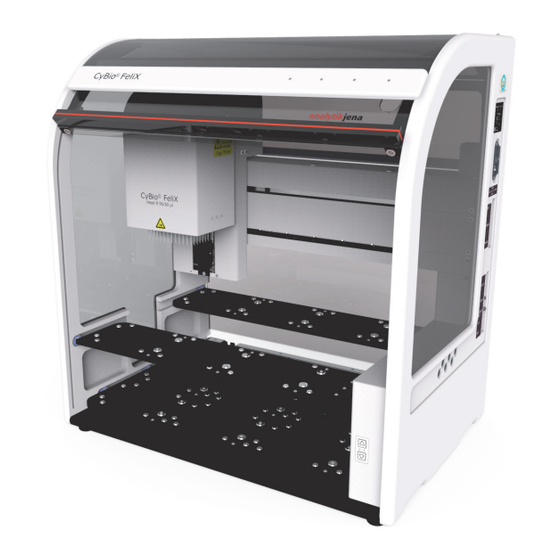
Technical Description Technical Description Setup/Components ® 4.1.1 CyBio FeliX – Overview Variant with enclosure/blind Fig. Basic unit Enclosure with blind → “Enclosure with Blind” on page 27 Upper Decks Lower Deck → see "Decks” on page 28 Legs Operating state indicator → “LED – Operating State Indicator” on page 31 Head mount → “Head Mount” on page 33 Barcode reader (connection)* see accessories manual Clamping lever → Fig. - Page 42 Technical Description Variant without enclosure/blind Fig. Variant without enclosure/blind Head mount → see "Head Mount” on page 33 Barcode reader (connection)* see accessories manual Upper Decks Lower Deck → see "Decks” on page 28 ON/OFF switch → “Turning On (Readiness for Operation)” on page 47 Connection values sticker → “Summary Table of Operating Data & Conditions” on page 9 Connector panel → “Connector panel”...
-
Page 43: Nameplate
Technical Description 4.1.2 Nameplate Fig. Nameplate Fig. Nameplate Nameplate specifications: Manufacturer details Product designation details (type designation, tradename) Identification code (model/serial number) Year of manufacture 4.1.3 Enclosure with Blind The enclosure protects operating personnel from danger by mechanically moving as- semblies, as well as samples, chemicals, etc. The enclosure may be complemented by an optional decontamination device (UV)*. The blind are part of the enclosure – their front face consisting of transparent perspex, in order to enable the operator to observe running processes. The purpose of the blind is to prevent physical interference with the pipettor’s move range. All currently running move will stop if the blind are raised. Once the blind have been lowered (closed) again, initially triggered move (of decks and pipetting head) will resume. The blind position is monitored and signaled by an operating state indicator (LED) → “LED – Operating State Indicator” on page 31. 1 With enclosure/blind. 2 Without enclosure/blind. -
Page 44: Decks
Technical Description 4.1.4 Decks Fig. Deck positions Please note the following position assignments: Deck A (lower deck): positions 1 – 6 Deck B (upper rear deck): positions 7 – 9 Deck C (upper front deck): positions 10 – 12 The purpose of deck move is to transfer microplates, reservoirs or accessory items into a required position. Upper level decks are intended for microplates and reservoirs Lower level decks are intended for accessories and tips Further information: → “Deck Configuration” on page 55. ® The upper level decks (decks B and C) of the CyBio FeliX are intended for receiving or ® dispensing of CyBio RoboTipTrays, for depositing the protective magazine as well as all types of micro plates and reservoirs in SBS format. Sign of intended use Movements are always performed without force acting on the upper level decks! NOTICE Dangerous situation – potential consequences: Material damage! On the upper rear deck (Deck B → Fig. 9) a height of 70 mm [→ see "Deck heights (In- strument with 70 mm Height –... - Page 45 Technical Description In the case of receiving/dispensing with the action of force there is a danger of permanent deformation of the upper level decks – for example if it is intended to pick up tips from tip boxes. Procedures of this kind are not permitted! On the upper level decks (Decks B and C) the raster (spacing between the deck posi- tions) is optimized for quick dispensing between micro plates (height[s] in acc. with SBS standard). If it is intended to use accessories on the upper level decks that are adjacent higher than micro plates that are lying on “Zero” deck level, height observation is required because of the optimized raster. NOTICE Dangerous situation – potential consequences: Material damage! If no height observation/adjustment is performed, there is the danger of collisions of the pipetting head with the accessories on the neighboring deck positions! Deck heights (Instrument with 55 mm height – Deck B/C) Fig. 10: Heights – Deck A, B and C Please see the illustration and the following table for detailed information: Table 10: Compilation Deck Height Description Command 115 mm Height...
- Page 46 Technical Description Deck heights (Instrument with 70 mm Height – Deck B/C) Fig. 11: Heights – Deck A, B and C Please see the illustration and the following table for detailed information: Table 11: Compilation Deck Height Description Command 115 mm Height 110 mm Usable height (accessories) B 70 mm Height 65 mm Usable height (labware) All tip types (except 1000 μl tips) All tip types (including1000 μl tips) 45 mm Usable height (labware)
-
Page 47: Led - Operating State Indicator
Technical Description 4.1.5 LED – Operating State Indicator LED – operating state indicators/arrow buttons / Fig. 12: LED – operating state indicators/arrow buttons Located on the pipettor’s front panel are operating state indicators to provide operating personnel with information about the current system state. They can be seen from the outside when the blind are down (closed). Table 12: Red/green LED Display Operating state GREEN System is ready for action. Can be operated via control commands entered at the PC. GREEN/BLINKING System is in operation and works on a (by external control) specified procedure. System reports an error. RED/BLINKING Errors will be signalled via red-flashing code → “LED Blinks –... - Page 48 Technical Description LED – operating state indicators/pushbutton Fig. 13: LED – operating state indicators/pushbutton Located on the pipettor’s front panel are operating state indicators to provide operating personnel with information about the current system state. They can be seen from the outside when the blind are down (closed). The upper LED displays the operating status – the lower LED provides an extra pushbutton function for manual operation. Table 14: Upper LED Display Operating state GREEN System is ready for action. Can be operated via control commands entered at the PC. GREEN/BLINKING → “Pipetting Head Movement in Z-Direction” on page 53 System reports an error → “LED Blinks – red” on page 77. Table 15: Lower LED Display Operating state...
-
Page 49: Head Mount
Technical Description 4.1.6 Head Mount Fig. 14: Head mount Guideways Electric connection point Clamping lever Please note: The clamping lever (Pos. 3, → Fig. 14) must be transferred into front position when no there is no fixed pipetting head (a pipetting head may not be pushed in, unless the clamping/tightening lever is in this position; transfer clamping lever into rear position on completion of action). ® CyBio FeliX 2018... -
Page 50: Pipetting Head Versions
Technical Description 4.1.7 Pipetting Head Versions* For pipettor operation, the following pipetting head versions are available: ® CyBio FeliX pipetting head T ® CyBio FeliX pipetting head R CHOICETM pipetting head NOTE At the moment of this User Manual going to press there may be some pipetting head versions which are not yet included in the latest selling offer. ® CyBio FeliX pipetting head T ® This pipetting head provides a mechanism to mount CyBio TipTrays (manual top exchange). ® CyBio FeliX pipetting head R This pipetting head provides a mechanism for automated mounting of ® CyBio RoboTipTrays and liquid handling adapters. CHOICETM pipetting head This pipetting head provides a mechanism to facilitate the automated mounting of ... -
Page 51: Fan
Technical Description 4.1.8 Fig. 15: Rear side view (rear panel removed, fan marked) The fans are located in the rear position of the system. NOTICE The pipettor must be installed in a position that warrants adequate air exchange rates at any time. A safety clearance not less than 150 mm must be kept. ® CyBio FeliX 2018... -
Page 52: Connector Panel
Technical Description 4.1.9 Connector panel Located on the rear panel are the various terminals and interfacing ports. Fig. 16: Terminals USB jack type B Sub-D jack 9-pole (COM IN) Networking jack* Fig. 17: Terminals Sub-D 9-pole plug (COM OUT) M8 4-pole plug (E-STOP IN) M8 4-pole jack (E-STOP OUT) I/O 1 I/O 2 ® 2018 CyBio FeliX... - Page 53 Technical Description Table 16: Communication interfaces → Fig. 16 on page Description USB Communication interface (HOST-PC) COM IN RS 232 Communication interface (HOST-PC) ETHERNET Network connection 1 Communication interfaces. NOTE Please consult the manufacturer (regarding special interfaces). Table 17: Special interfaces → Fig. 17 on page Description COM OUT Forwarding interface to another device E-STOP IN Connection for an opening switch element (STOP-function) E-STOP OUT Socket for second device I/O 1 Signal interface (Accessories) I/O 2 Signal interface (Accessories) ...
-
Page 54: Mode Of Operation
Technical Description Mode of Operation ® The CyBio FeliX works based on the principle of air displacement. The pipette tips and their internal seals create air spaces. Pistons perform move within these air spaces. They are powered by a common drive. NOTE Piston move creates negative pressure or positive pressure, thus causing liquid to be aspirated or released. Upon reaching pressure equalization state, the current process is completed. The time required to reach this state depends - among other factors - on the properties of the liquid being handled. Operating Modes The following modes are available for operation: PC control → “Software-Controlled Operation” on page 56 Manuel mode (Control of the Z-direction by means of button) → “Pipetting Head Movement in Z-Direction” on page 53 ®... -
Page 55: Packaging, Transportation & Storage
Packaging, Transportation & Storage Packaging, Transportation & Storage Safety Notes CAUTION There is danger of physical injury or material damage! Always hold it at the bottom of the frame structure. Make sure that all shipping retainers are actually in place. NOTICE Environmental influences, mechanical shocks or formation of condensed water may destroy individual system components! Adequate precautions should be taken to protect all components from environmental impacts, mechanical shock or formation of condensed water during transportation or shipment! Temporary open-air storage of the system is forbidden! NOTICE Improper packaging is likely to cause damage to the system! Use only original packing for transportation and shipment of the system and its accessories. NOTE You are advised to contact Analytik Jena AG service personnel in case of doubt as to the proper packing or transportation of the system. ® CyBio FeliX 2018... -
Page 56: Packaging
Packaging, Transportation & Storage Packaging 5.2.1 Placement of shipping retainer 1. Please check that head mount is in mid-range position. 2. Check that lower deck has moved to rearmost position and upper decks are fully apart. 3. Install shipping retainer for the decks. 4. Install shipping retainer for head mount. 5. Close blind 1 Does not apply for enclosure-less model (for example 30-5015-500-24). Prescribed shipping fixtures are duly installed. ® 2018 CyBio FeliX... -
Page 57: Packaging
Packaging, Transportation & Storage 5.2.2 Packaging ® CyBio FeliX shipping case: Plywood case with padding plate (approx. 1000 x 740 x 800 mm) Padding bars Bag with related screws and washers 1. Place pipettor on the bottom of the shipping case. 2. Please note recess pocket for handle. 3. Use protective foil for covering up. 4. Put on upper shaped pieces. 5. Safely store accessory items – provide adequate padding for free spaces. 6. Close shipping case and affix warning stickers and shock indicators. The system is in completely packed condition. ®... -
Page 58: Storage
Packaging, Transportation & Storage 5.2.3 Storage ® If the CyBio FeliX is not installed immediately after arrival of product shipment or not required for a longer period of time, it should preferentially be stored in its original packing case. Climatic requirements on facilities for system storage are as follows: Temperature range: -10 °C to +50 °C Permissible relative air humidity: ≤ 85 % at 30 °C, no formation of condensate ® 2018 CyBio FeliX... -
Page 59: Routine Start-Up Procedure
Routine Start-Up Procedure Routine Start-Up Procedure Site Requirements 6.1.1 Installation Requirements The room which is selected for installation must meet the following environmental requirements: Temperature range: +15 °C to 35 °C Permissible relative air humidity: ≤ 75 % at 35 °C, no formation of condensate The atmosphere inside the operating room should be dust-free to a maximum possible degree, free from drafts and free from etching vapours. You are prohibited from smoking in the operating room. For pipettor site selection, the following rules should be observed: The operating room must have a stable, horizontal, dry and vibration-free floor. Do not install the system directly at doors or windows nor close to sources of electromagnetic interference. Prevent direct exposure to sunlight and radiation emitted by heaters. Provide air conditioning for the room if necessary. Provide easy access to all system parts at all times and do not obstruct ventilation slots by placing other equipment or fixtures on such inlet/outlet positions. Allow enough time for the system to adjust to the installation site temperature, especially where storage and installation are in different locations. Pay attention with a choice of the system location, in any case, to the fact that the on/off switch is to be reached any time easily. NOTICE Failure to observe these installation requirements/rules may impact the correct system ... -
Page 60: Energy Supplies
Routine Start-Up Procedure 6.1.3 Energy Supplies WARNING In the event of a break in protective conductor wiring, there is life-threatending danger due to electrical shock! Insert the main power plug only into a mains socket with a grounded PE contact! Make sure that the protection effect is not rendered ineffective by extension cables without a PE conductor or by the use of a voltage regulating transformer! CAUTION Operation at a mains voltage level or frequency other than specified on the label may result in destruction of the pipettor! Make sure that power supply specifications in the operating room do agree with those on the label! You are prohibited from starting the system up if there is a mismatch in specifications. The system requires a single-phase alternating current net for normal operation. The system includes a wide-range power pack. It is rated for AC voltage levels of 100 – 240 V and a frequency of 50/60 Hz. You should make absolutely certain that la- bel specifications are actually met and power is supplied with values as indicated on the label. ® 2018 CyBio FeliX... -
Page 61: Initial Start-Up & Configuration
Routine Start-Up Procedure Initial Start-Up & Configuration Because of the system's complexity and to guarantee its failsafe function, work for installation, initial start-up and configuration on your premises may be performed by none other than Analytik Jena AG service personnel or duly authorized expert techni- cians. Initial start-up essentially includes: Installation and adjustment of system components Providing cable connections and connecting power supply cables Software installation (factory-performed) and configuration Briefing and on-the-job training Check – within the scope of the start-up procedure – that the on/off switch or plug are easily accessible any time. WARNING Not slightly accessible on/off switch (or plug) hinder the prompt system disconnection in dangerous situations. ® CyBio FeliX 2018... -
Page 62: Function Tests
Routine Start-Up Procedure Function Tests NOTE On completion of manufacturing, the test procedures described in this chapter are carried out in standardized conditions (test & metrology room). Resulting test reports are included in the scope of delivery. 6.3.1 Precision Test Testing for variation coefficient CV (percentage standard deviation) is performed using a 96-well or 384-well microplate with transparent flat bottom and dye solution. A suitable vertical photometer serves as the measuring tool. Its own precision must have been tested/verified and documented prior to measurement. NOTE Specific pipetting head specifications (and other advice regarding this test procedure) are contained in the special pipetting head manual. 6.3.2 Accuracy Test Accuracy defines the degree of agreement between a measured dispensed volume (mean value of all measurements in a 96-well or 384-well microplate) and a specified (target) volume. NOTE Specific pipetting head specifications (and other advice regarding this test procedure) are contained in the special pipetting head manual. 6.3.3 Leak Test Leak testing is necessary to ensure that the pipetting head does not leak liquid. A leak test is performed drawing a particular volume of dye solution into the pipette tips and watching their liquid level over a time of 30 minutes. NOTE Specific pipetting head specifications (and other advice regarding this test procedure) are contained in the special pipetting head manual. ® 2018 CyBio FeliX... -
Page 63: Operation
Operation Operation Turning On (Readiness for Operation) 1. Check for correct connection of power cord to line power supply. 2. Make sure that the blind are down 3. Transfer On/Off switch (on the right lateral side) into position "I" (→ Fig. 18). 4. Follow operating indicator (LED) states: Red (steady/blinking): Internal error is reported (error analysis → „LED Blinks – red” on page 77). Green (steady): Reports completion of init routine and readiness for operation. 5. Make sure that PC is correctly linked up with the system, power is available and control software session has been triggered. Fig. 18: On/Off switch The pipettor is ready for action (insert head if necessary) and to carry out commands of the computer controller. -
Page 64: Restoring Readiness For Operation After Break Events (E.g. Power Failure)
Operation Restoring Readiness for Operation after Break Events (e.g. Power Failure) Following an unforseeable break in operation for example, a power fail situation, or switching off or interrupting the PC connection, you may restore the pipettor to proper operating condition. At first you should make sure that restoration to operating condition will imply no danger and carry out the following steps in this same order: Move pipetting head out of danger zone Shift pipetting head in Z-direction (using PC controller or manual → „Pipetting Head Movement in Z-Direction” on page 53) and/or move pipetting head in X-direction (manual). Remove labware Remove labware as necessary. Remove residual liquid from tips Turn power off. Turn it on again after a short while. Restore PC to operating condition ... -
Page 65: Replacement Of Pipetting Head
Operation Replacement of Pipetting Head CAUTION Dangerous situation! There is danger of crushing/pinching during move to raise or lower the blind 1 Does not apply for enclosure-less model (for example 30-5015-500-24). CAUTION Dangerous situation! Danger of crushing/pinching – the pipetting head weighs approximately 6 – 7 kg. Hold the pipetting head with both hands. Installation and replacement of a pipetting head may be performed with the pipettor in powered on or powered off. Make sure that all system units are properly acclimatized (head and system have same temperature level at installation site). The head mount (X-axis) should be in mid-range position (can be shifted manually). The head mount (Z-axis) should not be in uppermost position. For head replacement, you are recommended to select an offset position 30 mm below uppermost vertical position. NOTICE Make sure that the cover magazine (transport protection; OL3316-11-200) was at- tached before removing the pipetting head because the head must only be put down when resting on this protective cover. This is essential for preventing damage to the device! ® CyBio FeliX 2018... -
Page 66: Mounting The Pipetting Head
Operation 7.3.1 Mounting the Pipetting Head 1. Make sure that the head mount is in mid-pipettor position, not in uppermost vertical position. 2. Swing clamping lever around into front position. Fig. 19: Head mount (with clamping lever in front position) 3. Mount pipetting head. Fig. 20: Insertion of pipetting head 4. Secure pipetting head, i.e. swing clamping lever back again. Fig. 21: Pipetting head ready for operation 5. Check for proper fixation and move blind down to close 6. -
Page 67: Replacement Of Pipetting Head
Operation 7.3.2 Replacement of Pipetting Head 1. Install transportation lock. 2. Raise blind to open 3. Swing clamping lever into front position. Fig. 22: Pipetting head (fixed) 4. Take the pipetting head off. Fig. 23: Removal of pipetting head Fig. 24: Head mount (with clamping lever in front position) 5. Check for proper fixation of the head and close the blind 1 Does not apply for enclosure-less model (for example 30-5015-500-24). 2 Does not apply for enclosure-less model (for example 30-5015-500-24). ®... -
Page 68: Manual Operation
Operation Manual Operation CAUTION There is danger of crushing or pinching! Likely consequences: light or minor physical injury. 7.4.1 Motion Axis Fig. 25: Directions of move and coordinate pattern view Pipetting head The pipetting head is capable of motion in X-direction and Z-direction. Decks The decks are capable of motion in Y-direction. Available options for manual/electrical move are as follows: Table 18: Manual and electrical move capabilities Direction Pipetting head Decks manual/electric – – manual/electric electric –... -
Page 69: Pipetting Head Movement In Z-Direction
Operation 7.4.2 Pipetting Head Movement in Z-Direction Pipetting head movement (Variant arrow buttons /) CAUTION Dangerous situation! Although movement is performed slowly, refrain from placing your hands or fingers in the inner pipettor space as long as drive mechanisms are in action. Is only available if the blind is closed. This function is intended to move the pipetting head in Z-axis direction, in order to remove or replace the head. 1. Blind is closed. 2. Press arrow button or (> 3 seconds – green operating status indicator blinks). 3. Release button. NOTE If the green operating status indicator blinks, the “Pipetting head move in Z-direction“ mode has become active. - Page 70 Operation Pipetting head movement (Variant LED-button) CAUTION Dangerous situation! Although movement is performed slowly, refrain from placing your hands or fingers in the inner pipettor space as long as drive mechanisms are in action. Is only available if the blind are down and/or the external E-STOP* in open/broken state. This function is intended to allow move in Z-axis direction, in order to be able to move the pipetting head up as much as necessary to remove or replace the head. 1. Check that LED (YELLOW) lights steady → Fig. 13 on page 32. 2. Press LED (YELLOW) (> 3 seconds – yellow/off). 3. Release LED (YELLOW. The “Pipetting head move in Z-direction“ mode has become active if the LED (YELLOW) lights and the green operating status indicator blinks. 4. Press LED (YELLOW) and keep it depressed – watch pipetting head as you do this (head performs move).
-
Page 71: Deck Configuration
Operation Deactivation of teach modus (only for 30-5015-100-24) 1. Press LED (YELLOW) (or lower blind until closed) – (yellow off). Deactivation of teach modus (only for 30-5015-401-24) 2. Press LED (YELLOW) (or put external safety device out of emergency stop mode) – (yellow off). For re-activation, the sequence of actuation steps needs to be repeated. Deck Configuration ® The CyBio FeliX pipettor includes three decks (A, B and C). These are arranged at two → different height levels ( „Motion Axis” on page 52). The purpose of deck A (lower level) is to provide accessories, for example, tips and tip wash station. The maximum allowed height of labware on this deck is 110 mm. Deck B (upper level rearside area) and deck C (upper level front area) are intended for mircoplates and reservoirs with a maximum height of 65 mm. ® CyBio -TipBoxes are specified for use on deck A only. For column-by-column processing, you are recommended to use positions 1, 2, 4 or 5 ... -
Page 72: Software-Controlled Operation
Operation Software-Controlled Operation ® ® CyBio FeliX operation runs under the control of CyBio Composer software to facili- tate laboratory routines to be compiled easily and in an express procedures (for explanations, refer to the table below, the following manual sections or the software help menu). 7.6.1 General Commands (Summary Table) Symbol Function Explanation – A given volume is aspirated. This setting Ansaugen defines the amount of liquid that will be taken Aspirate in during a cycle. The permissible volume range depends on the head type and the type of selected tips – Optionally, an overstroke volume may be defined – A given volume is dispensed in standard mode Ausstoßen or with residual eject/blow-out function. Dispense – Pistons move into their zero-positions Kolben in Nullposition Piston to zero position –... - Page 73 Operation Symbol Function Explanation ® – CyBio TipTrays are mounted by electric- Anbringen powered move (manual replacement/ Load exchange) – Automated mounting of ® CyBio -RoboTipTrays and liquid handling adapters in a selected position ® CyBio -TipBoxes – Picking up of tips from ® – CyBio TipTrays are released by electric-pow- Entfernen ered move (manual replacement/exchange) Unload – Automated placement of ® CyBio -RoboTipTrays and liquid handling adapters in a selected position – Discarding of tips into waste – Selection of components installed at the Werkzeuginformation ...
-
Page 74: Removal Of Transportation Lock
Operation 7.6.2 Removal of Transportation Lock Pipetting head R Once the pipetting head is mounted, its transportation lock needs to be removed in or- der to be able to achieve readiness for operation. Use software commands to proceed as follows: 1. Check that power is available to the pipettor and the PC (turned on state). 2. Check pipetting head for correct mounting. 3. Select “Remove“ command. 4. Define a position on deck A and make setting for Support. Fig. 26: Commands Fig. 27: Settings (Set tool info) 5. Trigger Z-axis up-motion (command “Vertical drive“). 6. Trigger method and remove transportation lock after place-down working step. Fig. 28: Settings for placing down ® 2018 CyBio FeliX... -
Page 75: Preparing For Head Replacement/Turning Off
Operation 7.6.3 Preparing for Head Replacement/Turning Off NOTICE Dangerous situation! Remember to install the transportation lock before you replace a pipetting head. This is necessary to prevent cases of material damage. Proceed as follows: 1. Select “Load“ command. Fig. 29: Components window 2. Make setting as indicated below: Fig. 30: Mounting the transportation lock ® CyBio FeliX 2018... -
Page 76: Move In X-, Y- & Z-Direction
Operation 7.6.4 Move in X-, Y- & Z-Direction In software-supported operation control mode the pipetting tips can be moved into position directly over a plate or reservoir by triggering a “Move to deck position” command. The Z-axis will be in uppermost position. Select the reference point for the Z-axis as follows: Topmost vertical position (Oberste Vertikalposition) Deck position (Deckposition) or Plate adapter position (Plattenadapterposition) Use a “Move to deck position“ command to position the Z-axis in relation to the lab- ware. Use a “Vertical drive” command to position only the Z-axis at a particular height. Move to deck position – Select position referenced to X- and Y-axis – Z-axis: uppermost vertical position – Shift selectable for each axis Fig. 31: Positioning window Move to labware – Select position referenced to X-, Y- and Z-axis –... - Page 77 Operation Fig. 32: Interactive positioning screen for setting of shift values With the help of parameter “Offset“it is possible to address positions in an off-center part of a well (e.g. dispensing of liquid in a near-edge position or work with assymetric plates such as addressation of the reservoir of a protein crystallization plate). The mid-well position corresponds to zero-point of the coordinate system in these cases. For move to the left, X takes on a negative value. Example: -3.5 mm. For rearward move, Y becomes positively signed. Example: 3.5 mm. Following entry of these coordinate positions, the pipette tips will be positioned near the upper left edge. Depending on the type of plate (number of wells, geometry of wells) these values may vary and may have to the adapted individually. On clicking of the arrow in the right input line part a menu window will open → Fig. 32. Values may be directly entered or set/edited with the help of the arrow keys in this menu. Once a desired value has been reached, move to the particular position can be triggered by pressing the “Move“ control button. A click onto “OK“ will acknowledge this set- ting – on selection of ”Cancel“ the initial setting will be preserved. ® CyBio FeliX 2018...
-
Page 78: Load/Unload Tips - Pipetting Head T
Operation 7.6.5 Load/Unload Tips – Pipetting Head T For pipetting heads of type T, tip replacement is always performed in manual mode. However, some software commands are still required to release or fix the tips or the transportation lock. This is achieved with the help of a “Load“ or a “Unload“ command, respectively. ® Only the specified CyBio TipTrays are used in all cases (refer to chapter ”Accessories“ in the pipetting head manual). To perform tip mounting/tip replacement, proceed as follows: 1. Select command “Load“/“Unload“. 2. Make parameter settings as necessary (head type, tips, etc.). Fig. 33: Components window 3. Trigger method and perform manual replacement. Fig. 34: Manual replacement method ®... -
Page 79: Tip Mounting/Tip Replacement - Pipetting Head R
Operation 7.6.6 Tip Mounting/Tip Replacement – Pipetting Head R In the case of pipetting heads of type R, tips are mounted and placed down in automatic mode. For (down) placement of pipetting tips there must be a suitable empty support/holder available on deck A (lower level, optional on deck C). To be able to perform mounting of pipette tips, a suitable holder with a corresponding ® CyBio RoboTipTray must be available on deck A. Pipetting heads of type R are capable of loading LH adapters for column-by-column or line-by-line processing, including single-channel processing in addition. The CHOICE™ head is exclusively extended for operation with CHOICE™ adapters. Only column-by-column, line-by-line and single-channel processing capability are available for microplates. As a necessary precondition for mounting of a liquid han- dling adapter, a suitable support with LH adapter must have been placed on deck A. Further information: Refer to chapter ”Accessories“ in the pipetting head manual Refer to Table 25, “Liquid handling-/CHOICE adapter,” on page 94 Refer to Table 26, “Support for LH-adapter/tips,”... - Page 80 Operation Mounting pipette tips, liquid handling adapter and CHOICE adapter An LH adapter or CHOICE -adapter is mounted in essentially the same way as ® CyBio RoboTipTrays – see → Fig. 38 (example of parameter inputs). For working with LH adapters, pipette tips of the specified type must be mounted. To be ® able to do this, a corresponding CyBio -TipBox or a support for 1000 μl tips* must be positioned on deck A. After mounting an adapter, the information (on the attached pipette tips) must be set as follows: 1. Select „Set tool info“ command. 2. Make a selection under the appropriate adapter type. If an adapter was mounted without pipette tips, choose the property "tips (tips)" "No Add-On (No add-on). A cycle to pick up pipette tips from a box/rack and mount them can be triggered using the “Load” → command. It contains all required input parameters Fig. 38 Make sure that compatibility with LH adapter is guaranteed for your selected type of pi- pette tips → page 65. Fig. 37: Components window Fig.
- Page 81 Operation Fig. 39: Pipette tip mounting method (example) Mutual compatibility of pipette tips and LH adapters NOTE The working volumes which are specified herein may me software-limited depending on the installed type of pipetting head. The same applies to pipette tips with filter (filter tips) that provide only little net volume. Table 19: Summary table regarding compatibility Type of tips Designation ® CyBio -TipRack 96/1000 1-/8-/12-Channel CHOICE Adapter; 10 μl – 1000 μl μl ® CyBio -TipBox 96/250 μl 1-/8-/12-Channel CHOICE Adapter; 10 μl – 1000 μl 1-/8-/12-Channel Adapter; Head R 96 ®...
- Page 82 Operation Remove of pipette tips, liquid handling adapter and CHOICE -adapter A CHOICE adapter or liquid handling adapter may be placed down even with tips if a suitable holder is used (this procedure is recommended where the pipette tips are to be used repeatedly). Otherwise, the pipette tips need to be placed down in a first step, which may be fol- lowed by placing down of adapters as necessary. In either case, a „Unload“ command must be selected. To be able to place down tips, an adapter type must be selected (for placing down an adapter – a head type). Fig. 40: Components window For placement of tips, the involved labware and related positions must be defined – for placement of an adapter, a particular holder needs to be defined. Fig. 41: Example: Placement of tips Fig. 42: Placement of LH adapter ® 2018 CyBio FeliX...
-
Page 83: Pipetting
Operation 7.6.7 Pipetting Each piston movement performed as part of an aspiration or dispensing cycle creates under pressure or overpressure. To be able to reach a required position, it is necessary to wait for pressure equalization state inside the tips. This is accounted for by the software command “Break“. The required amount of break time depends, among other factors, on the properties of liquid being processed. A wait- ing time of 2 seconds is adequate for the large majority of acqeous solutions. A full volume cycle includes the commands “Aspirate“, ”Dispense“ (sub-volumes where necessary), a Blow-out step (combined with ”Dispense“ or separately) and a “Pis- ton to zero-position“ command. For liquid transfers, two different methods are available – pipetting of a single volume and reverse pipetting. NOTICE Dangerous situation! Perform move into zero-position always without any liquid, in order to prevent damage! Pipetting (single volume) Proceed as follows: 1. Aspirate without overstroke/additional stroke. 2. Dispense with residual ejection/blow-out. 3. Move into zero-position (without liquid). Fig. 43: Sequence of actions ® CyBio FeliX 2018... - Page 84 Operation Reverse pipetting (single volume or subvolumes) The term ’Reverse pipetting’ means that a defined volume plus an additional extra volume are taken in with overstroke and such defined volume is exactly dispensed again thereafter. This procedure can be repeated as necessary. A certain residual volume remains within the tip to the dispensed into a reservoir at the end of the process. Reverse pipetting is particularly suited where small volumes or foaming or viscous liquid samples have to be processed. Where several sub-volumes need to be dispensed, you should take in an additional ex- tra-volume with subsequent dispensing back into its source. Proceed as follows: 1. Aspirate with overstroke. 2. Dispense (single volume or subvolumes). 3. Dispense remainder from overstroke volume. 4. Perform move into zero-position (without liquid). Fig. 44: Sequence of actions ® 2018 CyBio FeliX...
-
Page 85: Turning Off
Operation Turning Off To turn the pipettor off, proceed as follows: 1. Wait for pipettor to finish all currently running work routines. 2. Place the pipette tips and/or LH-adapter down using the function described on → „Remove of pipette tips, liquid handling adapter and CHOICE -adapter” on page 66. ® 3. Use On/Off-switch on the lateral side to turn the CyBio FeliX off. The operating state indicator on the front panel extinguishes. 4. Close software control session and turn the PC off as may be appropriate. ® The CyBio FeliX has been shut down. ® CyBio FeliX 2018... - Page 86 Operation ® 2018 CyBio FeliX...
-
Page 87: What To Do If
“What to do if...“ “What to do if...“ Safety Notes NOTE Refrain from unauthorized repair work, notably, repair work on the product. This may render potential claims for warranty null and void. WARNING Danger as a result of electric voltage! Observe all safety rules when you inspect cabling for possible faults. System does not work Check all potential fault sources on occurrence of a fault. If problems are found to persist after this check or on identification of an undescribed fault, you should notify the Customer Service of Analytik Jena AG. 8.2.1 Further Errors Error Cause Action for removal Product does not Mains plug was inserted Inspect line power connector work although into the power socket or and plug in correctly. -
Page 88: Error Codes
“What to do if...“ Error codes Error/Error code Cause Action for removal E 1 Spannmechanismus defekt Notify your service contractor or Tightening mechanism contact Analytik Jena AG. defective E 2 Unbekannter Kopftyp Remove pipetting head. Turn Unknown head type power supply off. Mount pipetting head in correct position. Turn power supply on again and trigger blank soft-ware method for initialization. If the error persists, you should contact your service contractor or Analytik Jena AG. E 3 FRAM Zugriff Notify your service contractor or fehlgeschlagen contact Analytik Jena AG. Error accessing FRAM E 4 Spitzen möglicherweise Use software commands to nicht angezogen remove pipette tips. Mount Tips are possible not pipette tips again. If the error tightened persists, you should containt your ... - Page 89 “What to do if...“ Error/Error code Cause Action for removal E 10 Das auszuführende Firm- Notify your service contractor or ware-Kommando ist nicht contact Analytik Jena AG. implementiert The firmware command to be executed is not implemented E 17 Fahrfehler des Kolbenant- Notify your service contractor or riebes contact Analytik Jena AG. Piston drive error E 18 Ein Firmware-Kommando Notify your service contractor or erwartet weitere Parame- contact Analytik Jena AG. A firmware command expects additional parameters E 19 Unbekanntes Spitzen- Notify your service contractor or magazin contact Analytik Jena AG. Unknown tip magazine E 20 Ausführung durch Retrigger the method. Anwender abgebrochen Execution was cancelled by ...
- Page 90 “What to do if...“ Error/Error code Cause Action for removal E 36 Kopf nicht arretiert Mount pipetting head in correct Head not clamped position. Trigger blank software method for initialization. If the error persists, you should contact your service contractor or Analytik Jena AG. E 37 Liquid-Handling-Adapter Mount liquid handling adapter nicht vorschriftsmäßig in correct position. Trigger eingesetzt blank software method for Liquid handling adapter initialization. If the error persists, not properly inserted you should contact your service contractor or Analytik Jena AG. E 38 Liquid-Handling-Adapter Notify your service contractor or defekt contact Analytik Jena AG. Liquid handling adapter not working E 39 Unbekannter Liquid-Han- Turn power supply off. Turn on dling-Adapter the power again and start a Unknown liquid handling ...
-
Page 92: Fault Removal Instructions
“What to do if...“ Fault Removal Instructions 8.4.1 Replacement of Inlet Fuse(s) WARNING There is danger of exposure to electric voltage! Always detach the power supply cable from the line power socket before you replace a fuse. Check for absense of voltage in the pipettor. Fig. 45: Fuses (two) in combi seal at the back of the pipettor Description Type/Rated specs Line power fuse T 4 A, 250V AC, 5x20 mm 1 High Breaking Capacity Fuse → „Summary Table of Operating Data & Conditions” on page 9 Replacement of system fusing 1. -
Page 93: Led Blinks - Red
“What to do if...“ 8.4.2 LED Blinks – red Identified errors will be signalled via red-flashing code as follows: Flashing code Type of identified error/comment Single flash Error on internal motor bus 2-flash Error E-STOP system 3-flash Error blind 4-flash Error external E-STOP system 5-flash Error E-STOP engine power off 6-flash Error E-STOP engine power off 10-flash Non-conformity in data memory for version number 11-flash Failure to read data memory for version number 12-flash Failure to read data memory for pipettor configuration 13-flash Data memory 14-flash Synchronization error Each flashing code will continuously repeat after some break. Proceed as follows in this case: 1. Turn system power off and restore power – after a short break. 2. - Page 94 “What to do if...“ ® 2018 CyBio FeliX...
-
Page 95: Maintenance & Care
Maintenance & Care Maintenance & Care Safety Notes WARNING Please note that physical contact with voltage-carrying system parts may lead to body injury or even death! Turn system power off and detach power cable from the line power socket before you proceed to any kind of work for maintenance or care! Take adequate precautions to protect the system from accidental restoration of power! Operating personnel are prohibited from performing work for maintenance, repair or adjustment of voltage-carrying system parts! Maintenance, repair or adjustment of system modules under electrical voltage may only be carried out by a qualified electrician! CAUTION Penetrating liquid may cause material damage to electrical and electronic components! Make sure that no liquid can penetrate into the inner space during any kind of maintenance or care. NOTE Intervention to mechanical or electronic parts in the inner ® CyBio FeliX space may not be performed by anyone other than customer service per- sonnel or specially authorized expert technicians. ® To ensure that your CyBio FeliX is kept in a state of optimal adjustment and faultless function over a longer period of time, we recommend the conclusion of a service/maintenance contract with Analytik Jena AG Jena. ® CyBio FeliX 2018... -
Page 96: Maintenance Work
Maintenance & Care Maintenance Work Perform care and maintenance work tasks at regular intervals as specified herein and following these general advisory rules: Contamination and natural wear of modules give rise to increased strain levels and, hence, an increased probability of failure. Check for signs of wear and tear on assemblies under mechanical strain and initiate necessary replacements promptly on identifying a case of wear and tear. All systems parts capable of manual or motorized move are subject to natural wear. Similarly, electronic components have no unlimited lifetime. NOTE Dirt, e. g. dried-on liquid, may increase wear dramatically in some cases. Always maintain clean working conditions! ® 2018 CyBio FeliX... -
Page 97: Overview
Maintenance & Care 9.2.1 Overview Table 20: Maintenance summery table Maintenance action Maintenance intervals Weekly Monthly Half-yearly → “Cleaning the basic unit (including decks)” on page 83 Replace used tips as neces- sary or at least once in a week Empty and clean tip waste box* as neces- sary or at least once in a week Clean all liquid-holding vessels* and the outside of tubes* with disinfectant → “Perform Head Mount Mainte- nance”... -
Page 98: Maintenance/Inspection Instructions
Maintenance & Care Maintenance/Inspection Instructions NOTE When working on the device or on accessories it is recommended to wear personal pro- tective equipment (PPE). The exterior of the device and any control elements located on the exterior must not be touched with gloves which were used for working on the device interior and which may have been contaminated during this work! The scope of the safety labeling (as a mandatory component of accident prevention measures) is shown in the chapter → “Safety Labeling Provided at the System” on page 13. NOTICE Remove contamination and damage immediately! However, never use the following substances for cleaning purposes: Solvents (thinner) Cleaning powder Corrosive or flammable agents (e.g. gasoline, acetone) Phenols or caustic alkaline solutions These cause corrosion on the device surfaces. Carefully observe the information regarding this topic in chapter → “Chemical resis- tance” on page 21. Processing biological samples of a risk group Take particular care when using the device for processing biological samples of a risk ... -
Page 99: Cleaning The Basic Unit (Including Decks)
Maintenance & Care 9.3.1 Cleaning the basic unit (including decks) NOTICE Use a lint-free cloth with a disinfecting / cleaning agent which is recommended by WHO ® guidelines and which is not excluded in this manual (such as Incidin Liquid, produced ® by ECOLAB) for cleaning the CyBio FeliX and any accessories which may only be treat- ed using the wipe disinfection method (see chapter → “Chemical resistance” on page 21). To prevent damage on the device, the interior and exterior parts must NEVER be cleaned / decontaminated using the spray disinfection method! NOTE Never treat surfaces in dry condition! Never apply on hot surfaces or on voltage-carrying electrical equipment. Procedure: 1. Remove the tips. 2. Attach the cover magazine (transport protection; OL3316-11-200). Fig. 46: Cover magazine (transport protection) attached ®... -
Page 100: Perform Head Mount Maintenance
Maintenance & Care 11. Wait until all cleaned surfaces have completely dried. 12. Insert the mains plug back into the power outlet and press the device switch to turn on the unit. The device is now ready for operation. Detach the cover maga- zine (transport protection), if attached. 9.3.2 Perform Head Mount Maintenance Fig. 47: Head mount Guideways Please note: 1. Guideways (rails) must be inspected (for clean condition, edge burr, warping, etc.) 2. An ultra-thin layer of silicon grease must be applied on the rail surfaces. Wipe off any excessive amount of grease. 9.3.3 Cleaning cones For security reasons and to ensure tightness, it is important that the cones of the liquid handling adapters are free of soiling when using these adapters. Therefore, the cones must be cleaned using a lint-free dry cloth in regular intervals (e.g. to remove dust). NOTE O-rings positioned on the cones must not be displaced or turned out of position! ® 2018 CyBio FeliX... -
Page 101: Replacement Of O-Rings
Maintenance & Care 9.3.4 Replacement of O-Rings ® CyBio FeliX operation involves O-rings (where a liquid handling adapter is required). They are subject to permanent mechanical stress through contact with the pipette tips. Accordingly, for reasons of safety and to ensure the absence of leakage, the cone O- rings must be replaced at regular intervals. Where a maintenance contract has been concluded, replacement of O-rings will be performed by Analytik Jena AG service per- sonnel as part of each on-site maintenance package. Generally, O-rings should be re- placed in the case of obvious signs of wear and tear. This can be done with tooling included in delivery. Preparation: 1. Turn system power off (→ “Turning Off” on page 69). 2. Take O-rings and push them one by one onto the O-ring guide rod. 3. Take O-ring guide rod with mounted O-rings, insert the rod into its designated opening and push it in until mechanical stop position. ® CyBio FeliX 2018... - Page 102 Maintenance & Care Removal of old O-ring: 1. Hold the O-ring mounting tool with its designated cone end facing forward, then push the tool with the groove at O-ring height in the direction of the cone. Then exert moderate pressure and finally remove the O-ring mount- ing tool and the O-ring from the cone. 2. If your attempt at O-ring removal fails, there is still an alternative method for removal of the O-ring. Turn the O-ring mounting tool around for this purpose. There is a tip provided on the side of the O- ring guide rod that can equally be used to remove the O-ring. To do this, press the tip against the O- ring and remove the ring. ® 2018 CyBio FeliX...
-
Page 103: Check For Correct Blind Function
Maintenance & Care Mounting the new O-ring 1. Turn the O-ring mounting tool until the O-ring guide rod faces toward the top, then slightly press against the cone. 2. Slowly push one of the string- threaded O-rings along the O-ring guide rod towards the cone until reaching the groove. Work can now be resumed in normal operating mode. 9.3.5 Check for Correct Blind Function To guarantee safe pipettor operation, the blind must be checked for proper condition. Proceed as follows: 1. Turn the pipettor on. 2. Trigger blind move and make sure that: – move runs easily/unobstructed – all currently running move is broken on raising of the blind 1 Does not apply for enclosure-less model (for example 30-5015-500-24). - Page 104 Maintenance & Care ® 2018 CyBio FeliX...
-
Page 105: Shutting Down
Shutting Down Shutting Down CAUTION There is danger of physical injury and damage to the system if cabling is removed in power on-state! Do not remove cables as long as they are energized! Make absolutely certain that power supply has been cut before you remove a cable! ® If the CyBio FeliX is not required for a longer period of time, perform shut-down ac- tion as described hereafter: 1. Remove the pipette tips; place liquid handling adapter(s) (if involved in operation) onto a suitable support. 2. Mount transportation lock at pipetting head (or have it mounted by expert). 3. Transfer the main power switch on the side panel into position "0". 4. Turn system power supply off (using main switch or socket bar for this purpose). 5. Disconnect line power cable from socket bar or line power socket. 6. Remove all microplates, reservoirs and accessories. 7. Clean and disinfect the pipettor and its components as described in handling instructions for the most recently used materials and substances. 8. Protect the system from sedimentation of dust. The system has been completely shut down. ® CyBio FeliX 2018... - Page 106 Shutting Down ® 2018 CyBio FeliX...
-
Page 107: Accessories & Spare Parts
Accessories & Spare Parts Accessories & Spare Parts NOTE The pipettor and its accessories are factory-matched to each other. Use only accessories recommended by the manufacturer. The manufacturer will refuse any warranty in the event of damage or function failure as a result of system operation with unspecified accessory items. 11.1 Accessories Further information: see Price list. 11.1.1 Pipette Tips NOTE Pipette tips are disposable (single use items). In the event of repeated use, the tips or the ® CyBio FeliX cannot be guaranteed to function properly. ® CyBio FeliX 2018... - Page 108 Accessories & Spare Parts Table 21: Pipette Tips for pipetting head for automatic tip change Pipetting head Tip type Ordering code ® Head R 96/250 μl CyBio RoboTipTray OL3810-26-661 96/250 μl DW ® CyBio RoboTipTray OL3810-25-664 96/250 μl DW PCR-certified, pre-sterilized ® CyBio RoboTipTray OL3810-25-669 96/250 μl DW PCR-certified, pre-sterilized, filter ® Head R 96/60 μl CyBio RoboTipTray 96/60 μl OL3810-25-441 ®...
- Page 109 Accessories & Spare Parts Table 22: Pipette tips for 1,- 8- & 12-channel liquid handling adapter (Head R 96 und CHOICE Head) Pipetting head Tip type Ordering code ® Head R 96/60 μl CyBio TipBox 96/50 μl OL3811-25-535-N Head R 96/250 μl PCR-certified CHOICE Head ® CyBio TipBox 96/50 μl OL3811-25-635-S PCR-certified, pre-sterilized ® CyBio TipBox 96/50 μl OL3811-25-935-F...
-
Page 110: Pipetting Heads
Accessories & Spare Parts 11.2 Pipetting heads Table 24: Pipetting heads Description Ordering code number CHOICE Head OL3316-14-250 ® CyBio FeliX Head R 384/60 μl OL3316-14-550 ® CyBio FeliX Head R 96/60 μl OL3316-14-750 ® CyBio FeliX Head R 96/250 μl OL3316-14-850 ® CyBio FeliX Head T 96/60 μl OL3316-14-755 1 Not available anymore. 11.3 Liquid handling-/CHOICE adapter Table 25: Liquid handling-/CHOICE adapter Description Ordering code number... -
Page 111: Support
Accessories & Spare Parts Description Ordering code number 16-Channel Adapter Head R 384 OL3317-11-380 24-Channel Adapter Head R 384 OL3317-11-390 11.4 Support Table 26: Support for LH-adapter/tips Description Height Ordering code Comment number Support OL3317-11-100 for 384-well tips 60 μl and 40 μl Support OL3317-11-110 for 96-well tips 250 μl DW TipRack OL3317-11-140 for 1000 μl tips 96/1000 μl ® CyBio FeliX 2018... - Page 112 Accessories & Spare Parts 11.5 Further Accessories Table 27: Further accessories Description Ordering code number UV-decontamination; 230 VAC OL5015-24-954 Block 2.0 ml 844-00136-0 Block Combi 844-00137-0 Tip wash trough 96 well DW OL3317-11-180 (connection below) Tip wash trough 384 well DW OL3317-11-190 (connection below) NOTE Detailed information about available accessories can directly be obtained from Analytik Jena AG or our website. 11.6 Spare Parts Table 28: Spare parts Spare part Ordering code Comment number O-ring 3x1 30-071-400 30-073-662...
- Page 113 Waste Disposal Waste Disposal 12.1 Consumables NOTE Consumable materials must be disposed in accordance with binding workplace safety and environmental provisions of law. 12.2 Reagents NOTE Biological samples must be treated in accordance with locally binding regula- tions for the handling of infectious material. Hazardous substances and related containers may not be disposed as domestic waste nor be allowed to penetrate into a sewage system or the soil. The appropriate rules and practices must be closely followed for disposal of such substances. 12.3 System & Accessories NOTE Unless otherwise agreed, the pipettor system, including any of its components, must be disposed in accordance with currently binding regulations of law on termination of use. Action for disposal will be the responsibility of the system owner. The procedures to be followed for disposal, including parts thereof, are legally based on these EC Directives and related rules for implementation in national legislations within the EC: EC Directive RoHS EC Directive waste electrical and electronic equipment ® CyBio FeliX 2018...
- Page 114 Waste Disposal ® 2018 CyBio FeliX...
- Page 115 Index High Breaking Capacity Fuse . . .9, 19 Replacement . . . . . . . . . . . . . . . . .76 Accuracy Test . . . . . . . . . . . . . . . . . . 46 Acetone . . . . . . . . . . . . . . . . . . . . . . 82 Adjustment . . . . . . . . . . . . . . . . . . . . 45 Gasoline . . . . . . . . . . . . . . . . . . . . . . .82 Arrow buttons . . . . . . . . . 31, 53 Immersion disinfection . . . . . . . . . . . .23 Basic unit . . . . . . . . . . . . . . . . . . . . . 25 ® Incidin Liquid . . . . . . . . . . . . . . . . . .22 Blind . . . . . . . . . . . . . . . . . . . . . . . . . 27 Initial start up . . . . . . . . . . . . . . . . . . .45 Briefing . . . . . . . . . . . . . . . . . . . . . . . 45 Installation requirements . . . . . . . . . .43 Intended Purpose . . . . . . . . . . . . . . . . .4 Chemical resistance . . . . . . . . . . . . . 21 Cleaning powder . . . . . . . . . . . . . . . 82 ® Korsolex basic solution (3%) ...
- Page 116 Replacement of o-rings . . . . . . . . . . . 85 Restoring . . . . . . . . . . . . . . . . . . . . . 77 RoHS . . . . . . . . . . . . . . . . . . . . . . . . 97 Safety labeling . . . . . . . . . . . . . . . . . 13 Safety symbol . . . . . . . . . . . . . . . . . . 13 Scope of delivery . . . . . . . . . . . . . . . . 6 Serial number . . . . . . . . . . . . . . . . . . . III Set tool info . . . . . . . . . . . . . . . . . . . 57 Shipping retainer . . . . . . . . . . . . . . . 40 Shock indicator . . . . . . . . . . . . . . . . . 41 Site requirements . . . . . . . . . . . . . . . 43 Software installation . . . . . . . . . . . . . 45 Special operating instruction . . . . . . . . 5 Substances . . . . . . . . . . . . . . . . . . . . 22 Transportation lock Packaging . . . . . . . . . . . . . . . . . . 41 Pipetting head . . . . . . . . . . . . . . . ...
- Page 117 Automation Systems NOTE Always notice the safety! Observe the documentation of the component supplier 1 See manual supplier Pilz GmbH & Co. KG. ® The following automation solutions are available for the pipettor CyBio FeliX (variant without enclosure/blind) Variant I: ® CyBio FeliX, integrated in a clean bench with pane monitoring – Ordering code number: OL5015-500-25 – Description → page 102 Variant II: ® CyBio FeliX, integrated in a clean bench with light curtain – Ordering code number: OL5015-505-25 – Description → page 104 Both automation solutions offer a comprehensive customer protection. NOTE All informations in this document comply the knowledge at the date of printing. The manufacturer reserves the right to make changes (in accordance to technical prog- ress). 1 See price list. 2 Transponder principe. 3 For monitoring a working area.
- Page 118 A 1.1 Variant I This clean bench is equipped with a transponder solution for monitoring. Fig. Clean bench and door monitoring set Clean bench ® CyBio FeliX Door monitoring set Table 1: Components → Fig. 1 Designation Description Clean Bench Model Safe 2020/Maxisafe 2020 ® CyBio FeliX 30-5015-500-24 Door monitoring set OL3317-23-480 1 Please consult the manufacturer regarding use an other clean bench. 1 Principe ® 2018 CyBio FeliX...
- Page 119 A 1.1.1 Door Monitoring Set Fig. Door monitoring set Transponder Switch Nameplate E-Box Table 2: Components → Fig. 2 Designation Description Transponder PSEN cs1.1 Switch PSEN cs1.1p Nameplate specifications: Nameplate Manufacturer details Product designation details (type desig- nation, tradename) Identification code (model/serial num- ber) Year of manufacture E-Box Cable between switch and ®...
- Page 120 A 1.2 Variant II This variant is equipped with an active, optoelectronic protective device (safety light curtain). Fig. Clean bench Clean bench Safety light curtain Fig. Safety light curtain Curtain on the side ® 2018 CyBio FeliX...
- Page 121 Front curtain Protected area Nameplate E-Box Table 3: Components → Fig. 4 Designation Description Light curtain ® Protected area For CyBio FeliX (30-5015-500-24) Nameplate specifications: Nameplate Manufacturer details Product designation details (type desig- nation, tradename) Identification code (model/serial num- ber) Year of manufacture E-Box Cables Safety light curtain for clean bench (par example Model Safe 2020/Maxisafe 2020) 1 Principe variant OL3317-23-460 ® CyBio FeliX 2018...
- Page 122 EG Konformitätserklärung EC Declaration of Conformity Name und Anschrift des Herstellers: Name and address of the manufacturer: Analytik Jena AG Konrad-Zuse-Straße 1 D-07745 Jena Hiermit erklären wir, dass das nachstehend beschriebene Produkt Herewith we declare, that the product described below ®...
- Page 123 Partly completed machinery NOTE Always notice the safety! ® The pipettor CyBio FeliX (variant without enclosure/blind ) is a partly completed ma- chinery (Directive 2006/42/EC). It must make a risk assessment, which evaluate and minimize the hazards (→ “Mechanical Danger Zones” on page 17). NOTE All informations in this document comply the knowledge at the date of printing. The manufacturer reserves the right to make changes (in accordance to technical prog- ress). A 2.1 Assembly instruction – information To ensure safe product mounting, the following rules must be observed: Two persons are required for lifting. The system is planned for the integration in lab or security workbenches and automation systems. The workroom must be limited. To minimize the risk of injury by moving parts the use of an external safety device is highly recommended. For connection of the external safety device to the ® CyBio FeliX (enclosure-less model) use the provided connection points (→ “Connector panel”...
- Page 124 Table 4: Description Designation Description/comment PIN 1 5 V power PIN 2 Receiving line (signal line) PIN 3 PIN 4 Transmission line (reporting line) An opening switching element between PIN 2 and PIN 4 interrupts the current flow, re- sulting in an E-STOP. ® 2018 CyBio FeliX...
- Page 125 Einbauerklärung Declaration of Incorporation Name und Anschrift des Herstellers: Name and address of the manufacturer: Analytik Jena AG Konrad-Zuse-Straße 1 D-07745 Jena Hiermit erklären wir, dass die nachfolgend We declare herewith that the following bezeichnete unvollständige Maschine wegen partly completed machinery as a result ihrer Konzipierung und Bauart sowie in der von uns of design, construction and the version put in in Verkehr gebrachten Ausführung den folgenden...
- Page 126 ® 2018 CyBio FeliX...
Need help?
Do you have a question about the Analytik Jena CyBio FeliX and is the answer not in the manual?
Questions and answers