
Related Manuals for RDZ UC 360 V1


Summary of Contents for RDZ UC 360 V1
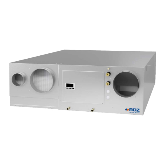
- Page 1 Air Handling Units Unità Trattamento Aria UC 360 V1 Residential Dehumidifier with MVHR System Deumidificatore Residenziale con Sistema VMC INSTALLATION / TECHNICAL MANUAL MANUALE INSTALLAZIONE / TECNICO...
- Page 3 Il suo utilizzo è raccomandato, entro i limiti di funzionamento, in ambienti civili e/o del applications and/or commercial ones (e.g. offices). Any other different use MUST be agreed in advance with RDZ settore terziario (uffici, ...), per climatizzazione finalizzata technical department.
- Page 4 SAFETY WARNINGS - AVVERTENZE PER LA SICUREZZA Read this manual carefully before installing and/or using the Le g g e re co n at te n z i o n e q u e s to l i b re t to p r i m a equipment and keep it in an accessible place.
- Page 5 SPECIFIC WARNINGS FOR AVVERTENZE SPECIFICHE APPLIANCE WITH PER APPARECCHIO CON GAS R290 REFRIGERANT GAS REFRIGERANTE R290 • Read the warnings carefully. • Leggere attentamente le avvertenze. • The appliance must be placed in an environment free of sources • L’apparecchio va posizionato in un ambiente privo di sorgenti of ignition in continuous operation (for example: open flames, di accensione in funzionamento continuo (per esempio: gas or electric appliances in operation).
- Page 6 INDEX - INDICE Description Descrizione GENERAL WARNINGS AVVERTENZE GENERALI SAFETY WARNINGS AVVERTENZE PER LA SICUREZZA DISPOSAL SMALTIMENTO PRELIMINARY OPERATIONS OPERAZIONI PRELIMINARI GENERAL OVERVIEW PANORAMICA GENERALE Description Descrizione Machine Components Componenti Apparecchiatura Package Content Contenuto Imballo Complements Complementi Unit circuit description Descrizione circuiti macchina Safety checks Controlli di sicurezza...
- Page 7 PRELIMINARY OPERATIONS - OPERAZIONI PRELIMINARI TESTING, TRANSPORT AND UNPACKAGING ISPEZIONE, TRASPORTO E DISIMBALLO Upon receipt, check immediately that the packaging is intact: All’atto del ricevimento verificare immediatamente l’integrità the machine has left the factory in perfect working order and any dell’imballo: la macchina ha lasciato la fabbrica in perfetto stato, damage must be notified to the carrier immediately and noted on eventuali danni dovranno essere immediatamente contestati...
- Page 8 Prevista per l’installazione orizzontale summer and winter sensible capacity. UC 360 V1 is designed for horizontal a soffitto, è dotata di circuito frigorifero completo (Refrigerante R290)
- Page 9 AIR FLOWS - FLUSSI ARIA Exhaust Air Fresh Air Inlet Supply Air Recirculation Air Stale Air Extraction Espulsione aria Ingresso Aria Esterna Estrazione aria viziata Immissione Aria Ricircolo Aria Ø coarse Ø coarse Ø Ø Ø Wiring Box Quadro Elettrico Ø...
- Page 10 SF-P Condensate drain kit with casing, designed for wall installation. It can be used in combination with RDZ air handling units, and it is suitable for Ø 20-32 mm piping. The external shell can be adjusted considering the thickness of the wall. Washable Internal Cartridge.
- Page 11 RICAMBI AIR FILTERS KIT - KIT FILTRI ARIA Cod. UC 360 V1 FILTER KIT Kit for complete replacement of unit filters containing: - 1 ISO Coarse 65% filter - Size 213x205x30 mm - 1 ISO Coarse 65% filter - dimensions 113x200x30 mm...
- Page 12 1.6 SAFETY CHECKS / CONTROLLI DI SICUREZZA All the control devices are tested in the factory before the equipment Tutti i dispositivi di controllo sono collaudati in fabbrica prima is shipped. Their operation is described in the following paragraphs. della spedizione dell’apparecchiatura. La loro funzionalità viene descritta nei paragrafi successivi.
-
Page 13: Installation - Installazione
INSTALLATION - INSTALLAZIONE AERAULIC SYSTEM RETE AERAULICA AIR FLOWS - FLUSSI ARIA Fresh Air Inlet Exhaust Air Stale Air Extraction Supply Air Recirculation Air Espulsione aria Ingresso Aria Esterna Estrazione aria viziata Immissione Aria Ricircolo Aria Ø Ø Ø Ø Ø... - Page 14 2.2 AERAULIC CONNECTIONS / COLLEGAMENTI AERAULICI Four Ø 160 mm diameter and one Ø 125 mm diameter sockets are Sono disponibili quattro bocchette di diametro Ø 160 mm e provided for connecting the ducting. Ductwork should be securely una bocchetta diametro Ø 125 mm per il collegamento delle connected to the sockets using acrylic sealant;...
- Page 15 Positioning indications & Minimum space allowanceses Indicazioni di posizionamento & Distanze minime di rispetto HORIZONTAL POSITIONING POSIZIONAMENTO ORIZZONTALE ≥ 60 cm Exhaust Espulsione Inlet Exhaust Immissione Espulsione ≥ 60 cm Inlet Immissione Exhaust Inlet INSIDE OUTSIDE Immissione Espulsione INTERNO ESTERNO VERTICAL POSITIONING POSIZIONAMENTO VERTICALE Inlet...
- Page 16 POSITIONING AND FIXING TO THE CEILING - POSIZIONAMENTO E FISSAGGIO A SOFFITTO CAUTION ATTENZIONE Installation and maintenance must be carried out by qualified L’installazione e la manutenzione vanno eseguiti solo personnel only. Throughout installation, make sure that the da personale qualificato. Durante tutte le procedure di equipment is not connected to the electrical mains.
- Page 17 ø8mm Rubber mounts Gommino antivibrante Washer Rondella Fixing to ceiling Fissaggio a so tto min. min. 15 cm 15 cm Opening Botolini Trap door Botola d’ispezione...
- Page 18 RDZ condensate drain kits (SF-P / SF-M 20). According esigenze, fra i kit di scarico condensa RDZ disponibili to the model chosen, respect the installation (SF-P / SF-M 20).
-
Page 19: Installation
SF-P Cod. Condensate drain kit with casing, designed for wall installation. It can be used in combination with RDZ air handling units, and it is suitable for Ø 20-32 mm piping. The external shell can be adjusted considering the thickness of the wall. Washable Internal Cartridge. For information see the dedicated technical sheet. - Page 20 RDZ air handling units. 3600400 Kit di scarico condensa composto da sifone con membrana in silicone, tubo e raccordo, da utilizzare in abbinamento alle unità di trattamento dell’aria RDZ. NOTE AGGIUNTIVE PER INSTALLAZIONE KIT SCARICO RDZ ADDITIONAL NOTES FOR RDZ DRAIN KIT INSTALLATION •...
-
Page 21: Hydraulic Connection
HYDRAULIC CONNECTION ALLACCIAMENTO IDRAULICO Hydraulic connection to a refrigerating unit capable L’allacciamento idraulico ad un gruppo frigo in grado of supplying chilled water is indispensable. In this case, the di fornire acqua refrigerata risulta indispensabile. dehumidifier can operate without varying the temperature of In tale caso il deumidificatore potrà... - Page 22 2.5 ELECTRICAL CONNECTIONS / COLLEGAMENTI ELETTRICI OVERVIEW OF THE ELECTRONIC BOARD UNIT PANORAMICA SCHEDA ELETTRONICA A BORDO Descriptions Descrizione Digital Outputs 6 and 7 Uscite Digitali 6 e 7 Digital Outputs 1... 5 Uscite Digitali 1... 5 Digital Output 9 Uscita Digitale 9 Display and Keyboard Visualizzatore e tastiera...
- Page 23 TERM. Meaning of connectors Significato dei connettori normally open contact digital output 6 contatto normalmente aperto uscita digitale 6 normally open contact digital output 7 contatto normalmente aperto uscita digitale 7 CO6/7 common digital outputs 6 and 7 comune uscite digitali 6 e 7 normally open contact digital output 1 contatto normalmente aperto uscita digitale 1 normally open contact digital output 2...
- Page 24 power supply 0-20 mA/4-20 mA/0-10 V transducers (12 VDC, alimentazione trasduttori 0-20 mA/4-20 mA/0-10 V (12 +12V 120 mA max.) VDC, 120 mA max.) power supply 0-5 V ratiometric transducers (5 VDC, 60 mA alimentazione trasduttori raziometrici 0-5 V (5 VDC, 60 max.) mA max.) common analog inputs and analog outputs...
- Page 25 TECHNICAL DATA OF THE ELECTRONIC BOARD UNIT DATI TECNICI SCHEDA ELETTRONICA A BORDO Index of protection: IP20; IP40 the front. Grado di protezione: IP20; IP40 il frontale. The maximum lengths of the connecting cables are the followings: Le lunghezze massime dei cavi di collegamento sono le •power supply controller: 100 m seguenti: •analog inputs: 100 m ;...
-
Page 26: Installation Instructions
INSTALLATION INSTRUCTIONS INDICAZIONI DI INSTALLAZIONE The dehumidifier must be connected to a disconnected, Il deumidificatore deve essere collegato ad una earthed power socket. The electrical system must be protected presa di corrente sezionata provvista di terra. L’impianto against overloads, short circuits and direct and indirect elettrico di alimentazione deve essere protetto contro i contacts and comply with the laws and regulations in force in sovraccarichi, i cortocircuiti, i contatti diretti ed indiretti,... -
Page 27: Power Supply
POWER SUPPLY ALIMENTAZIONE Connect the 3 terminals with tripolar 3x1.5mm² cable: Portare e collegare con cavo tripolare 3x1.5mm² i 3 morsetti: • Phase (L) • Fase (L) • Neutral (N) • Neutro (N) • Ground • Terra... -
Page 28: Digital Output
2.6 DIGITAL CONSENT / COMANDI DIGITALI SEASON STAGIONE RECIRCULATION RICIRCOLO RENEWAL RINNOVO DEHUMIDIFICATION DEUMIDIFICAZIONE INTEGRATION INTEGRAZIONE BOOST BOOST ECONOMY ECONOMY FILTERS ALARM ALLARME FILTRI GENERAL ALARM ALLARME GENERALE WATER PUMP POMPA ACQUA CAN - CAN + 0 Vac 24 Vac MODBUS GND MODBUS A/+ MODBUS B/-... -
Page 29: User Display
MODBUS A/+ USER DISPLAY TH MODBUS B/- MODBUS UC 360 V1 BOARD CONTROLLER UC 360 V1 - CONTROLLORE A BORDO WI UNIT CONTROLLER CENTRALINA “WI” serial card 1 PUSH micro-switch 2 (CAN LT) on position ON; SPINGERE il micro-switch 2 (CAN LT) in posizione ON. - Page 30 Very low flow rate values can cause malfunctioning Portate insufficienti causano malfunzionamenti in UC 360 V1 unit and they can activate relevant all’unità UC 360 V1 e l’attivazione di allarmi con alarms. In this case the unit stops working and shall blocco macchina a riarmo manuale.
- Page 31 3.2 PARAMETERS SETTING / SETTAGGIO PARAMETRI Essendo l’UC 360 V1 una macchina versatile e adattabile a Since UC 360 V1 unit is a versatile solution which can be suited to più situazioni, si rende necessario il settaggio dei parametri very different applications, the setting of the controller parameter della centralina in base alla conformazione dell’impianto, alle...
-
Page 32: Visual Signals
3.3 UNIT STARTING / ACCENSIONE MACCHINA Before switching on the unit, make sure that wiring Prima di accendere la macchina, assicurarsi che connection has been carried out in the right way. tutti i collegamenti elettrici siano stati realizzati in maniera corretta. VISUAL SIGNALS SEGNALAZIONI VISIVE Description of the controller LEDs - Descrizione Led del controllore... - Page 33 4 CONTROLLER ON BOARD - CONTROLLORE A BORDO 4.1 CONTROLLER DESCRIPTION / DESCRIZIONE CENTRALINA DISPLAY DISPLAY Through the controller display it is possible: Tramite il display del controllore è possibile: - View the active functionality at any time; - Visualizzare la funzionalità attiva in ogni momento; - View the status of the inputs and outputs;...
- Page 34 BUTTONS TASTI Buttons description / Descrizione tasti Description Descrizione Si ottiene l’uscita da menù, da elenco parametri, da valore Exit menus, list of parameters and parameter value (without parametro (senza salvataggio valore) e ritorno a livello saving the value) and go back to the previous level precedente •...
- Page 35 4.3 SET MENU / MENU SET In the set menu it is possible to: Nel menu set è possibile: • Set the operation in the current season • Impostare il funzionamento nella stagione corrente • Set the date and time of the device •...
-
Page 36: Impostazione Data-Ora
DATE-TIME SETTING IMPOSTAZIONE DATA-ORA Menu Home Descrizione Description Set the date and time of the device Settare la data e l’ora del dispositivo Through the operations listed below it is possible to set the date Attraverso le operazioni elencate successivamente è possibile and time of the device. -
Page 37: View Software Version
VIEW SOFTWARE VERSION VISUALIZZA VERSIONE SOFTWARE Menu Home Description Descrizione Displays the installed software version number Visualizza il numero di versione software installato Displays the installed software revision number Visualizza il numero di revisione software installato Displays A.T.U. model (push x 3) Visualizza il modello U.T.A. - Page 38 4.5 TECHNICAL MENU / MENU TECNICO To enter the Technical Menu, a password must be entered: Per accedere al Menu Tecnico è necessario l’inserimento di (default 11). una password (default 11) . Dopo aver inserito la password After entering the correct password, the relevant menu masks will corretta, verranno visualizzate le relative maschere del menu be displayed, indicated by the appearance of the icon.
- Page 39 AIR FLOW SETTINGS IMPOSTAZIONI PORTATE ARIA Menu Menu antc Home Modify - Modifica antc antc Description Descrizione Min Max Def. Supply Air Flow (m Portata Aria Immissione (m Dehumidification/Integration/ modalità Deumidificazione/Integrazione/ Recirculation mode Ricircolo Supply Air Flow (m Portata Aria Immissione (m Renewal mode modalità...
- Page 40 SETTINGS OF THE RECIRCULATION DAMPER S1 IMPOSTAZIONI SERRANDA DI RICIRCOLO S1 s-s1 Home Menu Menu antc Modify - Modifica s-s1 s-s1 antc antc Description Descrizione Def. Enable the pressure transducer Abilita il trasduttore di pressione enmp enmp Enable the damper test Abilita il Test della Serranda ents ents...
- Page 41 SETTINGS OF THE INTEGRATION PARAMETERS IMPOSTAZIONI DEI PARAMETRI DI INTEGRAZIONE Home Menu Menu antc Access to the mask antc antc Accesso alla maschera Description Descrizione Impostazioni per la Regolazione della Settings for Pre-Treatment Battery Adjustment Batteria di Pre-Trattamento Impostazione dei Parametri generali di Setting the General Integration Parameters Integrazione Menu...
- Page 42 SETTINGS OF THE DEFROSTING PARAMETERS IMPOSTAZIONI DEI PARAMETRI SBRINAMENTO sbri Menu Menu antc Home Modify - Modifica DEFR sbri antc antc Description Descrizione Def. Set the Defrosting Activation Temperature Imposta la Temperatura di Attivazione -10.0 +10.0 TDEF TSBR (° C) Sbrinamento (°C) Imposta il ritardo di Attivazione Set the Defrosting Activation delay (sec.)
- Page 43 SYNOPTIC MENU MENU SINOTTICO Menu Menu mNTC Home Modify - Modifica mNTC mNTC Description Descrizione Def. Enable Synoptic Controls (Manual) Abilita Comandi Sinottico (Manuale) AUTO MAN AUTO Abilita Uscita Analogica Enable Supply Fan Analog Output 10.0 Ventilatore Immissione Number of turns of the intake fan Numero di giri del ventilatore di Immissione Abilita Uscita Analogica Enable Expulsion Fan Analog Output...
- Page 44 SEASON CONTROL SELECTOR SELETTORE COMANDO STAGIONE Menu Menu antc Home Modify - Modifica Description Descrizione Def. Decidere se impostare la Stagione tramite Decide whether to set the Season via digital ingresso digitale (ID) o Interfaccia Utente input (ID) or User Interface (IU) (IU) TIPOLOGIA DI FUNZIONAMENTO INGRESSI TYPE OF OPERATION INPUTS...
- Page 45 AIR FILTER CONTROL PARAMETERS PARAMETRI DI CONTROLLO FILTRI ARIA Through this menu it is possible to enable / disable the unit air filter Tramite questo menu è possibile abilitare/disabilitare il control and set the verification parameters: controllo filtri aria dell’unità e impostare i parametri di verifica: •...
-
Page 46: Setting The Alarm Parameters
SETTING THE ALARM PARAMETERS IMPOSTAZIONE DEI PARAMETRI ALLARME stal Menu Menu antc Home Modify - Modifica stal stal mntc mntc Description Descrizione Def. Set maximum condensation temperature Imposta Temperatura massima di 45.0 65.0 55.0 tmc0 tmc0 (° C) condensazione (° C) Set H2O High Temperature Alarm Delay I m p o s t a R i t a r d o A l l a r m e A l t a dh20... -
Page 47: Alarms - Allarmi
RESET AND RESTORE FACTORY DATA RESET E RIPRISTINO DATI DI FABBRICA Perform this procedure to reset the remote control and return it to Eseguire questa procedura per resettare il controllo remoto e the factory status with the default values riportarlo allo stato di fabbrica con i valori di default Menu Menu antc... - Page 48 Display Alar AlLA Description Descrizione Antifreeze Alarm Allarme Antigelo - - - / YES High Temperature Condensation Alarm Allarme Alta Temperatura Condensazione - - - / YES HTMP HTMP Freon Gas Failure Alarm Allarme Mancanza Gas freon - - - / YES LOUG LOUG High Water Temperature Alarm...
- Page 49 Do not connect directly extractor hood and UC 360 V1 Evitare nel modo più assoluto il collegamento diretto tra cappa aspirante e UC 360 V1...
- Page 50 UNIT FUNCTION TABLE TABELLE FUNZIONAMENTI MACCHINA Truth table about hydraulic/refrigerating mode Tabella di verità delle funzionalità idraulico/frigorifere Input settings Components Impostazioni di input Componenti Pump consent Season Dehumidification Integration Compressor Valvola Valvola Pre Comando Stagione Deumidifica Integrazione Compressore Integrazione pompa All open All open Tutta aperta...
- Page 51 Advanced functionings table Tabella funzionamenti avanzati COMBINED FUNCTIONING SEASON S3 FC FUNZIONAMENTO COMBINATO STAGIONE RENEWAL SUM / EST RINNOVO WIN / INV DEHUMIDIFICATION SUMMER DEUMIDIFICAZIONE ESTATE SUMMER ESTATE RECIRCULATION INTEGRATION RICIRCOLO INTEGRAZIONE WINTER INVERNO SUM / EST BOOST WIN / INV SUM / EST FREE-COOLING WIN / INV...
- Page 52 6.2 FLOW RATE DIAGRAM / SCHEMI GRAFICI GESTIONE PORTATE ARIA AIR FLOWS - FLUSSI ARIA Fresh Air Inlet Exhaust Air Supply Air Recirculation Air Stale Air Extraction Ingresso Aria Esterna Espulsione aria Estrazione aria viziata Immissione Aria Ricircolo Aria MVHR Heat exchanger Recuperatore di calore Feature...
- Page 53 FREE COOLING FREE COOLING Finned pack Heat exchanger Pacco alettato Recuperatore di calore Feature Value Funzionalità Valore % setting to the range Impostazione % su range Free-Cooling Free-Cooling (0% = 100 m /h, 100% = 240 m (0% = 100 m /h, 100% =240 m AIR HANDLING + FRESH AIR VENTILATION CONDIZIONAMENTO + RINNOVO...
- Page 54 6.3 COMPONENTS DIAGRAM / SCHEMI GRAFICI GESTIONE COMPONENTI AIR FLOWS - FLUSSI ARIA Fresh Air Inlet Exhaust Air Stale Air Extraction Supply Air Recirculation Air Espulsione aria Ingresso Aria Esterna Estrazione aria viziata Immissione Aria Ricircolo Aria Legend of components Legenda dei componenti Rif.
-
Page 55: Fresh Air Ventilation
FRESH AIR VENTILATION RINNOVO Rif. Descriptions Descrizione Rif. Descriptions Descrizione S1 - Recirculation damper S1 - Serranda Ricircolo Inflow fan Ventilatore immissione S2 - Extract damper Exhaust fan S2 - Serranda Estrazione Ventilatore espulsione S3 - Serranda Free Cooling OFF S3 - Free Cooling damper Compressor Compressore... - Page 56 DEHUMIDIFICATION / SUMMER INTEGRATION DEUMIDIFICAZIONE / INTEGRAZIONE ESTIVA Rif. Descriptions Descrizione Rif. Descriptions Descrizione S1 - Recirculation damper S1 - Serranda Ricircolo Inflow fan Ventilatore immissione S2 - Extract damper S2 - Serranda Estrazione Exhaust fan Ventilatore espulsione S3 - Serranda Free Cooling OFF S3 - Free Cooling damper Compressor Compressore...
- Page 57 WINTER INTEGRATION INTEGRAZIONE INVERNALE Rif. Descriptions Descrizione Rif. Descriptions Descrizione S1 - Recirculation damper S1 - Serranda Ricircolo Inflow fan Ventilatore immissione S2 - Extract damper S2 - Serranda Estrazione Exhaust fan Ventilatore espulsione S3 - Serranda Free Cooling OFF S3 - Free Cooling damper Compressor Compressore...
-
Page 58: Maintenance - Manutenzione
È consentito pulire i filtri a vapore. After 3 consecutive cleaning operations, filter must be replaced. Dopo un ciclo di 3 pulizie consecutive il filtro deve essere Contact RDZ to purchase new filters. sostituito. Contattare RDZ per l’acquisto di nuovi filtri. OFF! every 90 days Spento! -
Page 59: Cleaning The Exchanger
CLEANING THE EXCHANGER PULIZIA SCAMBIATORE Warning: the heat exchanger have to be cleaned every 2 years by Attenzione! La pulizia dello scambiatore di calore va effettuata removing the bottom panel from the dehumidifier. ogni 2 anni e avviene rimuovendo il pannello inferiore del deumifìdificatore. -
Page 60: Removing The Fan
7.2 EXTRAORDINARY MAINTENANCE / MANUTENZIONE STRAORDINARIA REMOVING THE FAN RIMOZIONE VENTILATORE Caution! To replace the fan you must remove the lower dehumidifier Attenzione! La sostituzione del ventilatore avviene rimuovendo panel. il pannello inferiore del deumidificatore. In order to replace the electric fan condenser (at the side of the motor), it is not necessary to remove the fan. - Page 61 8 TECHNICAL DATA AND PERFORMANCE - DATI TECNICI E PRESTAZIONI 8.1 DIMENSIONS AND TECHNICAL DATA / DIMENSIONI E DATI TECNICI 1202 1282 [mm] AIR FLOWS - FLUSSI ARIA Fresh Air Inlet Exhaust Air Recirculation Air Stale Air Extraction Supply Air Espulsione aria Ingresso Aria Esterna Estrazione aria viziata...
- Page 62 8.2 OPERATING LIMITS / LIMITI DI FUNZIONAMENTO The graphs shown below describe the operating range of the unit. I grafici sottoriportati descrivono il campo operativo dell’unità. La The maximum permitted temperature of the water for operation massima temperatura dell’acqua ammessa nel funzionamento in summer mode is 18 °C.
- Page 63 8.3 OPERATION IN VENTILATION MODE ONLY / FUNZIONAMENTO IN SOLA VENTILAZIONE If the unit is requested to run the renewal or boost function, it is Nel caso in cui all’unità venga richiesta la funzione di rinnovo necessary to provide the machine using a certain amount of power o boost, si rende necessario dover fornire alla macchina una from the hydronic circuit to make the neutral air exit the unit.
- Page 64 8.4 SUMMER PERFORMANCE / PRESTAZIONI ESTIVE Yield during dehumidification, depending on room temperature, Resa in deumidificazione, in funzione della temperatura relative humidity, considering a unit supplied with water at 15°C. ambiente, umidità relativa considerando l’unità alimentata con acqua a 15°C. Performance in recirculation mode Resa in ricircolo Sens.
- Page 65 Performance in recirculation mode + renewal mode Resa in ricircolo + rinnovo Sens. cooling Neutral outlet Latent cooling Cooling power to be power Renewal air Recirculation air power supplied to the unit Pot. frig. Potenza frigorifera sensibile Aria di rinnovo Aria di ricircolo Aria neutra in Pot.
- Page 66 EXAMPLE OF RECIRCULATION PERFORMANCE ESEMPIO PRESTAZIONE RICIRCOLO Yield during dehumidification in recirculation mode, with a flow Resa in deumidificazione in modalità ricircolo con portata di 360 rate of 360 m /h, with a unit supplied with water at a temperature /h, unità...
- Page 67 EXAMPLE OF RENEWAL PERFORMANCE ESEMPIO PRESTAZIONE RINNOVO Yield during dehumidification in renewal mode, with a flow rate Resa in deumidificazione in modalità rinnovo con portata di of 240 m /h, with a unit supplied with water at a temperature of 240 m /h, unità...
- Page 68 EXAMPLE OF RECIRCULATION + RENEWAL PERFORMANCE ESEMPIO PRESTAZIONE RICIRCOLO + RINNOVO Yield during dehumidification in recirculation + renewal mode Resa in deumidificazione in modalità ricircolo + rinnovo con with a total flow rate of 360 m /h, when the unit is supplied with portata totale di 360 m /h, unità...
- Page 69 8.5 OPERATION IN WINTER INTEGRATION MODE / FUNZIONAMENTO INTEGRAZIONE INVERNALE If the winter integration function is enabled, the unit will start the Se viene attivata la funzione di integrazione invernale, l’unità delivery fan (if renewal is enabled then the output fan will also attiva il ventilatore di immissione (in caso di rinnovo anche il start).
- Page 70 8.6 RECOVERY UNIT PERFORMANCE / PRESTAZIONI RECUPERATORE EFFICIENCY EFFICIENZA Renewal air ow rate [m /h] Portata aria rinnovo [m /h]...
- Page 71 8.7 PRESSURE LOSS OF THE HYDRAULIC CIRCUIT / PERDITA DI CARICO CIRCUITO IDRAULICO 24,1 20,1 UC + owmeter UC + misu. di portata Water ow rate [l/h] Portata acqua [l/h]...
- Page 72 9 WIRING DIAGRAM - SCHEMA ELETTRICO COLOR TABLE BIANCO TABELLA COLORI BIANCO GRIGIO VIOLET - VIOLA NERO BLACK - NERO UC 360 V1 BIANCO PINK - ROSA GRIGIO ROSSO ORANGE - ARANCIO REV. 02 BIANCO CAN + WHITE - BIANCO...
- Page 73 BIANCO [Vout] TRANSDUCER VIOLA [24V] TRASDUTTORE BIANCO NERO PRESSURE TRANSDUCER / V TRASDUTTORE PRESSIONE [GND] GIALLO-IMMISSIONE 0-10V SUPPLY FAN / 0-10V VENTILATORE IMMISSIONE GIALLO-ESPULSIONE 0-10V EXHAUST FAN / 0-10V VENTILATORE ESPULSIONE NERO+NERO SUPPLY FAN GND FANS / GND VENTILATORI VENTILATORE IMMISSIONE GRIGIO-IMMISSIONE TACHOMETER SUPPLY FAN / TACHIMETRO VENTIL.
- Page 76 FAG0CA034AB.06 02/2022...
Need help?
Do you have a question about the UC 360 V1 and is the answer not in the manual?
Questions and answers