
Subscribe to Our Youtube Channel
Related Manuals for RDZ UC 500-MHE


Summary of Contents for RDZ UC 500-MHE
- Page 1 Air Handling Units Unit Comfort UC 500-MHE Residential Dehumidifier with VMC System TECHNICAL / INSTALLATION MANUAL...
-
Page 3: Table Of Contents
DUCTABLE AIR HANDLING UNIT FOR FRESH AIR VENTILATION AND HEAT RECOVERY mod. UC 500-MHE SUMMARY TRANSPORT AND STORAGE 2 DESCRIPTION OF THE MACHINE AND USE 2 DESCRIPTION OF OPERATIONS 3 DIMENSIONS 5 INSTALLATION 6 CONNECTIONS 8 START-UP AND COMMISSIONING 11 ... -
Page 4: Transport And Storage
CONTENTS OF THE PACKAGING The UC 500-MHE unit is packed onto a wooden pallet, and protected by a cardboard box. The packaging contains: 1 UC 500-MHE unit; 1 use and maintenance manual. Size of the packaging: 98x137x 53(h) cm;... -
Page 5: Description Of Operations
UC 500-MHE – INSTALLATION, USE AND MAINTENANCE MANUAL DESCRIPTION OF OPERATIONS The following figure shows the machine layout, the main components and the air flows. OUTDOOR INDOOR 1 – Air to air heat exchanger 2 - Cooling compressor; 3 - Water finned coil;... - Page 6 The following types of air handling can be carried out: fresh air ventilation with high efficiency heat recovery, with possible winter heating or summer cooling; fresh air ventilation with free-cooling, that is without heat recovery, both in summer and in winter;...
-
Page 7: Dimensions
UC 500-MHE – INSTALLATION, USE AND MAINTENANCE MANUAL DEHUMIDIFICATION AND COOLING The finned coil (3) supplied with the water coming from the radiant system, cools down the air, while the cooling evaporator (4) performs further cooling and dehumidification. The refrigeration circuit is made up of two condensers connected in parallel: in addition to the an air-cooled condenser (5) a second condenser is cooled by the outgoing air flow (6), thus releasing the condensation heat outwards. -
Page 8: Installation
INSTALLATION SAFETY WARNINGS Installation and maintenance must be carried out only by qualified personnel. The machine must be protected from frost. Hydraulic and electrical systems, along with the installation position, must comply with the safety rules and regulations in force in the country where the unit has been installed. Read the instructions in this manual carefully before working on the machine. - Page 9 UC 500-MHE – INSTALLATION, USE AND MAINTENANCE MANUAL Positioning The machine must be installed inside buildings, positioned horizontally. Operation in an inclined position of more than 1% may cause water leakage or may damage internal devices. DOWN Minimum distances for installation...
-
Page 10: Connections
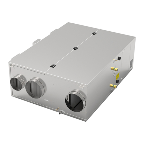
CONNECTIONS KEY TO SYMBOLS 1 - cold/hot water input; 7 - summer condensate drain; 2 - cold/hot water output; 8 - stale air exhaust; 3 - electrical input connections; 9 - outdoor air intake; 4 - hydraulic circuit vent; 10 - stale air extract; 5 - dehumidifier condensate drain;... - Page 11 UC 500-MHE – INSTALLATION, USE AND MAINTENANCE MANUAL Aeraulic connections The machine is equipped with metal spigots, which protrude about 4 cm and which make it possible the connection with flexible or rigid ducts, provided that they are equipped with gaskets to avoid air leaks and unpleasant noise.
- Page 12 TECHNICAL DATA Power supply V/Ph/Hz 230 - 1 - 50 Weight l/24h 74.1 Total dehumidification capacity (Outdoor temperature 35°C, 50% R.H.) 2090 l/24h 31.2 Useful dehumidification capacity (referring to recirculation, room temperature at 26°C, 55% R.H.) Useful cooling capacity (referred to recirculation, 2580 room temperature at 26°C, 55% R.H.) Maximum electrical power use of compressor...
-
Page 13: Start-Up And Commissioning
Machines equipped with a Control Panel can also read the levels of the temperature sensors which the machine is equipped with. These values can be useful in the testing phase or while verifying the correct operation. Further details can be found in the manual: “UC 500-MHE Control Panel”. 11 ... - Page 14 SUMMER OPERATING MODE FRESH AIR VENTILATION Both fans are running and carrying fresh ventilation: the outdoor air is cooled down by the heat exchanger using exhaust air first, and then by OUTDOOR INDOOR refrigerated water circulating in the finned coil. AIR DEHUMIDIFICATION The compressor and the supply fan are running;...
- Page 15 UC 500-MHE – INSTALLATION, USE AND MAINTENANCE MANUAL HEAT RECOVERY BYPASS Both fans are running, the intake air damper is closed and the bypass damper is open. The inflow air is warmed up by the water coil. The air flow rate can be set...
- Page 16 FRESH AIR VENTILATION + AIR RECIRCULATION The fans are both running. The supply air is warmed up by the water coil. The intake air is pre-heated by the heat exchanger using exhaust air. The supply air flow rate can be set from 300 to 500 m³/h, while the flow rate...
-
Page 17: Routine Maintenance
UC 500-MHE – INSTALLATION, USE AND MAINTENANCE MANUAL ROUTINE MAINTENANCE Routine maintenance involves the cleaning of the air filters. The filters should be checked every 90 days. To remove and clean the filters: unscrew the knobs that fix the filter cover, near the air spigots;... -
Page 18: Warnings For The Correct Disposal Of The Product
WARNINGS FOR THE CORRECT DISPOSAL OF THE PRODUCT According to the provisions of the following European directives 2011/65/EU, 2012/19/EU, and 2003/108/CE, concerning the restriction of the use of certain hazardous substances in electrical and electronic equipment, as well as waste disposal. The crossed out wheelie bins symbol on the equipment indicates that, at the end of its useful life, the product must be collected separately from general waste. - Page 20 FAG0CA031BZ.01 09/2019...
Need help?
Do you have a question about the UC 500-MHE and is the answer not in the manual?
Questions and answers