
Related Manuals for RDZ UAP 201-PDC


Summary of Contents for RDZ UAP 201-PDC
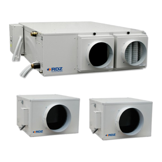
- Page 1 Air Handling Units Unità Trattamento Aria UAP 201-PDC Residential Dehumidifier with VMC System Deumidificatore Residenziale con Sistema VMC TECHNICAL / INSTALLATION MANUAL MANUALE TECNICO / INSTALLAZIONE...
-
Page 3: Avvertenze Per La Sicurezza
SAFETY WARNINGS - AVVERTENZE PER LA SICUREZZA Read this manual carefully before installing and/or using the Le g g e re co n at te n z i o n e q u e s to l i b re t to p r i m a equipment and keep it in an accessible place. -
Page 4: Avvertenze Generali
GENERAL WARNINGS - AVVERTENZE GENERALI • If, after having unpacked the equipment, any anomaly is noted, • Se dopo aver disimballato l’apparecchiatura si nota una do not use the equipment and contact an Assistance Centre qualsiasi anomalia non utilizzare l’apparecchiatura e rivolgersi authorised by the manufacturer. -
Page 5: Table Of Contents
INDEX - INDICE Description Descrizione SAFETY WARNINGS AVVERTENZE PER LA SICUREZZA GENERAL WARNINGS AVVERTENZE GENERALI DISPOSAL SMALTIMENTO PRELIMINARY OPERATIONS OPERAZIONI PRELIMINARI GENERAL OVERVIEW PANORAMICA GENERALE Description Descrizione Unit circuits description Descrizione circuiti macchina Unit circuits diagram Schema circuiti macchina Unit components list Elenco componenti macchina INSTALLATION INSTALLAZIONE... -
Page 6: Operazioni Preliminari
PRELIMINARY OPERATIONS - OPERAZIONI PRELIMINARI TESTING, TRANSPORT AND UNPACKAGING ISPEZIONE, TRASPORTO E DISIMBALLO Upon receipt, check immediately that the packaging is intact: All’atto del ricevimento verificare immediatamente l’integrità the machine has left the factory in perfect working order and any dell’imballo: la macchina ha lasciato la fabbrica in perfetto stato, damage must be notified to the carrier immediately and noted on eventuali danni dovranno essere immediatamente contestati... -
Page 7: Panoramica Generale
GENERAL OVERVIEW - PANORAMICA GENERALE DESCRIPTION - DESCRIZIONE Primary air unit for fresh air ventilation with high efficiency heat recovery Unità di aria primaria per il rinnovo dell’aria ambiente con (~90%), and for summer dehumidification with integration for additional recupero di calore ad alta efficienza (~90%) e per il trattamento sensible heating and cooling (operating as a heat pump). -
Page 8: Descrizione Circuiti Macchina
UNIT CIRCUITS DESCRIPTION - DESCRIZIONE CIRCUITI MACCHINA Rif. Descriptions Descrizione Inflow fan Ventilatore immissione Exhaust fan Ventilatore espulsione Heat recover unit Recuperatore di calore 2-way modulating valve 2 vie opzionale A Pre-treatment coil A Batteria pre-trattamento Batteria evaporante Evaporation coil Finned pack Pacco alettato (Batteria condensante in funzionamento... -
Page 9: Schema Circuiti Macchina
UNIT CIRCUITS DIAGRAM - SCHEMA CIRCUITI MACCHINA CO2-EV2 EV1-CO3 Rif. Descriptions Descrizione 2-way valve for water flow modulation on the Valvola 2 vie per la modulazione della portata d’acqua sulla pre-treatment coil batteria di pre-trattamento Pre-treatment coil Batteria di pre-trattamento Tube-in-tube for the pre-cooling of the out-coming gas Tubo in tubo, per pre-raffreddare il gas in uscita al condensatore to the condenser... -
Page 10: Elenco Componenti Macchina
UNIT COMPONENTS LIST - ELENCO COMPONENTI MACCHINA Components Description Componente Descrizione Compressor Sealed Compressore Di tipo ermetico Ph a s e c l a m p 250V- 8 A Fusibile 250V- 8 A fuse morsetto fase Heat exchanger High efficiency cross-flow exchanger Scambiatore di Scambiatore ad alta efficienza (circa 90%) a (approximately 90%). -
Page 11: Installazione
INSTALLATION - INSTALLAZIONE APPLICATION EXAMPLE / ESEMPIO APPLICATIVO... -
Page 12: Rete Aeraulica
AERAULIC SYSTEM RETE AERAULICA INSTALLATION INSTRUCTIONS INDICAZIONI DI INSTALLAZIONE Four Ø 150 mm diameter sockets are provided for connecting the Sono disponibili quattro bocchette di diametro Ø 150 mm per il ducting. Ductwork should be securely connected to the sockets collegamento delle tubazioni. - Page 13 Inlet fresh air from outside / Presa Aria fresca dall’esterno Extract stale air from rooms / Ripresa aria viziata dalle stanze Supply fresh air to rooms / Immissione aria in ambiente Exhaust stale air to outside / Espulsione aria viziata verso l’esterno Inlet fresh air from outside Supply fresh air to rooms Presa Aria fresca dall’esterno...
- Page 14 Positioning indications & Minimum space allowanceses Indicazioni di posizionamento & Distanze minime di rispetto HORIZONTAL POSITIONING POSIZIONAMENTO ORIZZONTALE ≥ 60 cm Exhaust Espulsione Inlet Exhaust Immissione Espulsione ≥ 60 cm Inlet Immissione Exhaust Inlet INSIDE OUTSIDE Immissione Espulsione INTERNO ESTERNO VERTICAL POSITIONING POSIZIONAMENTO VERTICALE Inlet...
-
Page 15: Posizionamento E Fissaggio Dell'unità
UNIT POSITIONING AND FIXING POSIZIONAMENTO E FISSAGGIO DELL’ UNITA’ ATTENZIONE CAUTION L’installazione e la manutenzione vanno eseguiti solo Installation and maintenance must be carried out by qualified da personale qualificato. Durante tutte le procedure di personnel only. Throughout installation, make sure that the installazione, assicurarsi che l’apparecchiatura non sia equipment is not connected to the electrical mains. - Page 16 ø7mm Rubber mounts Gommino antivibrante Washer Rondella Fixing to ceiling Fissaggio a so tto min. min. 60 cm 10 cm Opening Botolini Trap door Botola d’ispezione...
-
Page 17: Installazione Ventilatori
VENTILATORS INSTALLATION INSTALLAZIONE VENTILATORI RECOMANDED INSTALLATION INSTALLAZIONE CONSIGLIATA Inlet fresh air from outside Extract stale air from rooms Presa Aria fresca dall’esterno Ripresa aria viziata dalle stanze Exhaust stale air to outside Supply fresh air to rooms Immissione aria in ambiente Espulsione aria viziata verso l’esterno IMPROPER INSTALLATION INSTALLAZIONI DA EVITARE... - Page 18 ø7mm Rubber mounts Gommino antivibrante Fixing to ceiling Washer Fissaggio a so tto Rondella min. 10 cm min. 10 cm Trap door Botola d’ispezione...
-
Page 19: Collegamenti Idraulici
HYDRAULIC CONNECTIONS - COLLEGAMENTI IDRAULICI Rif. Description Descrizione Pre-treatment water outlet (1/2”F) with cut-off valve to Uscita acqua pre-trattamento (1/2”F) con valvola di intercettazione adjust flow rate per regolazione portata Pre-treatment water inlet (1/2”F) with lockshield to adjust Ingresso acqua pre-trattamento (1/2”F) con detentore di flow rate regolazione portata Si consiglia di installare i relativi misuratori di portata per il... - Page 20 SIFOWALL Condensate drain kit with casing, designed for wall installation. It can be used in combination with RDZ air handling units, and it is suitable for Ø 20-32 mm piping. The external shell can be adjusted considering the thickness of the wall. Washable Internal Cartridge. For information see the dedicated technical sheet.
- Page 21 RDZ air handling units. 3600401 Kit di scarico condensa composto da sifone con membrana in silicone, tubo e raccordo, da utilizzare in abbinamento alle unità di trattamento dell’aria RDZ. ADDITIONAL NOTES FOR RDZ DRAIN KIT INSTALLATION NOTE AGGIUNTIVE PER INSTALLAZIONE KIT SCARICO RDZ •...
- Page 22 HYDRAULIC CONNECTION ALLACCIAMENTO IDRAULICO Hydraulic connection to a refrigerating unit capable L’allacciamento idraulico ad un gruppo frigo in grado of supplying chilled water is indispensable. In this case, the di fornire acqua refrigerata risulta indispensabile. dehumidifier can operate without varying the temperature of In tale caso il deumidificatore potrà...
-
Page 23: Collegamenti Elettrici
ELECTRICAL CONNECTIONS / COLLEGAMENTI ELETTRICI OVERVIEW OF THE ON BOARD CONTROLLER PANORAMICA CONTROLLORE A BORDO Descriptions Descrizione Digital Outputs 6 and 7 Uscite Digitali 6 e 7 Digital Outputs 1... 5 Uscite Digitali 1... 5 Display and Keyboard Visualizzatore e tastiera Analog inputs, Digital inputs and Analog outputs Ingressi analogici, Ingressi digitali e Uscite Analogiche USB OTG port... - Page 24 TERM. Meaning of connectors Significato dei connettori normally open contact digital output 6 contatto normalmente aperto uscita digitale 6 normally open contact digital output 7 contatto normalmente aperto uscita digitale 7 CO6/7 common digital outputs 6 and 7 comune uscite digitali 6 e 7 normally open contact digital output 1 contatto normalmente aperto uscita digitale 1 normally open contact digital output 2...
- Page 25 INSTALLATION INSTRUCTIONS INDICAZIONI DI INSTALLAZIONE The dehumidifier must be connected to a disconnected, Il deumidificatore deve essere collegato ad una earthed power socket. The electrical system must be protected presa di corrente sezionata provvista di terra. L’impianto against overloads, short circuits and direct and indirect elettrico di alimentazione deve essere protetto contro i contacts and comply with the laws and regulations in force in sovraccarichi, i cortocircuiti, i contatti diretti ed indiretti,...
- Page 26 POWER SUPPLY ALIMENTAZIONE Connect the 3 terminals with 3x1.5mm cable: Portare e collegare con cavo 3x1.5mm i 3 morsetti: phase (F), neutral (N), earth fase (F), neutro (N) e terra The terminal of the tension line is provided with 8 A Il morsetto di linea dell’alimentazione elettrica è...
-
Page 27: Comandi Digitali
DIGITAL COMMANDS / COMANDI DIGITALI DIGITAL INPUT DIGITAL OUTPUT USCITE DIGITALI INGRESSI DIGITALI (mav 2A) BOOST WATER PUMP CONSENT FREECOOLING COMANDO POMPA ° C ACQUA SUMMER ESTATE ALARM ALLARME VENTILATION RINNOVO INTEGRATION INTEGRAZIONE ° C DEHUMIDIFICATION DEUMIDIFICAZIONE... -
Page 28: Collegamento Alle Centraline Di Comando
CONTROL UNIT / CENTRALINE DI COMANDO USER DISPLAY / USER DISPLAY TH WI-SA UAP 201 BOARD CONTROLLER DISPLAY RS485 UAP 201 - CONTROLLORE A BORDO PUSH micro-switch 2 (CAN LT) on position ON; SPINGERE il micro-switch 2 (CAN LT) in posizione ON. USER DISPLAY Micro-switch Connector 1... -
Page 29: Avviamento E Collaudo
(240 l/h) Very low flow rate values can cause malfunctioning Portate insufficienti causano malfunzionamenti in UAP 201-PDC unit and they can activate relevant all’unità UAP 201-PDC e l’attivazione di allarmi con alarms. In this case the unit stops working and shall blocco macchina a riarmo manuale. -
Page 30: Funzionamento
Do not connect directly extractor hood and UAP Evitare nel modo più assoluto il collegamento diretto tra cappa aspirante e UAP 201-PDC 201-PDC... -
Page 31: Schemi Grafici Gestione Portate Aria
FLOW RATE DIAGRAM / SCHEMI GRAFICI GESTIONE PORTATE ARIA MVHR Inlet fresh air from outside Extract stale air from rooms Presa Aria fresca Ripresa aria viziata dall’esterno dalle stanze Supply fresh air to rooms Immissione aria in ambiente Exhaust stale air to outside Espulsione aria viziata verso l’esterno Feature... -
Page 32: Schemi Grafici Gestione Componenti
COMPONENTS DIAGRAM / SCHEMI GRAFICI GESTIONE COMPONENTI FRESH AIR VENTILATION RINNOVO Rif. Descriptions Descrizione Status Rif. Descriptions Descrizione Status Inflow fan Ventilatore immissione 4-way valve Valvola 4 vie Exhaust fan Ventilatore espulsione 2-way valve Valvola 2 vie Free-cooling damper Servomotore serranda Pump Request Chiamata Pompa actuator... - Page 33 WINTER INTEGRATION INTEGRAZIONE INVERNALE Rif. Descriptions Descrizione Status Rif. Descriptions Descrizione Status Inflow fan Ventilatore immissione 4-way valve Valvola 4 vie Exhaust fan Ventilatore espulsione 2-way valve Valvola 2 vie Free-cooling damper Servomotore serranda Pump Request Chiamata Pompa actuator free-cooling Compressor Compressore FREE-COOLING / FREE-HEATING...
-
Page 34: Controllore A Bordo
CONTROLLER ON BOARD - CONTROLLORE A BORDO CONTROLLER DESCRIPTION / DESCRIZIONE CENTRALINA DISPLAY DISPLAY By using the controller screen it is possible: Tramite il display del controllore è possibile: - To change the parameter; - Effettuare la modifica dei parametri; - To read the status of inlets and outlets at any moment;... -
Page 35: Riepilogo Generale Dei Menu
BUTTONS TASTI Buttons description Descrizione tasti Button Description Descrizione Tasto Si ottiene l’uscita da menù, da elenco parametri, da valore Exit menus, list of parameters and parameter value (without parametro (senza salvataggio valore) e ritorno a livello saving the value) and go back to the previous level precedente •... - Page 36 READOUT LETTURE Param. Description Param. Descrizione Cond Cond Condensing temperature Temperatura di condensazione Evap Evap Evaporation temperature Temperatura di evaporazione Post Post Post-heating temperature (not used) Temperatura post-riscaldo (non usata) tH2O tH2O Inlet water temperature Temperatura acqua in ingresso Exte Este External temperature Temperatura esterna...
- Page 37 FAULTS GUASTI Param. Description Param. Descrizione Def. 5.1 Code Code System faults code Codice guasti macchina 5.2 Canc Alarms manual reset Canc Reset manuale allarmi Alarm Description Descrizione Allarme No fault Nessun guasto Guasto presente: verificare nella maschera letture il tipo Fault: check the failed probe type on the reading mask di sonda guasta TECHNICAL MENU FOLDER...
-
Page 38: Schema Menu Principale
MAIN MENU DIAGRAM / SCHEMA MENU PRINCIPALE... -
Page 39: Lista Parametri Menu Tecnico
TECHNICAL MENU PARAMETER LIST / LISTA PARAMETRI MENU TECNICO Param. Description Descrizione Def. Isteresi temperatura estiva: intervallo Summer temperature hysteresis: temperature di temperatura sopra e sotto il Set di 10.0 range above and below the activation settings and Po01 attivazione e interruzione richiesta interruption of the integration request integrazione Isteresi umidità... - Page 40 -25.0 -20.0 Po50 Minimum evaporation temperature Temperatura minima di evaporazione Tempo di By Pass allarme bassa 1200 Po51 Low temperature evaporation alarm bypass time temperatura di evaporazione Maximum condensing temperature Temperatura massima di condensazione 50.0 65.0 60.0 Po52 Temperature limit below which there is the risk of Temperatura limite sotto la quale c’è...
-
Page 41: Manutenzione
MAINTENANCE - MANUTENZIONE All the extraordinary maintenance operations Tutte le operazioni di manutenzione straordinaria described in this chapter MUST ALWAYS BE CARRIED OUT BY descritte in questo capitolo DEVONO ESSERE SEMPRE QUALIFIED PERSONNEL. ESEGUITE DA PERSONALE QUALIFICATO. • Before performing any intervention on the unit or before •... - Page 42 CLEANING THE EXCHANGER PULIZIA SCAMBIATORE Warning: the heat exchanger have to be cleaned every 2 years by Attenzione! La pulizia dello scambiatore di calore va effettuata removing the bottom panel from the dehumidifier. ogni 2 anni e avviene rimuovendo il pannello inferiore del deumifìdificatore.
-
Page 43: Manutenzione Straordinaria
EXTRAORDINARY MAINTENANCE / MANUTENZIONE STRAORDINARIA REMOVING THE FAN RIMOZIONE VENTILATORE Caution! To replace the fan you must remove the lower dehumidifier Attenzione! La sostituzione del ventilatore avviene rimuovendo panel. il pannello inferiore del deumifìdificatore. In order to replace the electric fan condenser (at the side of the motor), it is not necessary to remove the fan. -
Page 44: Dati Tecnici E Prestazioni
TECHNICAL DATA AND PERFORMANCE - DATI TECNICI E PRESTAZIONI DIMENSIONS / DIMENSIONI [mm] 1118 FAN DIMENSIONS DIMENSIONI VENTILATORI [mm]... -
Page 45: Dati Tecnici
TECHNICAL DATA / DATI TECNICI Table of technical characteristics Tabella delle caratteristiche tecniche Technical specifications Specifiche tecniche l/day Condensation (35°C - 50% - 200 m3/h) Umidità condensata (35°C - 50% - 200 m3/h) 38.7 l/giorno Rated electrical power Potenza elettrica nominale Total max. -
Page 46: Limiti Di Funzionamento
OPERATING LIMITS / LIMITI DI FUNZIONAMENTO The graphs shown below describe the operating range of the unit. I grafici sottoriportati descrivono il campo operativo dell’unità. La The maximum permitted temperature of the water for operation massima temperatura dell’acqua ammessa nel funzionamento in summer mode is 18 °C. - Page 47 EXAMPLE OF RENEWAL PERFORMANCE ESEMPIO PRESTAZIONE RINNOVO Yield during dehumidification in renewal mode, with a flow rate Resa in deumidificazione in modalità rinnovo con portata di of 150 m /h, with a unit supplied with water at a temperature of 150 m /h, unità...
- Page 48 RECOVERY UNIT PERFORMANCE PRESTAZIONI RECUPERATORE The heat recovery unit is of high efficiency type (~90%). The Il recuperatore di calore dell’unità è del tipo ad alta efficienza performance, however, must not be considered fixed. It can vary ~90%. Le prestazioni però, non sono da considerarsi fisse, according to various factors: air flow rate, outdoor temperature and possono variare secondo diversi fattori: portate dell’aria, relative humidity (the last two factors only apply to winter mode).
- Page 49 External temperature 0 °C Temperatura esterna 0 °C Room H.R. U.R. ambiente DRY / < 32% Renewal air ow rate [m /h] Portata aria rinnovo [m /h] External temperature -5 °C Temperatura esterna -5 °C Room H.R. U.R. ambiente DRY / < 25% Renewal air ow rate [m /h] Portata aria rinnovo [m /h]...
- Page 50 External temperature -10 °C Temperatura esterna -10 °C Room H.R. U.R. ambiente DRY / < 18% Renewal air ow rate [m /h] Portata aria rinnovo [m /h] Room R.H. U.R. ambiente Renewal air ow rate 80 m /h Portata aria rinnovo 80 m /h External temperature [°C] Temperatura esterna [°C]...
- Page 51 Room R.H. U.R. ambiente Renewal air ow rate 120 m /h Portata aria rinnovo 120 m /h External temperature [°C] Temperatura esterna [°C] Renewal air ow rate 160 m /h Portata aria rinnovo 160 m /h External temperature [°C] Temperatura esterna [°C]...
- Page 52 Renewal air ow rate 200 m /h Portata aria rinnovo 200 m /h External temperature [°C] Temperatura esterna [°C]...
-
Page 53: Caratteristiche Acustiche
ACOUSTIC CHARACTERISTICS / CARATTERISTICHE ACUSTICHE If the unit is installed in a false ceiling, its operation is almost Il rumore prodotto dalla macchina, se installata in un noiseless. controsoffitto, risulta praticamente nullo. On the contrary, the sound of the fan can be transmitted Il rumore dei ventilatori, invece, può... -
Page 54: Schema Elettrico
WIRING DIAGRAM - SCHEMI ELETTRICI UAP 201-PCD - Rev 00 BOOST PUMP POMPA FREE CONTACT OUTPUT FREECOOLING USCITE ° C CONTATTO PULITO (mav 2A) SUMMER ALARM ESTATE ALLARME VENTILATION RINNOVO INTEGRATION INTEGRAZIONE ° C DEHUMIDIFIC. DEUMIDIFICA 2 4 6 8 10 DISCHARGE 1 3 5 7 9 VENTILATORE... - Page 56 FAG0CA036AB.01 12/2020...
Need help?
Do you have a question about the UAP 201-PDC and is the answer not in the manual?
Questions and answers