Table of Contents
Advertisement
Quick Links
Advertisement
Table of Contents

Related Manuals for RDZ KIT VJ


Summary of Contents for RDZ KIT VJ
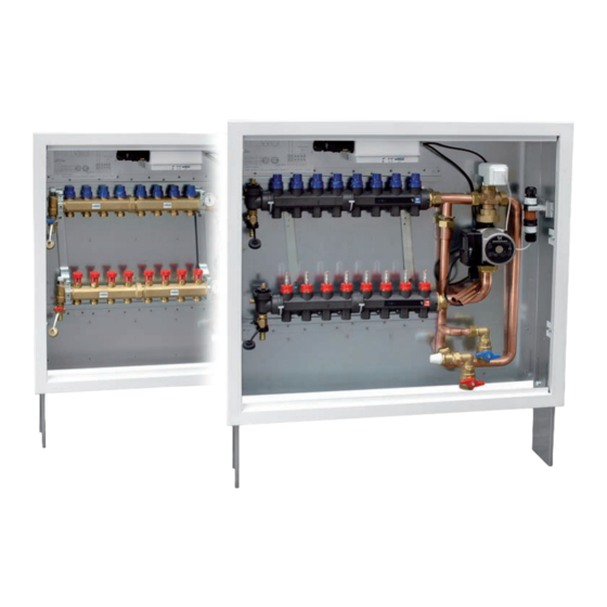
- Page 1 Thermoregulation Termoregolazione KIT VJ TECHNICAL MANUAL MANUALE TECNICO...
-
Page 3: Avvertenze Generali
SAFETY WARNINGS - AVVERTENZE PER LA SICUREZZA Read this manual carefully before installing and/or using the Le g g e re co n at te n z i o n e q u e s to l i b re t to p r i m a equipment and keep it in an accessible place. -
Page 4: Attrezzatura E D.p.i. Necessari
DISPOSAL - SMALTIMENTO In accordance with the provisions of the following In base a quanto previsto dalle seguenti direttive European directives 2011/65/EU, 2012/19/EU europee 2011/65/UE, 2012/19/UE e 2003/108/ and 2003/108/EC, regarding reducing the use of CE, relative alla riduzione dell’uso di sostanze hazardous substances in electrical and electronic pericolose nelle apparecchiature elettriche ed equipment, in addition to waste disposal. -
Page 5: Table Of Contents
INDEX - INDICE Description Descrizione Pag. Safety warnings Avvertenze per la sicurezza General warnings Avvertenze generali Disposal Smaltimento Necessary equipment and ppd Attrezzatura e d.P.I. Necessari Preliminary operations Operazioni preliminari Description Descrizione Content packaging Contenuto imballo Description of the equipment components Descrizione parti apparecchiatura Description of the connections Descrizione attacchi apparecchiatura... -
Page 6: Operazioni Preliminari
PRELIMINARY OPERATIONS - OPERAZIONI PRELIMINARI TESTING, TRANSPORT AND UNPACKAGING ISPEZIONE, TRASPORTO E DISIMBALLO Upon receipt, check immediately that the packaging is intact: All’atto del ricevimento verificare immediatamente l’integrità the machine has left the factory in perfect working order and any dell’imballo: la macchina ha lasciato la fabbrica in perfetto stato, damage must be notified to the carrier immediately and noted on eventuali danni dovranno essere immediatamente contestati... -
Page 7: Descrizione
It can be comandato da una centralina esterna modello RDZ Wi o Trio. combined with RDZ Wi or Trio controllers. It is possible to use È possibile scegliere il kit con collettori serie Control in ottone either Control manifold or Top Composit manifold. -
Page 8: Descrizione Parti Apparecchiatura
DESCRIPTION OF THE EQUIPMENT COMPONENTS DESCRIZIONE PARTI APPARECCHIATURA Appliance parts key Legenda parti apparecchiatura Rif. Description Descrizione Load/discharge cocks Rubinetto di carico / scarico Return manifold Collettore di ritorno Supply and consent plugs Spinotti di alimentazione e consenso Control unit Centralina di controllo Return thermometer Termometro di ritorno... -
Page 9: Descrizione Attacchi Apparecchiatura
DESCRIPTION OF THE CONNECTIONS DESCRIZIONE ATTACCHI APPARECCHIATURA Connection key Legenda attacchi apparecchiatura Rif. Description Descrizione Boiler / Chiller flow connection F 3/4” Mandata da caldaia / chiller F 3/4” Boiler / Chiller return connection F 3/4” Ritorno a caldaia / chiller F 3/4” High temperature flow connection M 3/4”... -
Page 10: Installazione
INSTALLATION - INSTALLAZIONE UNPACKING - DISIMBALLO OVERALL DIMENSIONS - DIMENSIONI DI INGOMBRO N° outlets 3 ÷ 5 6 ÷ 8 9 ÷ 12 N° attacchi A (cm) -
Page 11: Installazioni Possibili
POSSIBLE INSTALLATIONS - INSTALLAZIONI POSSIBILI... -
Page 12: Installazione A Parete
WALL INSTALLATION - INSTALLAZIONE A PARETE... -
Page 14: Collegamenti Idraulici
HYDRAULIC CONNECTIONS - COLLEGAMENTI IDRAULICI °C °C PLUGS FOR BRASS MANIFOLDS TAPPI PER COLLETTORI IN OTTONE • ATTENZIONE • CAUTION Any unused outlets shall be closed with plugs. Tutte le uscite non utilizzate devono essere tappate. - Page 15 PLASTIC PLUGS FOR COLLECTORS TAPPI PER COLLETTORI IN PLASTICA • CAUTION • ATTENZIONE Any unused outlets shall be closed with plugs. Tutte le uscite non utilizzate devono essere tappate. K IT...
-
Page 16: Predisposizione Collegamenti Elettrici
ELECTRICAL CONNECTION SETUP (EXAMPLES) PREDISPOSIZIONE COLLEGAMENTI ELETTRICI (ESEMPI INDICATIVI) -
Page 17: Schema Di Collegamento Elettrico Generale
GENERAL WIRING CONNECTION DIAGRAM SCHEMA DI COLLEGAMENTO ELETTRICO GENERALE Connect according to the diagram and respect the Collegare come da schema e rispettare la polarita’ polarity (phase - neutral). fase - neutro. It’s necessary to install a disconnecting switch on the E’... -
Page 18: Installazione Cavo Messa A Terra
CONNECTION DIAGRAM FOR THE SERVOMOTOR AND SCHEMA DI COLLEGAMENTO SERVOMOTORE E THE DELIVERY SENSOR SONDA DI MANDATA Ahdesive label on the plug Adhesive label on the socket Etichetta adesiva incollata alla spina Etichette adesiva incollata alla presa Mixing Valve Mixing Valve Delivery sensor Servomotor Control Delivery sensor... -
Page 19: Caricamento Dell'impianto
3.10 SYSTEM FILLING - CARICAMENTO DELL’IMPIANTO FILLING FROM THE BOILER FILLING FROM THE MANIFOLD RIEMPIMENTO DALLA CALDAIA RIEMPIMENTO DAL COLLETTORE... - Page 20 FILLING FROM THE BOILER FILLING FROM THE MANIFOLD RIEMPIMENTO DALLA CALDAIA RIEMPIMENTO DAL COLLETTORE 180° 180°...
- Page 21 FILLING FROM THE BOILER FILLING FROM THE MANIFOLD RIEMPIMENTO DALLA CALDAIA RIEMPIMENTO DAL COLLETTORE 180° 180° K IT K IT...
- Page 22 FILLING FROM THE BOILER FILLING FROM THE MANIFOLD RIEMPIMENTO DALLA CALDAIA RIEMPIMENTO DAL COLLETTORE °C °C °C °C...
- Page 23 FILLING FROM THE BOILER FILLING FROM THE MANIFOLD RIEMPIMENTO DALLA CALDAIA RIEMPIMENTO DAL COLLETTORE l/min l/min ° C ° C 4 4 6 4 4 6 4 2 4 4 2 4 8 4 0 8 4 0 3 6 3 3 6 3 2 3 4 2 3 4...
-
Page 24: Messa In Funzione
4 STARTUP - MESSA IN FUNZIONE MAIN FLOW ADJUSTMENT - REGOLAZIONE PORTATA PRINCIPALE KIT VJ SYSTEM WITH HEATING ELEMENTS KIT VJ SYSTEM WITHOUT HEATING ELEMENTS IMPIANTO KIT VJ CON CORPI SCALDANTI IMPIANTO KIT VJ SENZA CORPI SCALDANTI Features for lockshield valve 3/4"... -
Page 25: Dati Tecnici Dei Componenti
5 TECHNICAL DATA OF THE COMPONENTS - DATI TECNICI DEI COMPONENTI CONTROL AND SAFETY ELECTRONIC UNIT CENTRALINA ELETTRONICA DI CONTROLLO E SICUREZZA TECHNICAL FEATURES CARATTERISTICHE TECNICHE 1) Power supply: 230Vca-50Hz. (3CN2-4CN2 clamps). 1) Alimentazione elettrica: 230Vca-50Hz. (Morsetti 3CN2-4CN2). 2) N 2 outlets via relay with voltage free contacts. 2) N. - Page 26 L’attivazione di tale programma si effettua mediante il dip- Dipswitch 6 activates such program (see Table 2). In KIT VJ this switch 6 (vedi Tabella 2). Nel KIT VJ la funzionalità non è operation mode is not used.
- Page 27 HEATING MANAGEMENT GESTIONE DEL RISCALDAMENTO When a heating request occur, the control unit activates both the Quando vi è richiesta di riscaldamento la centralina provvede ad circulation pump; the boiler and the yellow fixed led will light on. attivare l’accensione del circolatore, della caldaia e si accenderà When the heating request (by the thermostat or room in modalità...
-
Page 28: Valvola Miscelante
MIXING VALVE - VALVOLA MISCELANTE MIXING VALVE (V5078) TECHNICAL DATA DATI TECNICI VALVOLA MISCELATRICE (V5078) Static pressure: up to 16 bar Pressione statica: fino a 16 bar Differential pressure: 10 bar Pressione differenziale: 10 bar Leakage: 1% of the Kvs Trafilamento: 1% del Kvs Maximum water temperature:... -
Page 29: Servomotore M7410E
SERVOMOTOR M7410E - SERVOMOTORE M7410E M7410E SERVOMOTOR TECHNICAL DATA DATI TECNICI SERVOMOTORE M7410E Field of application: water Campo di applicazione: acqua Frequency: 50/60 Hz Frequenza: 50/60 Hz Voltage: 24 Vac Tensione: 24 Vac Input signal: 0..10 V (as per standard) Segnale d’ingresso: 0..10 V (di serie) 2..10 V... - Page 30 supplied as standard di serie 100%...0% 0...10V Y=0...+10V 0%...100% 2...10V supplied as standard di serie Y=2...+10V The servomotor electric connections are already made in the I collegamenti elettrici del servomotore sono già eseguiti factory, follow the indications below if the same must be replaced: di fabbrica, in caso di sostituzione dello stesso seguire le indicazioni seguenti: Red Wire:...
-
Page 31: Circolatore Elettronico Autoregolante
SELF-ADJUSTING ELECTRONIC CIRCULATION PUMP CIRCOLATORE ELETTRONICO AUTOREGOLANTE TECHNICAL DATA DATI TECNICI G 1”1/2 G 1”1/2 [mm] 93,5 Glandless circulation pump with a cast iron pump housing and Pompa di circolazione senza ghiandola con corpo in ghisa e threaded connection. EC motor with automatic power adjustment and connessione filettata. - Page 32 Product description and function / Descrizione del prodotto e funzionamento Pump housing with screwed connections Corpo pompa con attacchi filettati Glandless motor Motore a rotore bagnato Condensate drain openings (4x around circumference) Fori di scarico della condensa (4 sul perimetro) Housing screws Viti del corpo Control module...
- Page 33 COMMISSIONING MESSA IN SERVIZIO Commissioning only by qualified technicians. La messa in servizio deve essere effettuata esclusivamente da un tecnico impiantista qualificato. Venting / Sfiato • Fill and vent the system correctly. • Riempire e sfiatare correttamente l’impianto. If the pump does not vent automatically: Se ciò...
- Page 34 Regulation mode for radiant systems Pump curves - Gra ci pompa Modalità di regolazione per impianti radianti Constant pressure - Prevalenza costante p/kPa COSTANT DIFFERENTIAL PRESSURE Δp-c Type of regulation recommended for underfloor heating. The control keeps the set delivery head constant irrespective of the pumped volume flow.
- Page 35 FAULTS - CAUSES - REMEDIES GUASTI - CAUSE - RIMEDI The troubleshooting must only be carried out by a qualified La riparazione dei guasti deve essere eseguita unicamente da specialist, and work on the electrical connection must only be tecnici specializzati qualificati, gli interventi sui collegamenti carried out by a qualified electrician.
- Page 36 Manuale restart / Riavvio Manuale • The pump attempts an automatic restart upon • Quando viene rilevato un blocco, la pompa cerca di detecting a blockage. riavviarsi automaticamente. If the pump does not restart automatically: Se la pompa non si riavvia automaticamente: •...
-
Page 37: Schemi Elettrici
7 WIRING DIAGRAM - SCHEMI ELETTRICI OUTPUT FOR BOILER CONSENT SOCKET 4P+T (NO TENSION) PRESA 4P+T USCITA PER CONSENSO CALDAIA (LIBERA DA TENSIONE) ROOM THERMOSTAT TERMOSTATO AMBIENTE PLUG 3P+T SPINA 3P+T AZZURRO MARRONE GIALLO/VERDE PLUG 4P+T SOCKET 3P+T SPINA 4P+T PRESA 3P+T PUMP POMPA... -
Page 38: Scheda Per L'installatore
NOTES - NOTE... - Page 40 FAG0DC001AB.00 03/2021...
Need help?
Do you have a question about the KIT VJ and is the answer not in the manual?
Questions and answers