Table of Contents
Advertisement
Advertisement
Table of Contents

Related Manuals for AC Infinity CLOUDLINE PRO S Series


Summary of Contents for AC Infinity CLOUDLINE PRO S Series
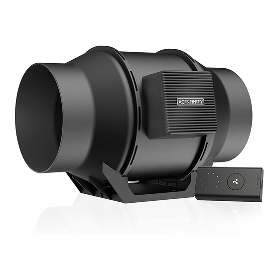
- Page 1 CLOUDLINE PRO MIXED FLOW INLINE FAN SYSTEMS USER MANUAL USER MANUAL...
- Page 3 WELCOME Thank you for choosing AC Infinity. We are committed to product quality and friendly customer service. If you have any questions or suggestions, please don’t hesitate to contact us. Visit www.acinfinity.com and click contact for our contact information. EMAIL LOCATION support@acinfinity.com...
- Page 4 MANUAL CODE CL2207X1 PRODUCT MODEL UPC-A CLOUDLINE PRO S4 AI-CLS4 819137020290 CLOUDLINE PRO S6 AI-CLS6 819137020306 CLOUDLINE PRO S8 AI-CLS8 819137020849 CLOUDLINE PRO S10 AI-CLS10 819137020856 CLOUDLINE PRO S12 AI-CLS12 819137021006 CLOUDLINE PRO T4 AI-CLT4 854759004785 CLOUDLINE PRO T6 AI-CLT6 854759004792 CLOUDLINE PRO T8 AI-CLT8...
-
Page 5: Manual Index
Page 34 Cleaning ..................Page 35 Programming ................. Page 37 Other Settings ................Page 55 Download the App ................. Page 56 Add a Device ................. Page 57 ....................Page 60 Other AC Infinity Products ............. Page 64 Warranty ..................Page 65... -
Page 6: Product Warning
PRODUCT WARNING TO REDUCE THE RISK OF FIRE, ELECTRIC SHOCK, OR INJURY TO PERSONS, OBSERVE THE FOLLOWING: Ensure your power source conforms to the electrical requirements of this product. Check your local code restrictions for additional safety measures that may be needed for a proper code compliant installation. - Page 7 INTERFERENCE from MH and HPS LIGHTS Certain grow light models with HID* ballasts that do not use electromagnetic shielding will create an area of radio frequency interference (RFI). This can distort nearby frequency-sensitive components like internet lines and climate sensors. RFI can be emitted from the ballast’s cords or the ballast itself.
-
Page 8: Key Features
KEY FEATURES QUIET PWM MOTOR STATOR BLADE FANS CONTROLLER 69 PWM-controlled motor features Hydro-mechanical stator Features automation controls precise speed control, reduced blades enable efficient that activate the fan according rotor noise, and energy-efficient airflow delivery in high static to temperature, humidity, EC voltage. -
Page 9: Product Contents
PRODUCT CONTENTS CLOUDLINE PRO S-Series UIS F - 4PIN M WOOD SCREWS CONTROLLER SPEED CONTROLLER ADAPTER (WALL MOUNT) PLATE BOLTS (x1) (x1) (x1) (x2) CLOUDLINE PRO T-Series SMART SENSOR UIS M - 4PIN F WOOD SCREWS CONTROLLER CONTROLLER 69 PROBE (WALL HANG) ADAPTER PLATE BOLTS... - Page 10 PRODUCT CONTENTS...
-
Page 11: Installation
INSTALLATION MOUNTING STEP 1 Unscrew and loosen the metal rings using a Phillips screwdriver and pliers. STEP 2 Remove the motor box from the flange bracket. Remove the wind circle between the motor box and the intake flange. - Page 12 INSTALLATION MOUNTING STEP 3 Use the flange bracket to set your desired fan position. Mark the four mounting holes. STEP 4 Drill four holes into the marked locations. Make sure your mounting area is structurally sound and free from obstruction.
- Page 13 INSTALLATION MOUNTING STEP 5 If you are mounting onto anything other than a wood support or stud, insert the included four wall anchors into the drilled mounting holes. You may need to use a hammer to secure them through the holes. STEP 6 Align the flange bracket’s holes with the wall anchors.
- Page 14 INSTALLATION MOUNTING STEP 7 Place the wind circle back into the intake flange and reposition the metal clamps over the flanges if applicable. STEP 8 Slide the motor box back into the flange bracket, making sure its airflow arrow is pointing in the same direction as the flange bracket’s arrow.
- Page 15 INSTALLATION MOUNTING STEP 9 If installing ducting, use the included duct clamps to secure it to either end of the duct fan, making sure there is a tight seal. Tighten the duct clamps using a flathead screwdriver.
-
Page 16: Hanging - Straps
INSTALLATION HANGING - STRAPS STEP 1 Loop the strap around the bracket and a pole. STEP 2 Slip the strap through the inner ladder lock slot from the bottom. - Page 17 INSTALLATION HANGING - STRAPS STEP 3 Route the strap into the outer ladder lock slot from the top. Adjust the length of the completed loop as needed. STEP 4 Tuck the loose end through the center gap of the ladder lock to secure the loop.
- Page 18 INSTALLATION HANGING - STRAPS STEP 5(a) - Hanging Downward Let the fan hang by the pole once the straps are secure. Make sure the fan's airflow arrow is pointing towards your desired direction. STEP 5(b) - Hanging Upward To hang the fan right-side up, loop and tighten the straps, as shown in steps 1-4, around the pole.
- Page 19 INSTALLATION HANGING - ROPE CLIPS HANGING UPWARD If installing with rope hangers (sold separately), loop the ropes around the flanges and tighten the rope to secure the fan. HANGING DOWNWARD Loop the two rope hangers around a pole and the fan's bracket. Clip the carabiners onto each other.
- Page 20 INSTALLATION MOTOR CAP STEP 1 Unscrew the motor cap using a screwdriver. STEP 2 Rotate the motor cap to your desired orientation. Reapply the screws. Rotating the motor cap will not void your warranty.
-
Page 21: Configuration Setup
INSTALLATION CONFIGURATION SETUP Intake and Exhaust This fan can be used as either an intake fan or an exhaust fan in grow rooms and larger grow tents. To achieve optimal whole space ventilation, the intake fan or opening - if not using a fan - must be situated at a bottom corner of your grow space. - Page 22 POWERING AND SETUP S-SERIES STEP 1 Plug the duct fan’s UIS connector into the speed controller’s port at the bottom. STEP 2 Plug the fan's power cord into a wall outlet. The controller will receive power from the fan to operate.
- Page 23 POWERING AND SETUP T-SERIES STEP 1 Plug your device’s UIS connector into one of the controller's ports. STEP 2 Plug the sensor probe into the controller’s 3.5mm jack. Set the probe near your plants in your grow tent for the most accurate reading. Keep the probe cord away from your HID* grow light ballast's power cord to ensure the controller properly detects climate conditions.
- Page 24 POWERING AND SETUP T-SERIES STEP 3 Plug your device’s power cord into an AC power outlet to power it and the controller. STEP 4 You may use the included tie mounts, wood screws, and wire ties to manage the cords. Secure the tie mounts onto a surface using the wood screws.
-
Page 25: Controller Mounting
CONTROLLER MOUNTING S-SERIES STEP 1 — WALL MOUNTING Locate a spot free of obstruction and secure the anchor into your wall. Twist the wood screw into the anchors. STEP 2 — WALL MOUNTING Hang the controller by the screw using the hole on the backside. -
Page 26: Magnet Mounting
CONTROLLER MOUNTING S-SERIES MAGNET MOUNTING Mount the controller on a steel surface using the magnet located behind the label. PLATE MOUNTING* Screw the controller plate bolts into the slot or mounting holes at the upper half of the plate. Hang the controller by the bolts using the hole on the backside. - Page 27 CONTROLLER MOUNTING T-SERIES STEP 1 — WALL MOUNTING Locate a spot free of obstruction and secure the anchors into your wall. Twist the wood screws into the anchors. STEP 2 — WALL MOUNTING Hang the controller by the screws using the holes on the backside.
- Page 28 CONTROLLER MOUNTING T-SERIES MAGNET MOUNTING You may also mount the controller onto a steel surface using the magnet located behind the label. PLATE MOUNTING* Screw the bolts into the slot or mounting holes at the upper half of the plate. Hang the controller by the bolts using the holes on the backside.
- Page 29 CONTROLLER MOUNTING T-SERIES CORD ARRANGEMENT Cords may be routed into or outside of the kickstand grooves, and through a cut hole behind the controller. KICKSTANDING Open the stand behind the controller to set it tilted on your desktop.
- Page 30 Create independent timers and schedules for customized activation in your desired timeframe. Your grow system can be regulated using your controller hub or remotely on the AC Infinity app (paired with compatible controllers), where you will have access to automation programming and climate data.
-
Page 31: Extension Cable
The expansion dongle will allow you to connect 2 or 4 devices with a single port and can support additional dongles to create more expansion ports (up to 64 units supported with the use of 20 dongles*). Intended for exclusive use with AC Infinity controllers built with UIS ports. UIS M - M... - Page 32 COMPATIBILITY CONTROLLER 69 The CONTROLLER 69 is compatible with AC Infinity fan models that contain EC-motors. An EC-motor fan will have two cords coming out of its motor box for the power and the controller. Note that certain models that previously used DC-motors now contain EC-motors in updated builds.
- Page 33 ADDING MORE FANS The CONTROLLER 69 is built with four ports that enable you to power and control multiple fans at the same time. Compatible with inline fans with EC motors only. See image below for a sample configuration. Multi-Fan Connection INLINE FAN 4"...
-
Page 34: Adding More Devices
ADDING MORE DEVICES USING THE DONGLE Each controller port can support mix-and- matched devices regardless of their size. When using a 2-port or 4-port dongle, plug your first device into Port 1 for the controller to recognize as the primary device. All other devices plugged into the dongle will follow programming intended for the device plugged into Port 1. - Page 35 CLEANING STEP 1 Remove the motor box from the mounting flange. Refer to steps 1-2 on page 11 to learn how to remove the motor box. STEP 2 Use a damp cloth to clear the impeller and fan blades of any dust and debris. Remove the wind circle in between the motor box and input flange.
- Page 36 CLEANING STEP 3 Clear the stator blades of any dust and debris on the opposite end. Clean the area inside the output and exhaust flanges. STEP 4 Secure the motor box onto the mounting flanges. Refer to steps 7-9 on page 14-15 to learn how to secure the motor box.
-
Page 37: Powering On/Off
PROGRAMMING S-SERIES FAN SPEED ADJUSTING The controller features a single button that controls the fan speed from 0-10. Pressing the speed button increases the fan speed in one unit increments. Pressing the button at the 10 setting will set the fan speed back to 0. Fan Speed Indicator POWERING ON/OFF... - Page 38 PROGRAMMING T-SERIES 2. MODE BUTTON 1. PORT BUTTON 3. SETTING BUTTON Cycles through the controller’s modes: Cycles through up to four Cycles through the controller’s OFF, ON, AUTO (4 triggers), TIMER to connected devices. Each device settings: DISPLAY, CLOCK, ON, TIMER to OFF, CYCLE (ON and is programmed independently, or °F/°C, CALIB.
- Page 39 PROGRAMMING T-SERIES PORTS Pressing the port button will cycle through the controller’s available ports: ALL, 1, 2, 3, and 4. Dot indicates the current device. No digit is displayed if a device is not plugged into the corresponding port. ALL PORTS Navigate to the ALL port to set simultaneous programming for all connected devices.
- Page 40 PROGRAMMING T-SERIES CONTROLLER MODES Pressing the mode button will cycle through the controller’s available programming modes: OFF, ON, AUTO (4 triggers), TIMER TO ON, TIMER TO OFF, CYCLE (On and Off), and SCHEDULE (On and Off). OFF MODE Your devices will not run while in this mode. The OFF Mode setting also serves as the minimum level the other modes will run at while triggered OFF.
-
Page 41: Maximum Level
PROGRAMMING T-SERIES ON MODE Your devices will actively run at the level set here, regardless of the probe’s reading. The ON Mode setting also serves as the maximum level the other modes will run at. *Example shown MAXIMUM LEVEL Your devices will run at the level set in ON Mode, as the maximum level, when triggered ON, as well as in the AUTO Mode, CYCLE Mode, TIMER TO ON Mode, TIMER TO OFF... - Page 42 PROGRAMMING T-SERIES AUTO MODE (HIGH TEMPERATURE TRIGGER) Pressing the up or down button sets the high temperature trigger. The devices will activate if the probe’s reading meets or exceeds this threshold. Once triggered, the devices will gradually ramp up to the level set in ON mode.
- Page 43 PROGRAMMING T-SERIES AUTO MODE (HIGH HUMIDITY TRIGGER) Pressing the up or down button sets the high humidity trigger. The devices will activate if the probe’s reading meets or exceeds this threshold. Once triggered, the devices will gradually ramp up to the level set in ON mode. If the probe’s reading falls below this trigger point, the devices will gradually slow down to a stop or at the level set in Any of the four trigger points can activate while...
- Page 44 Make sure to set the appropriate programming for your chosen device(s). Check for active advance programming on the AC Infinity app, and make sure that your transition figure, maximum, and minimum settings are appropriately set. This can alter how quickly your devices ramp up in levels.
- Page 45 PROGRAMMING T-SERIES TIMER TO ON MODE Pressing the up or down button sets a countdown time. Once the timer ends, the devices will trigger to run at the level set in ON Mode. If there is a level set in OFF Mode, the devices will run at that level during the countdown.
- Page 46 PROGRAMMING T-SERIES CYCLE MODE (ON AND OFF) Set an on duration and an off duration for the devices to cycle through continuously. Press the up or down button to first set a duration for the devices to activate. Then press the mode button again and set a duration for the devices to deactivate.
- Page 47 PROGRAMMING T-SERIES SCHEDULE MODE (ON AND OFF) Sets an on clock-time and an off clock-time schedule for the devices to follow daily. Press the up or down button to first set up an on clock-time to trigger ON mode, then press the mode button to set an off clock-time to trigger OFF mode.
- Page 48 PROGRAMMING T-SERIES CONTROLLER SETTINGS Pressing the setting button will cycle through the controller’s available settings: DISPLAY, °F/ °C, CLOCK, CALIB. T°, CALIB. H%, TRANS. T°, and TRANS. H%. DISPLAY SETTING Adjusts the display brightness and auto-dimming. Press the up or down button to cycle through levels 1, 2, 3, A2 and A3;...
-
Page 49: Clock Setting
PROGRAMMING T-SERIES °F/°C SETTING Changes the displayed units to Fahrenheit or Celsius. Press the up or down button to cycle through F and C. All displayed units will automatically convert when adjusting this setting. CLOCK SETTING Adjusts the current clock time. Press the up or down button to increase or decrease the time. - Page 50 PROGRAMMING T-SERIES CALIBRATION TEMPERATURE SETTING Adjusts the temperature reading the sensor probe is measuring. Press the up or down button to increase or decrease the data figure in 2°F (or 1°C) increments. The calibration cycle ranges from -20°F to 20°F (or -10°C to 10°C) and will be applied to the sensor probe’s measurements.
- Page 51 PROGRAMMING T-SERIES TRANSITION TEMPERATURE SETTING Adjusts how gradually your device will shift between levels when triggered ON by the AUTO Mode’s temperature trigger. This will determine how much the probe temperature needs to increase to step up to the next level setting. The higher the transition setting is, the wider the temperature gap is between levels.
- Page 52 PROGRAMMING T-SERIES TRANSITION HUMIDITY SETTING Adjusts how gradually your device will shift between levels when triggered ON by the AUTO Mode’s humidity trigger. This will determine how much the probe humidity needs to increase to step up to the next level setting. The higher the transition setting is, the wider the humidity gap is between levels.
- Page 53 PROGRAMMING T-SERIES ALERT ICONS The alert icons are displayed at the top of the screen. Icons may flash when the controller signals an alert to notify you of any triggered function or alarm. ADVANCE PROGRAMMING Displays when an advance program set in the app is active. "ADV." will appear and override the controller if an automation program is in use.
- Page 54 PROGRAMMING T-SERIES BLUETOOTH Appears when the physical controller is connected to the app via Bluetooth. DISPLAY LOCK ALERT Displays when you lock the controller. The icon will flash and beep if you attempt to adjust the controller while it is still locked. TEMPERATURE/ HUMIDITY ALARM Flashes and beeps with alarm if the temperature/ humidity meet the trigger point set in the app.
-
Page 55: Other Settings
OTHER SETTINGS FACTORY RESET Holding the mode, up, and down buttons together for 5 seconds HOLD + will reset your controller and restore factory settings. This clears all user parameters in each controller mode and setting. CONTROLLER LOCK Holding the setting button will lock the controller in your current mode. -
Page 56: Download The App
Open the smart phone camera and scan the QR code below to download the AC Infinity app. Please visit our website at www.acinfinity.com for more information on the AC Infinity app. Please note: The AC Infinity App’s appearance and features are subject to change, and please refer to our website/QR for the latest instructions. -
Page 57: Add A Device
ADD A DEVICE SETUP AND PAIRING Power your device on before pairing your device with the app. Refer to pages 23-24 for more information regarding controller setup. Tap on the “+” tab to To launch the app, tap on the "Smart add your smart device. - Page 58 ADD A DEVICE Hold the port button for 5 seconds to activate Select CONTROLLER 69 to begin pairing. Bluetooth. Wait for the Bluetooth icon to start flashing on your controller’s screen.
- Page 59 ADD A DEVICE Tap DONE button to complete the Your controller will appear in your pairing process. smart device with a unique ID. E-E000E DONE Please note: When pairing the app around multiple controllers, move your mobile device closer to your desired controller.
- Page 60 What devices are compatible with the CONTROLLER 69? All AC Infinity devices that contain a UIS connector are compatible. If your AC Infinity device has a 4-pin Molex connector and an EC-Motor, it may still be compatible with the use of an UIS adapter to convert its connector to fit with the controller.
- Page 61 CONTROLLER 69 FAQ How do I stop my device from turning on and off too quickly in AUTO MODE? The figure set in the TRANSITION under SETTINGS will determine how the device ramps up in levels when triggered to run in AUTO MODE. Set a transition threshold X. For every multiple of X that has surpassed your trigger point, the device will increase by one level.
- Page 62 CONTROLLER 69 FAQ Will I be able to use this controller with my own fan? The CONTROLLER 69 is only compatible with AC Infinity fans that use EC-motors. Does the controller retain its settings after power is shut off? Yes. If the controller's power is cut off and is powered on afterwards, your settings will remain.
- Page 63 CLOUDLINE PRO FAQ Can I mount this inline duct fan vertically? Yes. The CLOUDLINE PRO can be mounted in any orientation, including vertically. Will I be able to hardwire this fan to my own controller or thermostat? We do not recommend hardwiring or splicing our fan's power wires. Such modifications may compromise electrical safety and will void this product's warranty.
- Page 64 150 lb. weight capacity. Includes a mounting plate to install your AC Infinity controller onto. Carbon Filters The duct carbon filter is designed to eliminate odors and chemicals for grow tents and hydroponic spaces.
-
Page 65: Warranty
WARRANTY This warranty program is our commitment to you, the product sold by AC Infinity will be free from defects in manufacturing for a period of two years from the date of purchase. If a product is found to have a defect in material or workmanship, we will take the appropriate actions defined in this warranty to resolve any issues. - Page 66 No part of the materials including graphics or logos available in this booklet may be copied, photocopied, reproduced, translated or reduced to any electronic medium or machine readable form, in whole or in part, without specific permission from AC Infinity Inc.
- Page 68 www.acinfinity.com...
Need help?
Do you have a question about the CLOUDLINE PRO S Series and is the answer not in the manual?
Questions and answers