Table of Contents
Advertisement
Quick Links
Advertisement
Table of Contents

Related Manuals for AC Infinity CLOUDRAY T10


Summary of Contents for AC Infinity CLOUDRAY T10
- Page 1 CLOUDRAY WHOLE HOUSE FAN SYSTEM USER MANUAL USER MANUAL...
- Page 3 WELCOME Thank you for choosing AC Infinity. We are committed to product quality and friendly customer service. If you have any questions or suggestions, please don’t hesitate to contact us. Visit www.acinfinity.com and click contact for our contact information. EMAIL LOCATION support@acinfinity.com...
- Page 4 MANUAL CODE CR2009X1 PRODUCT MODEL UPC-A CLOUDRAY T10 AC-CRT10 819137021082 CLOUDRAY T12 AC-CRT12 819137021099 CLOUDRAY T14 AC-CRT14 819137021136 CLOUDRAY T16 AC-CRT16 819137021143 CLOUDRAY T18 AC-CRT18 819137021150 SERIOUS INJURY OR DEATH. Please do not touch the fan's impeller and blades. Secure all nearby objects including wires and cables from coming into contact with the fan’s impeller and blades.
-
Page 5: Manual Index
Product Contents ................Page 7 Installation Guide ................Page 8 Mounting ..................Page 9 Powering and Setup ..............Page 18 Cleaning ..................Page 20 Controller Programming ..............Page 21 Other AC Infinity Products ............. Page 36 Warranty ..................Page 37... -
Page 6: Key Features
KEY FEATURES QUIET PWM MOTOR AUTOMATIC SHUTTERS SMART CONTROLLER PWM-controlled motor features Automatic shutters that open Display with probe enables precise speed control, reduced and close in response to monitoring, thermal & humidity rotor noise, and energy efficient airflow. And closes completely control, fan speed control, EC Voltage. -
Page 7: Product Contents
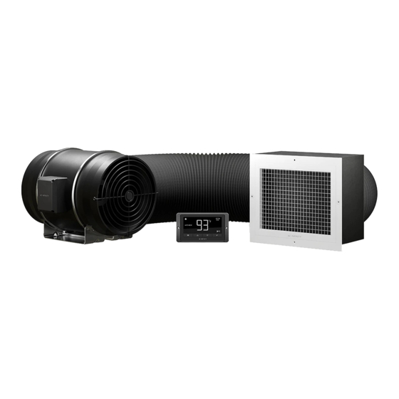
PRODUCT CONTENTS CLOUDRAY WHOLE HOUSE FAN SYSTEM (Included in all series) DUCT FAN DAMPER DUCT SMART SENSOR DUCT SYSTEM BOX & GRILLE TUBE CONTROLLER PROBE CLAMP (x1) (x1) (x1) (x1) (x1) (x2) ROPE CONTROLLER WIRE PROBE DAMPER GRILLE SCREW CLIP SCREW SET MOUNT MOUNT... -
Page 8: Protective Gear
INSTALLATION GUIDE PROTECTIVE GEAR Before you begin, make sure to protect yourself from potential injuries by wearing protective gear including: safety goggles to prevent any drywall dust or insulation from getting in your eyes, gloves to avoid direct contact with insulation, and a dust mask to avoid inhaling dust as a result of cutting into the drywall and insulation. - Page 9 MOUNTING STEP 1 Before installing the whole house fan, find a location in the hallway or staircase central to Ceiling Joist the home. In the attic, mark the corners using grille plate in between the ceiling joists. Then press each corner with a screwdriver or drill until it reaches the other side.
- Page 10 MOUNTING STEP 3 Ceiling Check your location and measurements before cutting into the drywall. Use a drywall saw or jigsaw to cut out the marked location. STEP 4 Remove the white grille plate off the damper box. Place the damper box inside the attic vent side down onto the cut hole, as shown in the image.
- Page 11 MOUNTING STEP 5 Loosely attach the duct tube to the fan to determine the mounting area. Position the fan in an area where you can mount the fan. Remove the duct tube after positioning the fan. As an option you may use the included rope clips to hang your fan from a support beam instead of mounting it.
- Page 12 MOUNTING STEP 7 Double check to make sure the location is structurally sound and free from obstruction. Use a power drill to drill the four mounting holes. STEP 8 If you are mounting onto anything other than a wood support or stud, insert the included four wall anchors into the drilled mounting holes.
- Page 13 MOUNTING STEP 9 Position the mounting flanges and align the mounting holes with the wall anchors. Use a screw driver or drill to secure the four wood screws through the mounting frame and into the wall anchors or stud. Make sure the arrow is pointing in your desired direction.
- Page 14 MOUNTING STEP 11 Secure the motor box back onto the mounting flanges. Make sure the arrow on the motor box points in the same direction as the arrow on the exhaust flange. STEP 12 Connect the duct tube to the intake flange. Secure the duct clamp over the duct tube and tighten it with a flathead screw driver.
- Page 15 MOUNTING STEP 13 Use the included rope clips to support the duct tube. Clip them onto a nearby beam. If there is no beam or an area to hang the rope clips, secure a nail nearby to hook the rope onto. STEP 14 To tighten the rope, pull the loose end until the duct tube feels secured.
- Page 16 MOUNTING Ceiling STEP 15 Place the vent onto the dampener through the opening from below the ceiling. STEP 16 Secure the vent using the included four white screws into the drywall. *Note: The screws will only secure the vent to the ceiling drywall.
- Page 17 MOUNTING STEP 17 Position the controller close to the fan and inside the attic so that the power cord reaches the controller. STEP 18 To mount the controller, use the appropriate screws included for your mounting location.
- Page 18 POWERING AND SETUP STEP 1 Locate the connector plug of the thermal probe and plug it into the bottom of the thermal controller. STEP 2 Secure the sensor probe head, preferably near the hottest area of the attic. Screw in the square tabs once you find a suitable location.
- Page 19 POWERING AND SETUP STEP 3 Connect the molex end from the fan into the bottom of the Universal Controller. Be sure to plug it into the left molex 4 pin connector that has the power and fan icon. This plug is meant to power the controller.
- Page 20 CLEANING STEP 1 Remove the motor box from the mounting flange to remove any dust or build up. Use a damp cloth to clean the dust and dirt off the impeller and fan blades. STEP 2 Clean the dust and dirt off the stator blades on the opposite side.
-
Page 21: Mode Button
PROGRAMMING AUTO HIGH TEMP. LOW TEMP. HIGH HUMID. LOW HUMID. 1. MODE BUTTON This button cycles through each of the controller’s mode: OFF, ON, AUTO (4 triggers), TIMER TO ON, TIMER TO OFF, CYCLE (On and Off), and SCHEDULE (On and Off). 2. - Page 22 PROGRAMMING 5. PROBE HUMIDITY Current humidity that the probe is detecting. Displays “--“ if no probe is plugged in. Includes a trend indicator that signals a rise, steady, or fall in humidity within the last hour. 6. CONTROLLER MODE Displays the mode that the controller is currently in. Pressing the mode button cycles through the available modes.
-
Page 23: Controller Modes
PROGRAMMING CONTROLLER MODES Pressing the mode button will cycle through the controller’s available programming modes: OFF, ON, AUTO (4 triggers), TIMER TO ON, TIMER TO OFF, CYCLE (On and Off), and SCHEDULE (On and Off). OFF MODE Your fan will not run while in this mode. However, the fan speed set while in this mode establishes the minimum speed in the other modes. - Page 24 PROGRAMMING AUTO MODE (LOW TEMPERATURE TRIGGER) Pressing the up or down button sets the low temperature trigger. The fans will activate if the probe’s reading meets or falls below this threshold. Once triggered, the fan will gradually ramp up to the speed set in ON mode.
- Page 25 PROGRAMMING AUTO MODE (LOW HUMIDITY TRIGGER) Pressing the up or down button sets the low humidity trigger. The fans will activate if the probe’s reading meets or falls below this threshold. Once triggered, the fan will gradually ramp up to the speed set in ON mode.
- Page 26 PROGRAMMING TIMER TO OFF MODE In this mode, press the up or down button to set a countdown time. The fans will run at the speed set in ON Mode until the countdown ends. If there was a speed set in OFF Mode other than zero, then the fans will run at that speed after the end of the countdown.
- Page 27 ADV. MODE Advanced programs are automation, alarm, and/ or notification settings created in the AC Infinity controller app. Its icon will display when an advanced program is set but not triggered. “ADV” will appear when an automation advanced program is activated.
-
Page 28: Controller Settings
PROGRAMMING CONTROLLER SETTINGS Pressing the setting button will cycle through the controller’s available settings: DISPLAY, F/C, CLOCK, CALIBRATION TEMPERATURE, CALIBRATION HUMIDITY, TRANSITION TEMPERATURE, and TRANSITION HUMIDITY. DISPLAY SETTING In this setting, adjust the brightness of the display and auto-dimming. Press the up or down button to cycle through 1, 2, 3, A2 and A3. -
Page 29: Clock Setting
PROGRAMMING CLOCK SETTING In this setting, adjust the current clock time. Press the up or down button to increase or decrease the time. Once you cycle through 12:00 each time, the units will automatically change to AM or PM. The current clock time will be shown at the top right corner of display. - Page 30 PROGRAMMING TRANSITION TEMPERATURE SETTING In this setting, adjust the incremental rules in which the fan speed ramps up or down for temperature triggers in AUTO Mode. Press the up or down button to cycle through 0°F to 8°F (or 0°C to 4°C) to set a differential increment.
- Page 31 PROGRAMMING TRANSITION HUMIDITY SETTING In this setting, adjust the incremental rules in which the fan speed ramps up or down for humidity triggers in AUTO Mode. Press the up or down button to cycle through 0% to 8% to set a differential increment. Once setup, when the sensor humidity first meets or exceeds the high humidity trigger, the speed will start at one speed above the speed set in OFF Mode.
- Page 32 PROGRAMMING ALERT ICONS On the top left of the display is the alert icon section. Icons may flash when the controller wishes to alert you that a particular function or alarm is being triggered. ADVANCE PROGRAMMING This icon displays when an advanced program set in the app is active. "ADV." will appear and override the controller if an automation program is in use.
- Page 33 LOW HUMIDITY ALARM This icon will flash and beep with an alert if humidity falls below the trigger point set in the app. Will flash until the humidity rises above the trigger point. TIMER ALERT This icon will flash when a countdown has completed for TIMER TO ON, TIMER TO OFF, CYCLE, or SCHEDULE Mode.
-
Page 34: Other Settings
OTHER SETTINGS FACTORY RESET To reset the controller back to factory settings, hold the mode button, the up button, and the down button simultaneously for four or more seconds. Resetting the controller will clear all user set parameters in every controller mode and settings. BLUETOOTH RESET Hold the Mode and Settings buttons simultaneously for four or more seconds to clear advanced programming in the controller. -
Page 35: Minimum Speed
OTHER SETTINGS MINIMUM SPEED In OFF Mode, you can set the minimum speed in which the fan will run at in other modes. If a speed is higher than 0, then the fan will run at that speed when it is triggered to be off. AUTO INCREASING OR DECREASING Holding the up or down button will increase or decrease user parameters automatically until the user releases the up or down button. - Page 36 AC INFINITY PRODUCTS Register Booster Fans The AIRTAP series is a line of register booster fans designed to quietly increase airflow coming from your central heat and air conditioning systems, increasing comfort for your home. Features a thermal controller with intelligent programming that will automatically adjust airflow strength in response to heating and cooling temperatures you have set.
-
Page 37: Warranty
WARRANTY This warranty program is our commitment to you, the product sold by AC Infinity will be free from defects in manufacturing for a period of two years from the date of purchase. If a product is found to have a defect in material or workmanship, we will take the appropriate actions defined in this warranty to resolve any issues. - Page 38 No part of the materials including graphics or logos available in this booklet may be copied, photocopied, reproduced, translated or reduced to any electronic medium or machine readable form, in whole or in part, without specific permission from AC Infinity Inc.
- Page 40 www.acinfinity.com...
Need help?
Do you have a question about the CLOUDRAY T10 and is the answer not in the manual?
Questions and answers