Advertisement
Advertisement
Table of Contents

Subscribe to Our Youtube Channel
Related Manuals for AC Infinity AC-TWT8


Summary of Contents for AC Infinity AC-TWT8
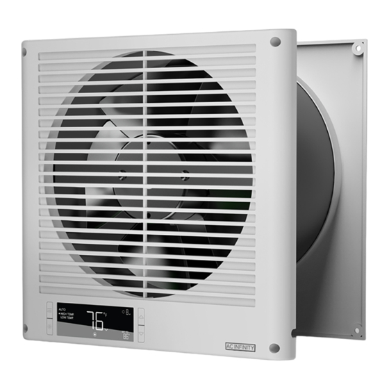
- Page 1 THROUGH-WALL FAN WITH TEMPERATURE CONTROLS USER MANUAL...
- Page 3 WELCOME Thank you for choosing AC Infinity. We are committed to product quality and friendly customer service. If you have any questions or suggestions, please don’t hesitate to contact us. Visit www. acinfinity.com and click contact for our contact information.
- Page 4 MANUAL CODE TWT2201X1 PRODUCT MODEL UPC-A Through-Wall Fan AC-TWT8 819137023338...
-
Page 5: Table Of Contents
................. Page 7 Product Contents ................Page 8 Installation ..................Page 9 Installation: Hardwiring ..............Page 16 Programming ................. Page 19 Other Settings ................Page 29 ....................Page 30 Other AC Infinity Products ............. Page 31 Warranty ..................Page 32... -
Page 6: Product Warning
PRODUCT WARNING TO REDUCE THE RISK OF FIRE, ELECTRIC SHOCK, OR INJURY TO PERSONS, OBSERVE THE FOLLOWING: Ensure your power source conforms to the electrical requirements of this product. Check your local code restrictions for additional safety measures that may be needed for a proper code compliant installation. -
Page 7: Key Features
KEY FEATURES HEAVY-DUTY BUILD NEXT-GEN MOTOR DUAL-BALL BEARINGS Durable, fire-resistant ABS Features an innovative EC motor Enables unit to be mounted faceplate with internal steel that uses pulsing to control its in any direction. Motor structure shields the fan blades speed. -
Page 8: Product Contents
PRODUCT CONTENTS THROUGH-WALL REAR WOOD SCREWS FACEPLATE (WALL HANG) (x1) (x1) (x8) FRONT FACEPLATE REAR FACEPLATE WIRE STENCIL STENCIL MOUNT (x1) (x1) (x1) -
Page 9: Installation
INSTALLATION STEP 1 Determine your desired mounting location free of obstruction (studs, waterlines, electrical cords, etc.). Make sure this mounting location is 3.5 to 6 inches thick. Mark the center point, mounting points, and cylinder outline using the rear faceplate stencil. STEP 2 From the center point, measure the length to the end of your wall (X) and the height to the... - Page 10 INSTALLATION STEP 3 Drill the mounting holes into your wall. Cut the circular outline to create the opening. Use of a saw is recommended. STEP 4 Secure the included anchors into the mounting holes.
- Page 11 INSTALLATION STEP 5 Insert the rear faceplate into the circular cutout, making sure the mounting holes line up. STEP 6 Drill the wood screws into the anchors to secure the rear faceplate.
- Page 12 INSTALLATION STEP 7 Mark the center point of the front faceplate stencil on the other side of your wall using the length (X) and height (Y) measurements from step 2. STEP 8 Place the stencil over the center point and mark the mounting points and cylinder outline.
- Page 13 INSTALLATION STEP 9 Drill the mounting holes into your wall. Cut the circular outline to create the opening. Use of a saw is recommended. STEP 10 Secure the included anchors into the mounting holes.
- Page 14 INSTALLATION STEP 9 Insert the front faceplate into the circular cutout, making sure the mounting holes line up. Its cylinder should easily slide into the rear faceplate's cylinder. STEP 10 Route the power cord through the opening on the lower right corner so the front faceplate is flush against the wall.
- Page 15 INSTALLATION STEP 11 Drill the wood screws into the anchors to secure the front faceplate. STEP 12 Plug the AC power cord into a wall outlet to power the fan.
-
Page 16: Installation: Hardwiring
INSTALLATION HARDWIRING Power from all sources involved in this step must be completely shut before proceeding. STEP 1 If your fan is plugged in, make sure to unplug it from its power socket. Locate your home's main electrical panel and flip the your room's circuit breaker to OFF. - Page 17 INSTALLATION HARDWIRING STEP 1 Unscrew the leftmost panel to access the power cord wires. STEP 2 Unscrew the left three bolts to release the power cord wires. Use the following as a reference: Black: Live Wire Green: Ground Wire White: Neutral Wire...
- Page 18 INSTALLATION STEP 3 Remove the power cord and its wires from the fan's junction box. STEP 4 Route your house's wires into the fan's junction box, making sure the correct colored wires are inserted into each rail. Screw in the bolts to secure the wires and the panel over the junction box.
-
Page 19: Programming
PROGRAMMING 2. SETTING BUTTON 1. MODE BUTTON 3. UP/DOWN BUTTONS Cycles through the controller’s Cycles through the controller’s modes: Adjusts the value of your current settings: DISPLAY, °F/°C, CALIB. T°, OFF, ON, AUTO (High Temperature mode. The up button increases and TRANS. - Page 20 PROGRAMMING SWITCHING AIRFLOW DIRECTION The through-wall fan is capable of producing either intake or exhaust airflow. Holding the setting and up/down buttons together will switch the airflow direction between INTAKE and EXHAUST, respectively. INTAKE Holding the setting and up buttons together for 3 seconds will switch the airflow direction to the intake configuration.
- Page 21 PROGRAMMING CONTROLLER MODES Pressing the mode button will cycle through the controller’s available programming modes: OFF, ON, AUTO (High Temperature and Low Temperature), TIMER TO ON, TIMER TO OFF, and CYCLE (On and Off). OFF MODE (MINIMUM LEVEL) Your fan will not run while in this mode. The fan speed set while in this mode establishes the minimum speed in other modes.
- Page 22 PROGRAMMING AUTO MODE (HIGH TEMPERATURE TRIGGER) Pressing the up or down button sets the high temperature trigger. The fans will activate if the probe’s reading meets or exceeds this threshold. Once triggered, the fan will gradually ramp up to the speed set in ON mode.
- Page 23 PROGRAMMING TIMER TO ON MODE Pressing the up or down button sets a countdown time. Once the timer ends, the fans will trigger to run at the speed set in ON Mode. If there is a speed set in OFF Mode, the fans will run at that speed during the countdown.
- Page 24 PROGRAMMING CYCLE MODE (ON AND OFF) Set an on duration and an off duration for the fan to cycle through continuously. Press the up or down button to first set a duration for the fan to activate. Then press the mode button again and set a duration for the fan to deactivate.
- Page 25 PROGRAMMING CONTROLLER SETTINGS Pressing the setting button will cycle through the controller’s available settings: DISPLAY, °F/ °C, CALIB. T°, and TRANS. T. DISPLAY SETTING Adjusts the display brightness and auto-dimming. Press the up or down button to cycle through levels 1, 2, 3, A2 and A3;...
- Page 26 PROGRAMMING °F/°C SETTING Changes the displayed units to Fahrenheit or Celsius. Press the up or down button to cycle through F and C. All displayed units will automatically convert when adjusting this setting. CALIBRATION TEMPERATURE SETTING Adjusts the temperature reading the sensor probe is measuring.
- Page 27 PROGRAMMING TRANSITION TEMPERATURE SETTING Adjusts the transition threshold between the fan speeds in the AUTO Mode temperature triggers. Press the up or down button to cycle through 0°F to 8°F (0°C to 4°C) and set a transition threshold. The fan speed will be set one level above the OFF Mode speed when the sensor temperature first meets or exceeds the high temperature trigger.
- Page 28 PROGRAMMING ALERT ICONS The alert icons are displayed at the top of the screen. Icons may flash when the controller signals an alert to notify you of any triggered function. TIMER ALERT Flashes when a countdown has completed for TIMER TO ON, TIMER TO OFF, or CYCLE Mode.
-
Page 29: Other Settings
OTHER SETTINGS FACTORY RESET Holding the mode, up, and down buttons together for 5 seconds HOLD + will reset your controller and restore factory settings. This clears all user parameters in each controller mode and setting. CONTROLLER LOCK Holding the setting button will lock the controller in your current mode. -
Page 30: Faq
THROUGH-WALL FAN FAQ How do I find any studs, drains, and other obstructions in my wall? Use a portable sensor such as a stud finder to find any obstructions before installing this fan. What other tools do I need to install this fan? We recommend using the following tools to install the through-wall fan: pencil, ruler, tape measure, screwdriver, drill, drywall saw, and stud finder. -
Page 31: Other Ac Infinity Products
AC INFINITY PRODUCTS RACK FANS The CLOUDPLATE series rack fan system is designed for quietly cooling a wide range of audio, video, home theater, network, and IT equipments racks. The model features a thermal controller with intelligent programming that will automatically adjust the fan speeds in response to changing temperatures. -
Page 32: Warranty
WARRANTY This warranty program is our commitment to you, the product sold by AC Infinity will be free from defects in manufacturing for a period of two years from the date of purchase. If a product is found to have a defect in material or workmanship, we will take the appropriate actions defined in this warranty to resolve any issues. - Page 33 No part of the materials including graphics or logos available in this booklet may be copied, photocopied, reproduced, translated or reduced to any electronic medium or machine readable form, in whole or in part, without specific permission from AC Infinity Inc.
Need help?
Do you have a question about the AC-TWT8 and is the answer not in the manual?
Questions and answers