Table of Contents
Advertisement
Advertisement
Table of Contents

Related Manuals for AC Infinity AIRLIFT Series


Summary of Contents for AC Infinity AIRLIFT Series
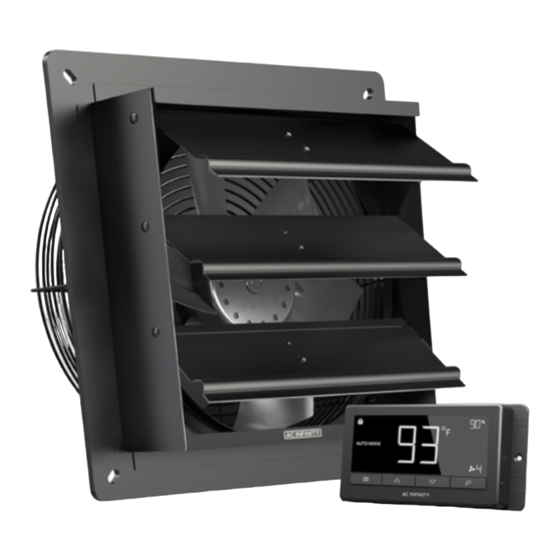
- Page 1 AIRLIFT SERIES SHUTTER EXHAUST FAN SYSTEM USER MANUAL USER MANUAL...
- Page 3 WELCOME Thank you for choosing AC Infinity. We are committed to product quality and friendly customer service. If you have any questions or suggestions, please don’t hesitate to contact us. Visit www.acinfinity.com and click contact for our contact information. EMAIL LOCATION support@acinfinity.com...
- Page 4 MANUAL CODE AL2104X1 PRODUCT MODEL UPC-A AIRLIFT S10 AC-ALS10 819137021433 AIRLIFT S12 AC-ALS12 819137021440 AIRLIFT S14 AC-ALS14 819137021457 AIRLIFT S16 AC-ALS16 819137021464 AIRLIFT T10 AC-ALT10 819137020900 AIRLIFT T12 AC-ALT12 819137020917 AIRLIFT T14 AC-ALT14 819137020924 AIRLIFT T16 AC-ALT16 819137020948 AIRLIFT T18 AC-ALT18 819137020948 AIRLIFT T20...
-
Page 5: Manual Index
Product Contents ................Page 7 Installation .................. Page 8 Powering and Setup ..............Page 11 Daisy Chain and Setup ..............Page 14 Programming .................. Page 15 Other Settings.................. Page 28 Other AC Infinity Products ............. Page 30 Warranty ..................Page 31... -
Page 6: Key Features
KEY FEATURES HEAVY DUTY BUILD EFFICIENT EC-MOTOR SMART CONTROLLER Fans are enclosed in PWM controlled EC-motor Fetures automation controls steel and wire guards to enables precise speed control, that activate the fan according withstand shocks and harsh low noise, and higher energy to temperature, humidity, environments. -
Page 7: Product Contents
PRODUCT CONTENTS AIRLIFT S-SERIES SPEED MACHINE SCREWS WOOD SCREWS CONTROLLER (WALL MOUNT) (WALL MOUNT) (x2) (x2) (x1) AIRLIFT T-SERIES SMART SENSOR MACHINE SCREWS WOOD SCREWS WOOD SCREWS CONTROLLER PROBE (WALL MOUNT) (WALL MOUNT) (WALL HANG) (x1) (x1) (x2) (x2) (x2) FAN UNIT WIRE SHUTTER... -
Page 8: Installation
INSTALLATION STEP 1 When installing in a large room like a green house, barn, or garage, it is recommended that the shutter fan should be mounted on the Mounting Hole opposite side of any ventilation openings for better air circulation. The fan should also be positioned higher in the room to exhaust out heated air, which will rise on its own due to natural convection. - Page 9 INSTALLATION STEP 3 Depending on your mounting surface material, use the appropriate tools to cut into the wall. Use a drill or a hand saw to create an opening large enough to insert a saw blade or jigsaw inside the outlined area of the wall panel. Thinner Woods or Plastic Woods, Tougher Plastic or, Metal STEP 4...
- Page 10 INSTALLATION STEP 5 From inside the room, position the shutter fan back into the opening of the fan. Make sure the controller connectors and power cord is on the inside of the room. Then, use the included hardware to secure the fan. If you are using your own shutter, remove the AIRLIFT's shutter by unscrewing the nuts and bolts from the fan guard.
- Page 11 POWERING AND SETUP S-SERIES STEP 1 Plug the shutter fan’s 4-pin Molex connector into the speed controller’s port at the top. STEP 2 Plug the fans power cord into an AC power outlet to power the fan and controller.
- Page 12 POWERING AND SETUP T-SERIES STEP 1 Locate the connector plug of the sensor probe and plug it into the bottom of the thermal controller. STEP 2 Secure the sensor probe head near by, preferably in the hottest area of the room. You can use the wire tie to secure the probe away from the fan blades.
- Page 13 POWERING AND SETUP T-SERIES STEP 3 Connect the Molex end from the fan into the bottom of the controller. STEP 4 Plug the fans power cord into an AC power outlet to power the fan and controller.
- Page 14 (The illustration below is for T-Series model only. ) The controller included is compatible with AC Infinity fan models that contain an EC-motor. Typically, EC-motor fans will have a separate cord coming out of it for the power and the controller.
-
Page 15: Powering On And Off
PROGRAMMING FAN SPEED ADJUSTING The controller features a single button that controls the fan speed from 0-8. Pressing the speed button increases the fan speed in one unit increments. Pressing the button at the 8 setting will set the fan speed back to 0. Fan Speed Indicator POWERING ON AND OFF... - Page 16 PROGRAMMING 1. MODE BUTTON 2. UP/DOWN BUTTONS 3. SETTING BUTTON Cycles through the controller’s Adjusts the value of your current Cycles through the controller’s available modes: OFF, ON, AUTO mode. The up button increases and available settings: DISPLAY, °F/ °C, (4 triggers), TIMER TO ON, TIMER down button decreases the setting.
-
Page 17: Controller Modes
PROGRAMMING CONTROLLER MODES Pressing the mode button will cycle through the controller’s available programming modes: OFF, ON, AUTO (4 triggers), TIMER TO ON, TIMER TO OFF, CYCLE (On and Off), and SCHEDULE (On and Off). OFF MODE Your fan will not run while in this mode. However, the fan speed set while in this mode establishes the minimum speed in other modes. - Page 18 PROGRAMMING AUTO MODE (LOW TEMPERATURE TRIGGER) Pressing the up or down button sets the low temperature trigger. The fans will activate if the probe’s reading meets or falls below this threshold. Once triggered, the fan will gradually ramp up to the speed set in ON mode.
- Page 19 PROGRAMMING AUTO MODE (LOW HUMIDITY TRIGGER) Pressing the up or down button sets the low humidity trigger. The fans will activate if the probe’s reading meets or falls below this threshold. Once triggered, the fan will gradually ramp up to the speed set in ON mode.
- Page 20 PROGRAMMING TIMER TO OFF MODE Pressing the up or down button sets a countdown time. The fans will run at the speed set in ON Mode until the countdown ends. If there is a speed set in OFF Mode, the fans will run at that speed after the end of the countdown.
- Page 21 PROGRAMMING SCHEDULE MODE (ON AND OFF) Sets an on clock-time and an off clock-time schedule for the fan to follow daily. Press the up or down button to first set up an on clock-time to trigger ON mode, then press the mode button to set an off clock-time to trigger OFF mode.
-
Page 22: Controller Settings
PROGRAMMING CONTROLLER SETTINGS Pressing the setting button will cycle through the controller’s available settings: DISPLAY, °F/ °C, CLOCK, CALIB. T°, CALIB. H%, TRANS. T°, and TRANS. H%. DISPLAY SETTING Adjusts the display brightness and auto-dimming. Press the up or down button to cycle through levels 1, 2, 3, A2 and A3;... -
Page 23: Clock Setting
PROGRAMMING CLOCK SETTING Adjusts the current clock time. Press the up or down button to increase or decrease the time. Once you cycle through 12:00 each time, the units will automatically change to AM or PM. The clock time is located at the top right corner of the display. - Page 24 PROGRAMMING TRANSITION TEMPERATURE SETTING Adjusts the transition threshold between the fan speeds in the AUTO Mode temperature triggers. Press the up or down button to cycle through 0°F to 8°F (0°C to 4°C) and set a transition threshold. The fan speed will be set one level above the OFF Mode speed when the sensor temperature first meets or exceeds the high temperature trigger.
- Page 25 PROGRAMMING TRANSITION HUMIDITY SETTING Adjusts the transition threshold between the fan speeds in the AUTO Mode humidity triggers. Press the up or down button to cycle through 0% to 8% to set a transition threshold. The fan speed will be set one level above the OFF Mode speed when the sensor humidity first meets or exceeds the high temperature trigger.
- Page 26 PROGRAMMING ALERT ICONS The alert icons are displayed at the top of the screen. Icons may flash when the controller signals an alert to notify you of any triggered function or alarm. ADVANCE PROGRAMMING Displays when an advance program set in the app is active. "ADV." will appear and override the controller if an automation program is in use.
- Page 27 PROGRAMMING LOW HUMIDITY ALARM Flashes and beeps with an alert if the humidity falls below the trigger point set in the app. Continues to flash until the humidity rises above the trigger point. TIMER ALERT Flashes when a countdown has completed for TIMER TO ON, TIMER TO OFF, CYCLE, or SCHEDULE Mode.
-
Page 28: Other Settings
OTHER SETTINGS FACTORY RESET Holding the mode, up, and down buttons together for 5 sec- onds will reset your controller and restore factory settings. This HOLD + clears all user parameters in each controller mode and setting. CONTROLLER LOCK Holding the setting button will lock the controller in your cur- rent mode. -
Page 29: Bluetooth Reset
OTHER SETTINGS AUTO INCREASING OR DECREASING HOLD + Holding the up or down button will increase or decrease the HOLD + user setting automatically until you release them. BLUETOOTH RESET Hold the mode and settings buttons simultaneously for 5 seconds to clear advance programming from the controller. HOLD + The app will disconnect from the controller and will have to be paired again to re-establish Bluetooth connection. - Page 30 AC INFINITY PRODUCTS Register Booster Fans The AIRTAP series is a line of register booster fans designed to quietly increase airflow coming from your central heat and air conditioning systems, increasing comfort for your home. Features a thermal controller with intelligent programming that will automatically adjust airflow strength in response to heating and cooling temperatures you have set.
-
Page 31: Warranty
WARRANTY This warranty program is our commitment to you, the product sold by AC Infinity will be free from defects in manufacturing for a period of two years from the date of purchase. If a product is found to have a defect in material or workmanship, we will take the appropriate actions defined in this warranty to resolve any issues. - Page 32 No part of the materials including graphics or logos available in this booklet may be copied, photocopied, reproduced, translated or reduced to any electronic medium or machine readable form, in whole or in part, without specific permission from AC Infinity Inc.
- Page 36 www.acinfinity.com...
Need help?
Do you have a question about the AIRLIFT Series and is the answer not in the manual?
Questions and answers