AC Infinity CLOUDLINE Series User Manual
Mixed flow duct fan systems
Hide thumbs
Also See for CLOUDLINE Series:
- User manual (16 pages) ,
- User manual (41 pages) ,
- User manual
Table of Contents
Advertisement
Advertisement
Table of Contents

Related Manuals for AC Infinity CLOUDLINE Series


Summary of Contents for AC Infinity CLOUDLINE Series
- Page 1 CLOUDLINE MIXED FLOW DUCT FAN SYSTEMS USER MANUAL USER MANUAL...
- Page 3 WELCOME Thank you for choosing AC Infinity. We are committed to product quality and friendly customer service. If you have any questions or suggestions, please don’t hesitate to contact us. Visit www.acinfinity.com and click contact for our contact information. EMAIL LOCATION support@acinfinity.com...
- Page 4 MANUAL CODE CL1910X1 PRODUCT MODEL UPC-A CLOUDLINE S4 AI-CLS4 819137020290 CLOUDLINE S6 AI-CLS6 819137020306 CLOUDLINE S8 AI-CLS8 819137020849 CLOUDLINE S10 AI-CLS10 819137020856 CLOUDLINE S12 AI-CLS12 819137021006 CLOUDLINE T4 AI-CLT4 854759004785 CLOUDLINE T6 AI-CLT6 854759004792 CLOUDLINE T8 AI-CLT8 819137020276 CLOUDLINE T10 AI-CLT10 819137020283 CLOUDLINE T12...
-
Page 5: Table Of Contents
Page 5 Key Features ................. Page 6 Product Contents ................Page 7 Installation (Mounting) ..............Page 9 Installation (Configuration Setup) ..........Page14 Powering ..................Page 16 Programming ................. Page 25 Other AC Infinity Products ............. Page 33 Warranty ..................Page 34... -
Page 6: Key Features
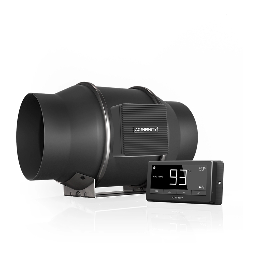
KEY FEATURES QUIET PWM MOTOR STATOR BLADE FANS SMART CONTROLLER PWM-controlled motor features Hydro-mechanical stator Controls and monitors temp. precise speed control, reduced blades enable efficient airflow and humidity using included rotor noise, and energy-efficient delivery in high static pressure probe. -
Page 7: Product Contents
PRODUCT CONTENTS CLOUDLINE S-Series DUCT FAN CONTROLLER SYSTEM SCREW SET (x1) (x2) CLOUDLINE T-Series SMART SENSOR MACHINE WOOD CONTROLLER CONTROLLER PROBE SCREWS SCREWS SCREW SET (x1) (x1) (x2) (x2) (x2) CLOUDLINE S-Series/T-Series (Included in Both Series) DUCT FAN DUCT WIRE CABLE TIE WALL DUCT FAN... - Page 8 PRODUCT CONTENTS...
-
Page 9: Installation (Mounting)
INSTALLATION MOUNTING STEP 1 Unscrew and loosen the metal rings using a Phillips screwdriver and pliers. STEP 2 Remove the motor box from the flange bracket. Remove the wind circle between the motor box and the intake flange. - Page 10 INSTALLATION MOUNTING STEP 3 Use the flange bracket to set your desired fan position. Mark the four mounting holes. STEP 4 Drill four holes into the marked locations. Make sure your mounting area is structurally sound and free from obstruction.
- Page 11 INSTALLATION MOUNTING STEP 5 If you are mounting onto anything other than a wood support or stud, insert the included four wall anchors into the drilled mounting holes. You may need to use a hammer to secure them through the holes. STEP 6 Align the flange bracket’s holes with the wall anchors.
- Page 12 INSTALLATION MOUNTING STEP 7 Place the wind circle back into the intake flange and reposition the metal clamps over the flanges if applicable. STEP 8 Slide the motor box back into the flange bracket, making sure its airflow arrow is pointing in the same direction as the flange bracket’s arrow.
- Page 13 INSTALLATION MOUNTING STEP 9 Place the metal rings back onto the flanges and tighten the screws back to secure the fan. STEP 10 If installing ducting, use the included duct clamps to secure it to either end of the duct fan, making sure there is a tight seal.
-
Page 14: Installation (Configuration Setup)
INSTALLATION CONFIGURATION SET-UP STEP 11(a) - Hanging Upward If installing with rope hangers (sold separately), loop the ropes around the flanges and tighten the rope to secure the fan. STEP 11(b) - Hanging Downward You may also hang the fan by looping the rope hangers around its mounting plate. - Page 15 INSTALLATION CONFIGURATION SET-UP Intake and Exhaust This fan can be used as either an intake fan or an exhaust fan in grow rooms and larger grow tents. To achieve optimal whole space ventilation, the intake fan or opening - if not using a fan - must be situated at a bottom corner of your grow space.
-
Page 16: Powering
POWERING AND SETUP S-SERIES STEP 1 Plug the duct fan’s 4-pin molex connector into the speed controller’s port at the top. STEP 2 Lastly, to power both the fan and controller, plug the fans power cord into an AC power outlet. (For EC Motor fans only) - Page 17 POWERING AND SETUP T-SERIES STEP 1 You may cable manage the cords using tie mounts, wood screws, and zip ties included with this fan. Secure the tie mounts onto a surface using the wood screws. Loop the zip ties around the cords into the tie mounts.
- Page 18 POWERING AND SETUP T-SERIES STEP 3 Plug the sensor probe into the controller’s 3.5mm jack. Set the probe near your plants in your grow tent for the most accurate reading. STEP 4 Lastly, to power both the fan and controller, plug the fans power cord into an AC power outlet.
- Page 19 ADDING MORE FANS DC/EC Motors To find out your fan's motor type, look at its power cord(s). DC-motor CLOUDLINE fans have one female molex connector cord and include an AC adapter that must be plugged into the controller and an outlet. EC-motor CLOUDLINE fans have two cords, featuring a molex connector and a three-pronged power plug that directly connects to an outlet.
- Page 20 ADDING MORE FANS The smart controller for the CLOUDLINE T-Series has an additional port so that you can add an S-Series fan to power and control two fans together. Please see below for limitations. T-SERIES CONTROLLER Smart controllers for T-Series models with DC motors can support two fans of the same tier model. For example, the CLOUDLINE T4 can only support an S4 fan, the CLOUDLINE T6 can only support an S6 fan and so on.
- Page 21 CLEANING STEP 1 Remove the motor box from the mounting flange. Refer to steps 1 and 2 to learn how to remove the motor box. (Refer to steps 1 and 2 of the mounting installation section to learn how to remove the motor box). STEP 2 Use a damp cloth to clear the impeller and fan blades of any dust and debris.
- Page 22 CLEANING STEP 3 Clear the stator blades of any dust and debris on the opposite end. Clean the area inside the output and exhaust flanges. STEP 4 Secure the motor box onto the mounting flanges. Refer to step 7-9 to learn how to secure the motor box.
- Page 23 CONTROLLER PROGRAMMING FAN SPEED ADJUSTING The controller features a single button that controls the fan speed from 0-8. Pressing the speed button increases the fan speed in one unit increments. Pressing the button at the 8 setting will set the fan speed back to 0. Fan Spee d Indicato r POWERING ON/OFF...
- Page 24 PROGRAMMING 1. MODE BUTTON 3. LEAF BUTTON 2. UP / DOWN BUTTON Cycles through the control- Adjusts the settings of the Turns the screen off ler's temperature/humidity mode that you are in. Up while programs run in the programming: ON, OFF, background.
-
Page 25: Programming
PROGRAMMING MODE SETTING Pressing the Mode button will cycle through the controller’s available programming modes and settings: ON Mode, OFF Mode, TIMER Mode, AUTO Mode (4 triggers), ALARM Settings (4 settings). ON MODE In this mode, the fan will heat continuously regardless of temperature or humidity. - Page 26 PROGRAMMING TRIGGER MODE: HIGH TEMPERATURE In this mode, pressing the up or down button sets the high temperature trigger. The fan will activate if the probe’s reading meets or exceeds this trigger. It will gradually ramp up until it reaches the ON Mode’s setting.
- Page 27 PROGRAMMING TRIGGER MODE: HIGH HUMIDITY In this mode, pressing the up or down button sets a high humidity trigger. The fan will activate if the probe’s reading meets or exceeds this trigger. It will gradually ramp up until it reaches the ON Mode’s setting.
- Page 28 PROGRAMMING ALARM SETTING: HIGH TEMPERATURE In this mode, pressing the up and down button sets a high temperature alarm. The alarm will sound and its icon will flash if the probe’s read- ing exceeds the set temperature. To activate the alarm, leave the alarm mode. The alarm will turn OFF if the probe’s reading Note that alarm triggers can only falls below the trigger or if any button is...
- Page 29 PROGRAMMING ALARM SETTING: HIGH HUMIDITY In this mode, pressing the up and down button sets a high humidity alarm. The alarm will sound and its icon will flash if the probe’s reading exceeds the set humidity. To activate the alarm, leave the alarm mode. The alarm will turn OFF if the probe’s reading Note that alarm triggers can only falls below the trigger or if any button is...
- Page 30 PROGRAMMING FAHRENHEIT OR CELSIUS To switch between Fahrenheit and Celsius readings, set the controller to OFF Mode. Hold the up button to switch to Fahrenheit (°F) and the down button to switch to Celsius (°C). DISPLAY BRIGHTNESS To adjust the brightness of the display, set the controller to OFF Mode, then press the up or down button to increase or decrease the brightness level.
-
Page 31: Warranty
PROGRAMMING ALERT ICONS The top left of the display shows the alert icons. Icons may flash when the controller signals an alert to tell you a particular function or alarm is being triggered. DISPLAY LOCK ALERT This icon is visible when the controller has been locked. The icon will flash to alert you that the controller is locked if you try to change the mode or settings. - Page 32 AC INFINITY PRODUCTS Register Booster Fans The AIRTAP series is a line of register booster fans designed to quietly increase airflow coming from your central heat and air conditioning systems, increasing comfort for your home. Features a thermal controller with intelligent programming that will automatically adjust airflow strength in response to heating and cooling temperatures you have set.
- Page 33 WARRANTY This warranty program is our commitment to you, the product sold by AC Infinity will be free from defects in manufacturing for a period of two years from the date of purchase. If a product is found to have a defect in material or workmanship, we will take the appropriate actions defined in this warranty to resolve any issues.
- Page 34 No part of the materials including graphics or logos available in this booklet may be copied, photocopied, reproduced, translated or reduced to any electronic medium or machine readable form, in whole or in part, without specific permission from AC Infinity Inc.
- Page 36 www.acinfinity.com...
Need help?
Do you have a question about the CLOUDLINE Series and is the answer not in the manual?
Questions and answers