Table of Contents
Advertisement
Quick Links
a
FEATURES
+5 V Power Supply
50 MHz Speed
On-Chip SINE Look-Up Table
On-Chip 10-Bit DAC
Parallel Loading
Power-Down Option
72 dB SFDR
250 mW Power Consumption
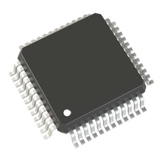
48-Pin QFP
L
APPLICATIONS
DDS Tuning
Digital Demodulation
MCLK
FSELECT
REV. B
Information furnished by Analog Devices is believed to be accurate and
reliable. However, no responsibility is assumed by Analog Devices for its
use, nor for any infringements of patents or other rights of third parties
which may result from its use. No license is granted by implication or
otherwise under any patent or patent rights of Analog Devices.
FUNCTIONAL BLOCK DIAGRAM
DVDD
DGND
FREQ0 REG
PHASE
ACCUMULATOR
MUX
(32-BIT)
FREQ1 REG
PHASE0 REG
PHASE1 REG
PHASE2 REG
PHASE3 REG
PARALLEL REGISTER
MPU INTERFACE
D0
D15
DIRECT DIGITAL SYNTHESIZER,
GENERAL DESCRIPTION
This DDS device is a numerically controlled oscillator em-
ploying a phase accumulator, a sine look-up table and a
10-bit D/A converter integrated on a single CMOS chip.
Modulation capabilities are provided for phase modulation
and frequency modulation.
Clock rates up to 50 MHz are supported. Frequency accu-
racy can be controlled to one part in 4 billion. Modulation
is effected by loading registers through the parallel micro-
processor interface.
A power-down pin allows external control of a power-down
mode. The part is available in a 48-pin QFP package.
Similar DDS products can be found at
http://www.analog.com/DDS.
AVDD
AGND
REFOUT
ON-BOARD
REFERENCE
12
Σ
SIN
ROM
MUX
TRANSFER CONTROL
A0
A1
A2
WR
One Technology Way, P.O. Box 9106, Norwood, MA 02062-9106, U.S.A.
Tel: 617/329-4700
WAVEFORM GENERATOR
AD9830
L
FS ADJUST
REFIN
FULL SCALE
COMP
CONTROL
IOUT
10-BIT DAC
IOUT
AD9830
SLEEP
RESET
PSEL0
PSEL1
© Analog Devices, Inc.,
2011
781-461-3113
Fax:
Advertisement
Table of Contents

Subscribe to Our Youtube Channel
Related Manuals for Analog Devices AD9830


Summary of Contents for Analog Devices AD9830
- Page 1 MPU INTERFACE PSEL0 PSEL1 REV. B Information furnished by Analog Devices is believed to be accurate and © Analog Devices, Inc., 2011 reliable. However, no responsibility is assumed by Analog Devices for its use, nor for any infringements of patents or other rights of third parties One Technology Way, P.O.
- Page 2 REFERENCE COMP FULL-SCALE The AD9830 is tested with a capacitive load of 50 pF. The part can be operated CONTROL with higher capacitive loads, but the magnitude of the analog output will be attenu- ated. For example, a 10 MHz output signal will be attenuated by 3 dB when the IOUT load capacitance equals 250 pF.
-
Page 3: Timing Characteristics
AD9830 TIMING CHARACTERISTICS = +5 V 5%; AGND = DGND = 0 V, unless otherwise noted) Limit at to T Parameter (A Version) Units Test Conditions/Comments ns min MCLK Period ns min MCLK High Duration ns min MCLK Low Duration... -
Page 4: Absolute Maximum Ratings
AD9830 Maximum Junction Temperature ....+150°C ABSOLUTE MAXIMUM RATINGS* QFP θ Thermal Impedance ....75°C/W = +25°C unless otherwise noted) - Page 5 Write, Edge-Triggered Digital Input. The WR pin is used when writing data to the AD9830. The data is loaded into the AD9830 on the rising edge of the WR pulse. This data is then loaded into the destination register on the MCLK rising edge.
- Page 6 When voltages greater than that specified for the out- passing through the endpoints of the transfer function. The put compliance are generated, the AD9830 may not meet the endpoints of the transfer function are zero scale, a point 0.5 LSB below the first code transition (000 .
- Page 7 Typical Performance Characteristics–AD9830 –35 50MHz AVDD = DVDD = +5V ° = +25 –40 = 200kHz –45 30MHz –50 10MHz –55 –60 AVDD = DVDD = +5V –65 0.05 0.15 0.25 0.35 MCLK FREQUENCY – MHz MCLK Figure 8. WB SFDR vs. f for Various MCLK Figure 5.
- Page 8 AD9830 –10 –10 –20 –20 –30 –30 –40 –40 –50 –50 –60 –60 –70 –70 –80 –80 –90 –90 START 0Hz STOP 25MHz START 0Hz STOP 25MHz RBW 1kHz VBW 3kHz ST 50 SEC RBW 1kHz VBW 3kHz ST 50 SEC Figure 11.
- Page 9 Phase Offset Register 3. When X = Don't Care Figure 21. Phase Register Bits PSEL0 = PSEL1 = 1, the contents of this register are added to the out- put of the phase accumulator. Figure 18. AD9830 Control Registers REV. B –9–...
-
Page 10: Circuit Description
0 to 2π. Outside this range of numbers, Digital-to-Analog Converter on a single integrated circuit. the sinusoid functions repeat themselves in a periodic manner. The internal circuitry of the AD9830 consists of three main The digital implementation is no different. The accumulator sections. These are:... - Page 11 DSP and MPU Interfacing analog output is controlled by the selected register. Similarly, The AD9830 has a parallel interface, with 16 bits of data being there is a delay when a new word is written to a register. PSEL0, loaded during each write cycle.
- Page 12 GMSK and QPSK can also be implemented if required. The maximum update rate equals the frequency of using the AD9830. In a FSK application, the two frequency reg- the MCLK. However, if a selected register is loaded with a new...
- Page 13 The analog ground plane should be allowed to run under the AD9830 to avoid noise coupling. The power supply lines to the AD9830 should use as large a track as is pos- sible to provide low impedance paths and reduce the effects of glitches on the power supply line.
-
Page 14: Outline Dimensions
Synthesizer, Waveform Generator ........... 1 Changed TQFP to LQFP Throughout ..........1 Changes to General Description Section ........1 Deleted AD9830 Evaluation Board Section, Using the AD9830 Evaluation Board Section, Prototyping Area Section, XO vs. External Clock Section, and Power Supply Section ....13 Deleted Figure 25;... - Page 15 AD9830 NOTES Rev. B | Page 15 of 16...
- Page 16 AD9830 NOTES ©2011 Analog Devices, Inc. All rights reserved. Trademarks and registered trademarks are the property of their respective owners. D10308-0-11/11(B) Rev. B | Page 16 of 16...
Need help?
Do you have a question about the AD9830 and is the answer not in the manual?
Questions and answers