Table of Contents
Advertisement
Quick Links
Advertisement
Table of Contents

Related Manuals for GeoVision V6


Summary of Contents for GeoVision V6
- Page 1 GV-Hot Swap Surveillance System V6 User’s Manual HV6-UM-A...
- Page 2 GeoVision. Every effort has been made to ensure that the information in this manual is accurate. GeoVision, Inc. makes no expressed or implied warranty of any kind and assumes no responsibility for errors or omissions. No liability is assumed for incidental or consequential damages arising from the use of the information or products contained herein.
- Page 3 Welcome to the GV-Hot Swap Surveillance System V6 User’s Manual. The Manual provides an overview of the 2U / 4U GV-Hot Swap Surveillance System V6 and its accessories. It also includes the instructions to guide you through the installation and use of the GV-Hot Swap Surveillance System V6: Chapter 1 Introduction Identifies the GV-Hot Swap Surveillance System V6’s accessories and options.
-
Page 4: Table Of Contents
Contents Notice ...........................iv Note for Recording ......................v Safety Instructions ......................vi Chapter 1 Introduction ..................... 1 1.1 Models ........................1 1.2 Packing List ......................2 1.3 Software License ....................3 1.3.1 GV-Hot Swap NVR System ................ 3 1.3.2 GV-Hot Swap VMS System ................ 3 1.3.3 GV-Hot Swap Recording Server System ............ - Page 5 3.10 Configuring the IP Address ...................38 3.11 Multi View Display....................41 3.11.1 GV-Hot Swap NVR System ..............41 3.11.2 GV-Hot Swap VMS System V6 ..............43 3.12 Digital Matrix ......................44 3.12.1 Activating Multiple Monitors ..............44 3.12.2 Setting Live View ..................45 3.12.3 Setting Scanned Pages ................
-
Page 6: Notice
GV-Hot Swap System V6 2U (8-Bay) and 4U (20-Bay) models are coming soon. Notice ⚫ The back panel of GV-Hot Swap Surveillance System V6 is subject to change without prior notice. ⚫ Please see the GV-DVR/NVR User’s Manual, GV-VMS User’s Manual, or the... -
Page 7: Note For Recording
Note for Recording 1. Be sure to install each of your hard drives separately in alphabetical order as indicated below for formatting. See 3.5 Formatting the Hard Drive for details. 20-Bay Models 12-Bay Models 8-Bay Models 2. Before recording, you need to divide your hard disks into 4 storage groups and each group is assigned with an equal number of cameras. -
Page 8: Safety Instructions
Safety Instructions Observe these safety instructions to help ensure against injury to yourself and damage to the product. ⚫ Read all safety and installation instructions before you operate the product. ⚫ Install the equipment in a restricted access area only, as it is intended only for authorized personnel. - Page 9 ⚫ Do not attempt to service the product yourself, as removing the casing may expose you to dangerous voltage and void the warranty. ⚫ Do not replace batteries with ones of unsuited specifications as which may be subjected to risk of explosion. ⚫...
-
Page 10: Chapter 1 Introduction
Chapter 1 Introduction 1.1 Models The 2U / 4U GV-Hot Swap Surveillance System V6 has the following models: GV-NVRH V6 NVR (GV) - 32-channel digital video recorder - Has the options of 4U (20-bay) and 2U (12 / 8-bay) hot-swap SATA drive... -
Page 11: Packing List
GV-VMSH V6, and GV-Hot Swap Recording Server System. 1.2 Packing List The GV-Hot Swap Surveillance System V6 package includes the following items. If any of the items are missing or damaged, contact your dealer to arrange a replacement. Important: Please keep the original carton and all packing materials for future shipping need. -
Page 12: Software License
1.3 Software License The following Maximum License of IP devices are available as a paid service. The license is based on your requirements for the number of connection channels. The USB dongle for software license will be inserted to the system before shipment. 1.3.1 GV-Hot Swap NVR System Free License 32 channels from GV-IP Devices... -
Page 13: Gv-Hot Swap Recording Server System
Introduction GV-VMS V18 for AI Integration 32 ch Initial license GV-IP Devices 2 licenses required: • GV-VMS V18.1 or later initial license Only 64 ch • GV-VMS Pro license, 32 ch per license 2 licenses required: • GV-VMS V18.1 or later initial license 32 ch •... -
Page 14: Recommended Hard Disks
1.4 Recommended Hard Disks For system efficiency, we recommend the following enterprise level hard disk drives. Avoid using desktop level or green HDD which may affect system efficiency. ⚫ Seagate Enterprise Series ⚫ WD Gold Level Series ⚫ WD Ultrastar Series... -
Page 15: Options
Introduction 1.5 Options Optional devices can expand your GV-Hot Swap Surveillance System V6’s capabilities and versatility. GV‐Data Capture unit allows the integration of POS systems and GV-Data Capture V3 the GeoVision surveillance system through cable or network connection. **This device is not supported by GV-Recording Server. - Page 16 Note: The optional accessories will be built in the GV-Hot Swap Surveillance System V6 and tested before shipment. Opening the case and installing the accessories yourself will void the warranty.
-
Page 17: Chapter 2 Overview
Overview Chapter 2 Overview 2.1 Front View 2.1.1 4U (20 Bay) Models Figure 2-1 No. Name Name USB 2.0 (Type A) Port / USB 3.1 (Type A) Port HDD Group A Power Button HDD Group B Reset Button HDD Group C LED Panel HDD Group D (See 2.2 LED Panel View for details.)... -
Page 18: 12 / 8-Bay) Models
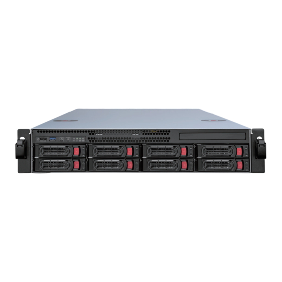
2.1.2 2U (12 / 8-Bay) Models 2.1.2.1 12-Bay Models Figure 2-2 No. Name Name USB 3.1 (Type A) Port x 2 HDD Group A Reset Button HDD Group B Power Button HDD Group C LED Panel HDD Group D (See 2.2 LED Panel View for details.) - Page 19 Overview 2.1.2.2 8-Bay Models HDD 3 HDD 4 HDD 1 HDD 2 HDD 6 HDD 7 HDD 8 HDD 5 Figure 2-3 For details on the other features of the front panel, see Figure 2-1.
-
Page 20: Led Panel View
2.2 LED Panel View A LED panel on the front door provides a quick indication of the activity status of hard disk drives. Note the panel design and function vary from model to model. 2.2.1 4U (20-Bay) / 2U (12 / 8-Bay) Models Figure 2-5 No. -
Page 21: Rear View
Overview 2.3 Rear View Here we use the 4U (20-bay) model of GV-NVRH V6 as an example. Name Power Connector x 1 HDMI x 1 DisplayPort x 1 USB 2.0 (Type-A) x 3 LAN 2.5 GbE (on the left side of the rear panel) x 1... -
Page 22: Chapter 3 Getting Started
Chapter 3 Getting Started Basic Installation Here we use the 2U (8-bay) model as an example. Figure 3-1 1. Connect the keyboard and mouse to any of the USB ports. 2. Connect one end to the AC input and the other end to the power outlet using the supplied power cord. -
Page 23: Turning On The Power
Getting Started Turning on the Power Once the above hardware is properly connected, it is the time to turn on the GV-Hot Swap Surveillance System V6. To turn on the power, follow these steps: 1. Turn on the monitor. Figure 3-2 2. - Page 24 The GV-Hot Swap Surveillance System V6 will run a series of self-tests, and later series of messages may be displayed as the various hardware and software subsystems are activated. After this is finished, ⚫ GV-Hot Swap NVR System pops up GV-IP Device Utility to detect IP devices under the same LAN.
-
Page 25: Installing The Hard Drive
Getting Started Installing the Hard Drive The GV-Hot Swap Surveillance System V6 uses SATA hard drives for video and audio data storage. Before recording, be sure to install your hard drives. IMPORTANT: Be sure to install each of your hard drives separately for formatting. See 3.5 Formatting the Hard Drive for details. -
Page 26: Installing The Sliding Rail Kit
Installing the Sliding Rail Kit The sliding rail kit makes it easy for users to mount the GV-Hot Swap Surveillance System V6 onto the server rack. With its tool-less design, users can easily place the models for a more organized space allocation. - Page 27 Getting Started Align the spring clip on chassis (inner) member of the pre-performed bayonets on both sides of the chassis. Push back the inner member to allow the rail slide to be fixed to the rackmount chassis. Make sure the spring clip installation has been completed on the rackmount chassis when finishing the step.
- Page 28 Insert the stag into the upper and lower square holes on EIA rail from the back of rail. Push the safety lock forward to secure the bracket. Make sure to check if the safety lock is in unlocked position before mounting the brackets.
- Page 29 Getting Started Insert the chassis (inner) member into the cabinet member as shown below. Make sure to check if the ball retainer is in a fully open position before installing the chassis. Release the slide from locking position by pressing the trigger down when pushing the chassis back to the cabinet.
-
Page 30: For 4U 20-Bay Models
3.4.2 For 4U 20-Bay Models Install chassis ear kit onto both sides of the model. Pull out the inner rail of the sliding rail and secure it on both sides of the model. - Page 31 Getting Started Install the sliding rails onto the server rack, and secure the front and rear with screws. Pull out the middle part of the rails, align the inner rails onto the chassis, and slide the chassis into the server tack until the quick-release handle on the ear kit snaps into place with the server rack.
-
Page 32: Windows Setup Installation
Windows Setup Installation The Windows setup is preparing your computer for first use. 1. After the Windows starts, this setup screen appears. Select your language and click Next to continue. Figure 3-7 2. Select your regional settings and time zone and click Next to continue. Figure 3-8... - Page 33 Getting Started 3. Click Accept to accept Microsoft software license terms. 4. Select between “Customize” or “Use Express settings” for your Windows 10 installation. 5. Type your account name. It is recommended that you create a password for your account and click Next.
-
Page 34: Formatting The Hard Drive
Formatting the Hard Drive Be sure to install each of your hard drives separately for formatting. Do not install and format more than one hard drive at a time. Depending on the model of your choices, install and format the hard drives in alphabetical order as indicated below. - Page 35 Getting Started To format a hard disk, follow the steps below: Right-click the Computer icon on your desktop, select Manage, and select Disk Management when the Computer Management window appears. 2. On the main page of Disk Management, the Initialize Disk dialog box appears for the new drive.
- Page 36 The New Simple Volume Wizard appears. Click Next to continue. Figure 3-13 6. The default partition size is the same as the maximum disk space. Make changes if necessary. Click Next to continue. Figure 3-14...
- Page 37 Getting Started 7. Assign a drive path that is not in use by other devices, and click Next to continue. Figure 3-15 Note: The default drive path starts from D:\. 8. Type a name in the Volume label box, ex. HDD1, and click Next to continue. Figure 3-16...
- Page 38 9. When the formatting is complete, click Finish to close the wizard. Figure 3-17 10. When the drive is successfully initialized, partitioned, and formatted, its status description should display “Healthy.” Figure 3-18...
-
Page 39: Setting Up The Video Storage Location
Getting Started Setting Up the Video Storage Location To achieve stable recording performance, you need to divide your hard disks into 4 / 8 storage groups and each group is assigned with an equal number of cameras. Note: Be sure to follow the hard drive installation of 20 / 12 / 8-bay models as below. See 3.5 Formatting the Hard Drive for details. - Page 40 Storage Group 1 Storage Group 2 Storage Group 3 Storage Group 4 2U 12-bay GV-Hot Swap NVR / VMS System 64-channel Camera 01-16 Camera 17-32 Camera 33-48 Camera 49-64 32-channel Camera 01-08 Camera 09-16 Camera 17-24 Camera 25-32 2U 8-bay Storage Group 1 Storage Group 2 Storage Group 3 Storage Group 4 GV-Hot Swap NVR / VMS...
- Page 41 Getting Started Storage arrangement for receiving 256 channels Storage Storage Storage Storage Storage Storage Storage Storage Group 1 Group 2 Group 3 Group 4 Group 5 Group 6 Group 7 Group 8 4U 20-bay Camera Camera Camera Camera Camera Camera Camera Camera 1~128-channel...
- Page 42 To create a storage group for GV-Hot Swap VMS System, 1. On the GV-VMS, open the Recording dialog box (Home > Toolbar > Configure > System Configure > Record Setting). 2. Select a camera and click next to Add Log Location to open the following dialog box. Figure 3-20 3.
- Page 43 Getting Started To create a storage group for GV-Hot Swap NVR System, On the GV-NVR, click the Set Location button and select Storage Group Folder. This dialog box appears. Figure 3-22 To create a storage group, click the Add Storage Group icon The first storage group is created by default.
- Page 44 To create a storage group for GV-Hot Swap Recording Server System, 1. On the GV-Recording Server, click Storage Path under Server. This dialog box appears. Bullet Camera1 Bullet Camera2 Bullet Camera3 Bullet Camera4 Bullet Camera5 Bullet Camera6 Bullet Camera7 Bullet Camera8 Bullet Camera9 Bullet Camera10 Bullet Camera11...
-
Page 45: Setting Up On-Screen Led Panel
Getting Started Setting Up On-Screen LED Panel Note the function is not supported by GV-Hot Swap Recording Server System. For GV-Hot Swap NVR / VMS System, a LED panel on the screen provides a quick indication of the activity status of hard disk drives. Figure 3-24 LED Color Description... - Page 46 2. Click Tools on the menu bar and select Setup LED Panel. This dialog box appears. Figure 3-26 ◼ LED Panel always stays on top: This option makes the LED panel stay on top of other windows when the Media Man Tools window is minimized. ◼...
-
Page 47: Replacing The Hard Drive
Replacing the Hard Drive You can replace the hard drive in the Hot Swap Drive Bay without shutting down the GV-Hot Swap Surveillance System V6. 1. Make sure the HDD Activity LED (No. 2, Figure 2-5) is off. 2. Slide the release latch to the right. The drawer handle pops up. -
Page 48: Configuring The Ip Address
3.10 Configuring the IP Address The GV-Hot Swap Surveillance System V6 supports remote monitoring, control and configuration over a network connection. The following default IP addresses will automatically be assigned. • 192.168.0.200 (All models) • 192.168.0.201 (Only available for GV-Hot Swap NVR / VMS / Recording Server System) •... - Page 49 Getting Started To change the static IP addresses or to enable dynamic IP address, follow the steps below. 1. Right-click the Network Connection icon from the notification area and select Open Network and Sharing Center. Figure 3-28 2. Click Change Adapter Settings from the left-hand side menu of the Network and Sharing Centre window.
- Page 50 5. Select Use the following IP address and type the new IP information in the fields or select Obtain an IP address automatically to enable dynamic IP address. Figure 3-31 6. Click OK to finish the setting. Note: For models with multiple Ethernet ports, it is recommended to assign IP channels received and clients transmitted into different networks.
- Page 51 Getting Started 3.11 Dual View Display 3.11.1 GV-Hot Swap System V6 You can display multiple views on up to 2 monitors simultaneously, one for live viewing and the other for playback or other operation without obstructing surveillance scene, with GV-Hot Swap System V6.
- Page 52 8. Go to the system folder and locate DMPOS.exe. Figure 3-33 9. Run DMPOS.exe. This dialog box appears. Figure 3-34 10. In the Screen Setup tab, select a desired monitor display mode, such as Twin View or Three View, from the Displayer Mode drop-down list. 11.
-
Page 53: Gv-Hot Swap Vms System V6
Getting Started 3.11.2 GV-Hot Swap VMS System V6 You can customize the display settings of GV-VMS. Click Home , select Toolbar select Configure , select System Configure, and click Set Position. This dialog box appears. The right side of the dialog box is only available when multiple monitors are installed. -
Page 54: Digital Matrix
3.12 Digital Matrix Note this function is not available for GV-Hot Swap VMS System V6, GV-Hot Swap Recording Server System. To create more screen space to display multiple channels, such as 32 channels, Digital Matrix is thus introduced to provide a way to view and manage multiple monitor displays. -
Page 55: Setting Live View
Getting Started 3.12.2 Setting Live View You can set different live views and screen divisions for each monitor. 1. On the main screen, click the Configure button, click Accessories, and select Digital Matrix Setting. This dialog box appears. Figure 3-37 2. -
Page 56: Setting Scanned
3.12.3 Setting Scanned Pages You can set up to 16 scanned pages with different screen divisions and channels for each monitor. 1. Use the Display list to select the monitor to be configured. 2. In the upper-left column, expand the Matrix folder tree, and then click Page 1. This page appears. -
Page 57: Setting Pop-Up Alert
Getting Started 3.12.4 Setting Pop-up Alert You can be alerted by pop-up live videos when motion is detected or I/O devices are triggered. 1. Use the Display list to select the monitor to be configured. 2. In the upper-left column, click Event Popup. This page appears. Figure 3-39 ◼... -
Page 58: Setting Pop-Up Positions
3.12.5 Setting Pop-up Positions When you select Random Position of Camera, you can decide the positions for pop-up cameras. ◼ Fixed Position of Camera: The cameras pop up in their assigned positions. To assign positions, select Screen Division. Then drag and drop the cameras number to the desired potions on the divisions. -
Page 59: Setting Live View With Pop-Up Alert
Getting Started 3.12.6 Setting Live View with Pop-up Alert You can set a different live view mode with pop-up alert together for each monitor. When alert events occur, the live video of the associated camera will pop up on the assigned monitor to replace its live view mode. -
Page 60: Extended Installation
3.13 Extended Installation Optionally, you can purchase GV-IO Box series or GV-Keyboard V3 accessories to make your unit even more powerful and convenient, Gigabit Network Cards for additional gigabit ports, and Redundant Power Supply for uninterrupted supply of power. GV-Keyboard V3 ⚫... - Page 61 Getting Started After the System starts up, the Keyboard controller dialog box will automatically appear and start service. The dialog box will run in the background and closing the dialog box will cause GV-Keyboard V3 to disconnect. Figure 3-41...
-
Page 62: I/O Devices
3.13.2 I/O Devices Optionally, you can purchase GV-IO Box series for the connection with external I/O devices. GV-I/O Box series provides a varied number of inputs and relay outputs. It supports both DC and AC output voltages with optional support for Ethernet module and 4E additionally supporting POE connection. -
Page 63: Gigabit Network Cards
The optional Gigabit and 10 Gigabit Network Cards are available for GV-Hot Swap System V6 upon request, with two choices of 1-Gb single port card and 2-port 10-Gb (20 Gb) card. The number of optional Network Cards supported varies with different models. Refer to the table below. -
Page 64: Redundant Power Supply
3.13.4 Redundant Power Supply The Redundant Power Supply comes with 2 power supply modules for 4U models. Each power supply module shares the loading of the power supply. When one of the power supply modules is down, the other module still supports full power for the system. 4U models Figure 3-44 LED Indicators... - Page 65 Getting Started The Audio Alarm When the audio alarm of the Redundant Power Supply rings, check: 1. If the modules are pushed all the way to the end, or 2. The power input is properly connected to the power supply. If the modules are properly installed but the audio alarm continues to ring, the modules may be damaged and you may need to contact your distributor for a replacement.
-
Page 66: System Restoration
3.14 System Restoration You can restore the operating system and system software back-up files using Windows Tool. Refer to the instructions here. -
Page 67: Updating Gv-Hot Swap Surveillance System V6
3.15 Updating GV-Hot Swap Surveillance System V6 GeoVision will periodically update the GV-System Software (Multicam Surveillance System). If you like to update your GV-Hot Swap Surveillance System V6, contact your dealer for more information or check software update news at our website:... -
Page 68: Chapter 4 Troubleshooting
A portable 2.5'' HDD connected to the front panel cannot be detected. When the portable 2.5” HDD connected to a GV-Hot Swap Surveillance System V6 cannot be detected, try this step: Use a dual head USB cable and insert both heads to the USB ports on the GV-Hot Swap Surveillance System V6 front panel as illustrated below. - Page 69 Figure 4-2 2. Make sure that the power cord is properly connected to both GV-Hot Swap Surveillance System V6 and power outlet. If you are using a power strip, make sure that the strip is powered on. 3. If the problem persists, consult your dealer.
- Page 70 GV-Hot Swap Surveillance System V6’s hard disk corrupts. If you are experiencing file system corruption problems, such as lost clusters, cross-linked files or invalid files or directories, try these steps: 1. Use the HD Tune utility to scan the hard disk for errors. Follow these steps: A.
- Page 71 Troubleshooting 2. If the HD Tune utility does not find any defects, use the Windows built-in utility to attempt to fix the errors. Follow these steps: A. Right-click the Computer icon on your desktop, select Manage, and select Disk Management when the Computer Management window appears. B.
- Page 72 If your GV-Hot Swap Surveillance System V6 suffers virus attack, try rebuilding the operating system and the software. Refer to 3.13 System Restoration.
-
Page 73: Specifications
14.47 Note: 1. The data for GV-VMSH / NVRH V6 was determined using the bit rate listed above and hard disks with average R/W speed above 110 MB/s. The H.265 codec is only supported by GV-VMS V15.11.0.0 or later and GV-DVR /... - Page 74 Specification RAID Group Requirements For ensuring high performance of RAID group deployment, the maximum number of recording channel that you can assign to a single RAID 5 group is suggested as below. Video Resolution Frame Rate (fps) Max. Channel 1.3 MP 50 (6.16 Mbps) 2 MP 32 (12.59 Mbps)
-
Page 75: Appendix
Appendix A. Supported IP Devices This list provides the supported IP device brands. For detailed information on the supported IP devices, refer to Supported IP Camera List on GeoVision’s Website: http://www.geovision.com.tw/ GeoVision ACTi Arecont Vision AXIS Bosch Canon D-Link Etrovision... -
Page 76: Assigning Network Cards
Appendix B. Assigning Network Cards GV-NVRH V6 / GV-VMSH V6 and GV-Hot Swap Recording Server System come with multiple Ethernet ports. To increase network bandwidth and avoid network bottleneck, you need to set up multiple networks and divide networks into different multiple subnets or segments. Next, organize IP channels received and clients transmitted into different networks. - Page 77 For GV-VMSH V6, the recommended network allocation is illustrated as below. The first network card can receive up to 64 IP channels in 2 M resolution. The second network card can transmit up to 64 channels in 2 M resolution.
-
Page 78: Warranty Requirements
Appendix Warranty Requirements Thank you for purchasing the GV-Hot Swap Surveillance System V6. GeoVision understands that accidents happen, and have developed a warranty policy in place. See http://www.geovision.com.tw/warranty.php for more information on warranty. Before you return the product Some problems you experience may be related to software or the operating system. It is important to investigate other sources of assistance first. - Page 79 2. Securely pack the product in its original carton using the original packing material, or in equivalent packaging. 3. The product shall be returned to GeoVision, Taiwan at your expense for shipping and insurance costs. BEFORE YOU DELIVER YOUR GV-HOT SWAP SURVEILLANCE SYSTEM V6 FOR WARRANTY SERVICE, IT IS YOUR RESPONSIBILITY TO BACK UP YOUR DATA.
Need help?
Do you have a question about the V6 and is the answer not in the manual?
Questions and answers