GeoVision GV-SNVR0400F User Manual
Hide thumbs
Also See for GV-SNVR0400F:
- User manual (136 pages) ,
- Quick start manual (54 pages) ,
- Quick start manual (25 pages)
Table of Contents
Advertisement
Quick Links
Advertisement
Table of Contents

Related Manuals for GeoVision GV-SNVR0400F


Summary of Contents for GeoVision GV-SNVR0400F
- Page 1 GV-SNVR User’s Manual User’s Manual SNVR-UM-A...
- Page 2 GeoVision. Every effort has been made to ensure that the information in this manual is accurate. GeoVision, Inc. makes no expressed or implied warranty of any kind and assumes no responsibility for errors or omissions. No liability is assumed for incidental or consequential damages arising from the use of the information or products contained herein.
-
Page 3: Table Of Contents
1.6.1 Front View ....................5 1.6.2 Rear View....................7 Chapter 2 Getting Started ..................9 2.1 Installing the Hard Drive ..................9 2.1.1 GV-SNVR0400F ..................9 2.1.2 GV-SNVR1600 ..................11 2.2 Interface Connections ..................13 2.2.1 Network Connection for GV-SNVR1600 ............ 14 2.3 Initial Configuration.................... - Page 4 3.4 Storage......................... 33 3.5 System ......................... 34 Chapter 4 Video Playback ..................37 4.1 Timeline Player..................... 37 4.2 Recording Backup....................39 Chapter 5 Remote Access to the GV-SNVR............40 5.1 Accessing the Surveillance Images through Web Browser ........40 5.1.1 Live View Screen..................42 5.1.2 Snapshot of Live Video................
-
Page 5: Chapter 1 Introduction
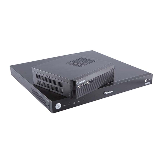
Introduction Chapter 1 Introduction The GV-SNVR0400F / GV-SNVR1600 is a Linux-embedded Standalone Network Video Recorder which records video files directly to the internal hard drive, supporting up to 4 / 16 channels of GV-IP Cameras for network surveillance. With the feature of a Full HD HDMI video output, the GV-SNVR eliminates the need for a separate PC to view and play back video from the unit. -
Page 6: Feature
․ PTZ control using GV-Joystick V2 or on-screen panel ․ 1080p HDMI video output ․ 1 SATA HDD drawer (3.5”) for up to 4 TB storage (for GV-SNVR0400F) ․ 4 SATA HDD drawer (3.5”) for up to 16 TB storage (for GV-SNVR1600) ․... -
Page 7: Packing List
5. Rack Mount Kit (2 L-shaped brackets and 6 screws included) 1.4 Compatible Devices and System Requirements 1.4.1 Supported GV-IP Cameras The GV-SNVR0400F / 1600 is compatible with the following GV-IP Cameras: ․ GV-Target Series IP Camera (Firmware V1.0 or later) ․ GV-SD220/220-S (Firmware V1.04 or later) ․... -
Page 8: System Requirement
1.4.2 System Requirements Recommended Hard Disks GV-SNVR0400F supports 1 SATA HDD (3.5”) with up to 4 TB capacities, and GV-SNVR1600 supports 4 SATA HDD (3.5”) with total up to 16 TB capacities. For system efficiency, it is recommended to use the enterprise-level hard disk drives instead of desktop-level or green HDD. -
Page 9: Overview
Introduction 1.6 Overview 1.6.1 Front View 1.6.1.1 GV-SNVR0400F 1 2 3 Figure 1-2 No. Name Function USB 2.0 Port Connects to keyboard, mouse, storage device or GV-Joystick V2. Audio In Not functional. Audio Out Not functional. Power LED Shows constant blue when the power is supplied for the device. - Page 10 1.6.1.2 GV-SNVR1600 Figure 1-3 No. Name Function Power Button Turns on/off the power. Power LED Shows constant blue when the power is supplied for the device. HDD Status LED Glows blue when the hard drive is writing or reading data. Shows constant red when the following situations occur: ․...
-
Page 11: Rear View
Introduction 1.6.2 Rear View 1.6.2.1 GV-SNVR0400F Figure 1-4 No. Name Function Gigabit Ethernet Port Connects to t he network. HDMI Output Connects to the HD TV. Connects to keyboard, mouse, storage device or GV-Joystick USB 2.0 Port Rest ores the device to default settings. Press the button for 15 Default Button seconds to load default. - Page 12 1.6.2.2 GV-SNVR1600 Figure 1-5 N o. Name Function Audio Microphone In Port Not functional. VGA Monitor Output Connects to the VGA mo nitor. HDMI Port Connects to the HD TV. Connects to keyb oard, mouse, storage device or USB 2.0 Port x 4 GV-Joystick V2.
-
Page 13: Chapter 2 Getting Started
The GV-SNVR uses SATA hard drive for video data storage. Before recording, be sure to install the hard drive. 2.1.1 GV-SNVR0400F Follow the steps below to install the hard drive to the GV-SNVR0400F. 1. Unscrew the two screws on the rear panel and remove the cover. Figure 2-1 2. - Page 14 3. Place the hard drive in the drive drawer as below by aligning the three holes. Figure 2-3 4. Secure the hard drive with the drive drawer using the supplied 6 screws (3 screws on each side). Figure 2-4 5. Connect the SATA Power Cable and Data Cable to the hard drive. SATA Power Cable Data Cable...
-
Page 15: Gv-Snvr1600
Getting Started 2.1.2 GV-SNVR1600 Follow the steps below to install the hard drive to the GV-SNVR1600. 1. Loosen the 6 screws and remove the cover. Figure 2-6 2. Assemble the mounting brackets with the hard drive and tighten the screws on both sides. Figure 2-7 Note: Each mounting bracket is labeled L or R for recognition. - Page 16 4. Tighten the 4 screws on the side of the hard drive. Front Rear Panel Panel Side View of the HDD Figure 2-9 5. Connect the SATA Power Cable and Data Cable to the hard drive. SATA Power Cable Data Cable Figure 2-10 6.
-
Page 17: Interface Connections
Getting Started 2.2 Interface Connections Follow the steps below to connect the GV-SNVR. GV-SNVR1600 GV-SNVR0400F Figure 2-11 1. Connect the GV-SNVR to power. 2. Connect the GV-SNVR to the LAN port using the RJ-45 cable. 3. For GV-SNVR1600, connect speakers to the Audio Line Out port. -
Page 18: Network Connection For Gv-Snvr1600
Note: The GV-SNVR is DHCP enabled. When it is connected to the network, it will be automatically assinged an IP address. For GV-SNVR1600, the monitor used for VGA output must be capable of having a screen resolution of 1080p. 2.2.1 Network Connection for GV-SNVR1600 There are two network ports, LAN and WAN, for the GV-SNVR1600. -
Page 19: Initial Configuration
Getting Started 2.3 Initial Configuration After you have installed the IP cameras under the same LAN with the GV-SNVR, you are ready to display the channels on GV-SNVR. 2.3.1 Automatically setting up GV-IP Camera To automatically set up the IP cameras, follow the steps below. Power on the GV-SNVR. - Page 20 IMPORTANT: By default, GV-IP Cameras have the IP address 192.168.0.10. The GV-SNVR will automatically assign unused IP addresses to these cameras to avoid IP address conflict with others under the same LAN. The GV-SNVR connects with IP cameras with the default ID and password admin. If you fail to log in the IP camera, click the Edit icon and type the correct ID and password for connection.
-
Page 21: Manually Connecting Gv-Ip Camera
Getting Started 2.3.2 Manually Connecting GV-IP Camera To manually add the GV-IP Camera to the camera list, follow the steps below. On the Camera page, click the Add Cameras button. Type the IP Address, Username and Password of the desired IP camera. Keep the default Port 10000 or modify if necessary. -
Page 22: Changing Cameras And Assigning Channels
2.3.3 Changing Cameras and Assigning Channels On the Camera page, you can change the connected IP cameras and re-assign the channels for display. For example, to change the camera on Channel 1, deselect the connected camera on Channel 1 and select another camera for connection. The selected camera is now assigned to Channel 1. -
Page 23: Formatting The Hard Drive
Getting Started 2.4 Formatting the Hard Drive After installing the hard drive to GV-SNVR, you need to format the hard drive before enabling the monitoring. On the main screen, click the Setting button. Figure 2-18 Select Storage. Figure 2-19 Click Format. This dialog box appears. Figure 2-20 Click Execute to format the hard drive. - Page 24 When the hard drive is successfully formatted, its icon should be marked with a green tick, and the “Normal” message appears. The information of operating temperature, hard drive status and total time in use is also displayed. Operating Time in Use Temperature HDD Status Figure 2-21...
-
Page 25: Main Screen
Getting Started 2.5 Main Screen Close the Camera page to display connected channels on the main screen. Here we use GV-SNVR0400F for illustration. Figure 2-22 No. Name Description Indicates the camera name. The column changes from gray to red Camera Name when the recording is enabled. -
Page 26: Enabling The Recording
2.6 Enabling the Recording To start recording, click the Record button (No. 4, Figure 2-22) and select a camera. To enable recording for all the connected cameras, select Start All Monitoring. By default, the GV-SNVR records with the Round-the-clock mode and H.264 codec. The default recording resolution depends on the settings of each camera. -
Page 27: Live Monitoring
Getting Started 2.8 Live Monitoring GV-SNVR0400F On the main screen, the live view of connected cameras is displayed in 4 divisions by default. You can click the Division button (No. 5, Figure 2-22) and select 1 or 4 Division. Optionally, click on the live view of desired camera to switch to full screen. -
Page 28: Audio
2.8.2 Audio To enable the audio function on live video, follow the steps below. Note: The audio function is only available for GV-SNVR1600. To listen to the audio, make sure the Enable Audio function is applied for the camera. For details, see 3.1 Camera. Click the live view of the desired camera to switch to full screen. -
Page 29: Ptz Control
Getting Started 2.8.3 PTZ Control To enable the PTZ function on live video, click the camera name of desired camera and select Enable PTZ. The PTZ control panel appears at the lower-right corner of the live view. Note: The option is only available for the cameras supporting PTZ functions. Tilt Focus Control... - Page 30 For details on the GV-Joystick V2, see GV-Joystick V2 User’s Manual. Note: The GV-SNVR does not support GV-Keyboard. Digital PTZ Function For non-PTZ cameras, the Digital PTZ (DPTZ) function allows you to simulate the PTZ movement on the screen. Note: The DPTZ function is only available for GV-SNVR1600. To enable the DPTZ function on live video, click the camera name of desired camera and select Enable Digital PTZ.
-
Page 31: Chapter 3 System Configuration
System Configuration Chapter 3 System Configuration This section introduces the settings of camera, video recording, network, storage and system. Camera To access the camera settings, click the Edit button of desired camera on the Camera page. Figure 3-1 The Camera Settings page appears. Figure 3-2... - Page 32 Codec: The video codec is H.264. Resolution: Select the video resolution for the camera. FPS: Set up recording frame rate for the camera. Note the GV-SNVR0400F / 1600 supports up to 30 fps. Quality: Select the level of video quality.
-
Page 33: Recording
System Configuration Recording You can set up desired recording mode for specific period on specific days for each connected camera. The default recording mode is round-the-clock. Figure 3-3 1. Select a camera from the drop-down list at the upper-right corner. 2. -
Page 34: Network
Network The Network section includes basic network configurations that enable the GV-SNVR to be connected to the network. By default, the GV-SNVR is assigned with a dynamic IP address when connecting to the network. [LAN] Figure 3-4 IP Configuration: Select DHCP or Static according to your network environment. MAC Address: Displays the MAC Address of the GV-SNVR. - Page 35 System Configuration [WAN] Figure 3-5 IP Configuration: Select DHCP or Static according to your network environment. MAC Address: Displays the MAC Address of the GV-SNVR. To enable the PPPoE connection, select PPPoE and fill out the required settings below. Primary DNS: Type a primary DNS. The default is 192.168.100.1. Second DNS: Type a second DNS.
- Page 36 DDNS function, you should have applied for a Host Name from the DDNS service provider’s website. The provider is GeoVision DDNS Server, http://ns.gvdip.com/register.aspx. Figure 3-5 To enable the DDNS function, click the Enable box, type the hostname and password you have registered with GeoVision DDNS Server and click Apply.
-
Page 37: Storage
System Configuration [E-mail] Configure your mail server to allow e-mail notification on: ․ Recording error of writing recording data to the hard disk drive ․ Request for retrieving the username and password for system login Figure 3-6 Sender: Type the sender’s e-mail address. Receiver: Type the recipients’... -
Page 38: System
System On the System page, you can access the configuration of login information of Administrator and Guest, video resolution and time settings. You can also access the system log with filter as desired. Figure 3-7 [System] Device Name: Type a desired name for the GV-SNVR. Language: Select English, Traditional Chinese, Spanish, Russian, Portuguese, French, German, Italian or Japanese as the language of the OSD interface. - Page 39 System Configuration Default Camera Password: Set up the default password of camera for connection. The default is admin. Temperature: Select a temperature scale for the display of operating temperature. Resolution: Select the video output resolution from 720p, 1080p and 1080i. Note: The Resolution options are not available for GV-SNVR1600, which only supports the resolution of 1080p.
- Page 40 Date Format Setup: Select a desired format for date display. To enable the settings, click Apply. Note: You can also use the GV-IP Device Utility to synchronize the date and time of GV-SNVR with a computer. For details, see GV-IP Device Utility Installation Guide on the Software CD.
-
Page 41: Chapter 4 Video Playback
Without further settings you can play back the video recording by selecting desired time period and clicking the Play button on Playback Panel. To switch the current view mode, click the Division button. Here we use GV-SNVR0400F for illustration. Figure 4-1... - Page 42 Playback Panel Contains typical playback control buttons. Live Closes the timeline player and returns to live view window. For GV-SNVR0400F, switches between 1-channel and Division 4-channel view; for GV-SNVR1600, switches between 1-channel, 4-channel, 9-channel and 16-channel view. Exports the video recording as AVI files to an external hard Export drive.
-
Page 43: Recording Backup
The video recording is exported to the external hard drive. The backup recordings are in AVI format. To play back the recordings using Windows Media Player, you need to install GeoVision codec in the dedicated PC. Otherwise you can install the GV-ViewLog player for playback. -
Page 44: Chapter 5 Remote Access To The Gv-Snvr
Browser To access the live view through Web interface, follow the steps below. Here we use the GV-SNVR0400F for illustration. 1. Open your Web browser and type the IP address of the GV-SNVR. Note: To look up the IP address of GV-SNVR, see 3.3 Network. Optionally, run the GV-IP Device Utility to search for your GV-SNVR. - Page 45 After the installation, live view will be displayed. Note: 1. The maximum number of remote network connection is 10 in total for GV-SNVR0400F and 34 in total for GV-SNVR1600. Every connected channel will be counted as 1 connection.
-
Page 46: Live View Screen
5.1.1 Live View Screen After successfully logging in the Web interface, you can access the live view of connected IP cameras. Figure 5-2 No. Name Description Division & Page Selects screen divisions and switch between cameras in single Up / Down division. - Page 47 Device Name Recognizes the device name. Note: 1. For all GV-IP Cameras, the Web interface of GV-SNVR0400F / 1600 supports main stream for the display of full screen only. For details, see Appendix B Live View Streaming. 2. The Visual Automation function is not supported.
-
Page 48: Snapshot Of Live Video
5.1.2 Snapshot of Live Video To take a snapshot of live video, follow the steps below. 1. Right-click on the live view of desired camera and select Snapshot. The Save As dialog box appears. Figure 5-3 2. Select a desired saving path, type the file name and select JPEG or BMP as the Save as Type. -
Page 49: Picture-In-Picture View
Remote Access to the GV-SNVR 5.1.3 Picture-in-Picture View With the Picture in Picture (PIP) view, you can crop the video to get a close-up view or zoom in on the video. This function is useful for detailed images of the surveillance area. 1. -
Page 50: Picture-And-Picture View
5.1.4 Picture-and-Picture View With the Picture and Picture (PAP) view, you can create a split video effect with multiple close-up views on the image. Up to 7 close-up views can be defined for clear and detailed images of the surveillance area. 1. -
Page 51: Digital Ptz Control
Remote Access to the GV-SNVR 5.1.5 Digital PTZ Control In non-PTZ cameras, the Digital PTZ (DPTZ) function allows you to simulate the PTZ movement on the screen. This function is also supported in PT / PTZ cameras. Note: The Digital PTZ function is not supported in the 16-division display. 1. -
Page 52: Accessing The Surveillance Images Through Smart Device
Accessing the Surveillance Images through Smart Device To access the live view of GV-SNVR through the iOS or Android devices, you must install your smart devices with GV-Eye. With GV-Eye, you can watch multiple live view in dual streams, enable the Picture in Picture (PIP) function and take snapshots from your mobile device. -
Page 53: Chapter 6 Advanced Applications
Remote Access to the GV-SNVR Chapter 6 Advanced Applications 6.1 Upgrading System Firmware GeoVision periodically release the updated firmware on the Website. You can upgrade the firmware using an USB storage drive of FAT32 format. To upgrade the firmware, follow the steps below. -
Page 54: Using The Gv-Ip Device Utility
6.2 Using the GV-IP Device Utility The GV-IP Device Utility detects all the GV-IP Devices in the LAN and allows you to quickly set up the IP address of the device, upgrade firmware and export/import device settings. For details, see GV-IP Device Utility Installation Guide on the Software CD. 6.2.1 Looking up the IP Address You can use the GV-IP Device Utility to look up the IP address of your GV-SNVR and GV-IP Camera. -
Page 55: Upgrading System Firmware
Remote Access to the GV-SNVR 6.2.3 Upgrading System Firmware You can also use the GV-IP Device Utility to upgrade firmware of multiple GV-SNVR at the same time. Note the computer used to upgrade firmware must be under the same LAN with the GV-SNVR. -
Page 56: Backing Up And Restoring Settings
4. If you like to upgrade all the GV-SNVR in the list, select Upgrade all devices. 5. Type Password, and click Upgrade to start the upgrade. 6.2.4 Backing up and Restoring Settings With the GV-IP Device Utility, you can back up the configurations in the GV-SNVR and restore the backup data to the current GV-SNVR or import it to another one. - Page 57 Remote Access to the GV-SNVR To restore the settings: 1. In Figure 6-5, click the Import Settings tab. This dialog box appears. Figure 6-6 2. Click the Browse button to locate the backup file (.dat). 3. Select Upgrade all devices to import the settings into all the GV-SNVR under the same LAN.
-
Page 58: Specifications
Specifications Hardware Model GV-SNVR0400F GV-SNVR1600 System 1 GB 512 MB Embedded Linux No. of Drive Bay 1 (3.5” HDD) 4 (3.5” HDD) Input: AC 100 ~ 230V, Input: AC 100 ~ 230V, 50 ~ 60 Hz Power Source 50 ~ 60 Hz Output: DC 19V, 3.42A,... - Page 59 Specifications Model GV-SNVR0400F GV-SNVR1600 Video and Audio Audio Compression G.711 Audio Support Two-Way Audio Operation Max. 50 Mbps for 4 Max. 100 Mbps for 16 Recording Bandwidth channels channels Recording Mode Round the clock / Motion Detection / Schedule Recording Pre Recording 1 ~ 10 sec.
-
Page 60: Appendix
Appendix A. Tested and Supported Hard Disk Drives For system efficiency, it is recommended to use the enterprise-level hard disk drives instead of desktop-level or green HDD. The HDD listed below are tested by GeoVision. Model Capacity WD4000F9YZ 4 TB... -
Page 61: Live View Streaming
4 TB HUS724020ALA640 2 TB B. Live View Streaming The default streaming for local display, Web browser and smart device access are listed below. Screen Display GV-SNVR0400F GV-SNVR1600 1 Division Stream 1 Stream 1 4 Divisions Stream 1 Stream 1...
Need help?
Do you have a question about the GV-SNVR0400F and is the answer not in the manual?
Questions and answers