
Related Manuals for GeoVision GV-AS4111


Summary of Contents for GeoVision GV-AS4111
- Page 1 GV-AS4111/8111 Kit User’s Manual Before attempting to connect or operate this product, please read these instructions carefully and save this manual for future use. AS4111.8111_UL_B...
- Page 2 Every effort has been made to ensure that the information in this manual is accurate. GeoVision, Inc. makes no expressed or implied warranty of any kind and assumes no responsibility for errors or omissions. No liability is assumed for incidental or consequential damages arising from the use of the information or products contained herein.
-
Page 3: Table Of Contents
4 GV-AS4111 / 8111 Kit..................17 4.1 Packing List ....................17 4.2 GV-AS4111 / 8111 Kit Overview ..............18 4.3 GV-AS4111 / 8111 Kit Standard Application ...........19 4.4 Connecting the GV-AS4111 / 8111 Kit ............20 4.5 GV-AS4111 / 8111 Kit Specifications ..............22 5 The Web Interface .................... -
Page 4: Compatible Devices
GV-AS4111 / 8111 Kit is a cabinet containing a GV-AS4111 or GV-AS 8111, a power adapter board, a power supply and a casing for backup GV-AS4111 / 8111 Kit battery. The power supply provides power to GV-AS4111 / 8111 and up to 8 output devices (12V, 0.5A per device). -
Page 5: Installation Considerations
Through network connection, up to 1000 GV-AS Controllers can connect to GV- ASManager. Note: For GV-AS4111 / 8111, it is highly recommended to replace the button cell battery included on the circuit board annually. All control units shall be mounted in a protected area. -
Page 6: Definition
Definition Tampering Alarm To enable tampering alarm, install the sensor separately. The triggering conditions depend on the type of sensor installed. The GV-AS Controller also provides output relays for activating and deactivating electric lock, siren and emergency door release when tampering is detected by the sensors. -
Page 7: Introduction
1 Introduction 1.1 Main Features GV-AS4111 • One-way control: 4 doors • Two-way control: 4 doors by Wiegand / RS-485 / Network • Support 8 Wiegand card readers of 26 to 64 bits • Support 8 GV-Readers through RS-485 connection / Network •... -
Page 8: Packing List
1.2 Packing List GV-AS4111 • Power Adapter (12V DC, 3.5A) • Power Cord • Battery Cable • Screw x 8 • Hex Nut x 8 • Hex Pillar x 8 • Micro SD Card 2 GB • Software CD •... - Page 9 1.3 GV-AS4111 / 8111 Board Layout OUT11 OUT12 OUT13 OUT14 OUT15 OUT16 OUT10 Micro SD OUT9 Ethernet OUT17 OUT20 OUT21 OUT24 OUT8 RTC Battery IN16 IN15 OUT18 OUT19 OUT22 OUT23 OUT7 IN14 IN13 IN12 OUT6 IN11 Reset IN10 OUT5 IN09...
-
Page 10: Installation
RS-485: Only compatible with all GV-Readers. 2.1.1 Wiegand Readers GV-AS4111 / 8111 provides 8 Wiegand inputs (Wiegand A to Wiegand H). Connect up to 8 Wiegand readers ranging from 26 to 64 bits to the Wiegand interfaces. Please consult the documentation of your Wiegand reader for wiring. -
Page 11: Rs-485 Readers
Use 12V power output and GND on the power terminal or the Wiegand connectors to power on each unit. Terminal Resistor B+ B- Not functional for GV-AS4111 kit RS485 12V OUTPUT Connect each reader to the power terminal or Wiegand... - Page 12 By default, a jumper cap is installed on the RS485_A Terminal Resister (J37) to ensure stability when the RS-485 connection between GV-AS4111 / 8111 and the reader is 600 meters. Although up to 8 RS-485 readers can be connected, GV-AS4111 only supports control of up to 4 doors.
-
Page 13: Connecting Input Devices
2.2 Connecting Input Devices Up to 16 input devices can be connected to GV-AS4111 / 8111. Connect the input wires to IN1~16 and connect GND wires to GND. Multiple GND wires can be connected to the same GND pin. All inputs are dry contact that can be configured as normally open (NO) or normally closed (NC) on the Web interface. -
Page 14: Connecting Output Devices
(+) point on the power supply to the NO or NC of GV-AS4111 / 8111 based on the state of the output device. There are two ways to supply power to the output device: ... -
Page 15: Connecting Backup Battery
2.4 Connecting Backup Battery You can connect any 12V battery to GV-AS4111 / 8111 to provide backup power when the main power supply fails. When the main power supply is removed and the battery voltage level is above 10.2V, the Discharging LED will light and the battery will support normal operation of the GV-AS4111 / 8111. -
Page 16: Connecting The Pc
2.6 Connecting the PC Connecting GV-AS4111 / 8111 to a computer allows you to access its Web interface and connect it to GV-ASManager if the computer is installed with GV-ASManager. The computer running GV-ASManager software can be used to monitor the access information and alarm messages from GV-AS4111 / 8111. - Page 17 Note: GV-AS4111 / 8111 is only compatible with GV-ASManager V4.2.3 or later. Data processing equipment and office appliance and business equipment used as computer equipment shall comply with the Standard for Information Technology Equipment - Safety - Part 1: General Requirements, UL 60950-1.
-
Page 18: Other Settings
(BAT) Web Setting Switch Figure 9 3.2 Resetting the GV-AS4111 / 8111 To reset GV-AS4111 / 8111, press the Reset button on the right side of GV-AS4111 / 8111 circuit board for three seconds. Ethernet OUT21 OUT24 NO COM NC... -
Page 19: Restoring Factory Defaults
3.3 Restoring Factory Defaults To restore GV-AS4111 / 8111 to factory default settings, press the Default button for 10 seconds. Load Default Button CON11 CON12 Figure 11... -
Page 20: Gv-As4111 / 8111 Kit
4 GV-AS4111 / 8111 Kit GV-AS4111 / 8111 Kit is a cabinet containing a GV-AS4111 or GV-AS 8111, a power adapter board, a power supply and a casing for backup battery. The power supply provides power to GV-AS4111 / 8111 and up to 8 output devices (12V, 0.5A per device). -
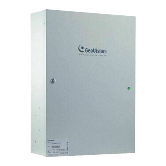
Page 21: Gv-As4111 / 8111 Kit Overview
4.2 GV-AS4111 / 8111 Kit Overview GV-AS4111 GV-AS8111 Power Adapter Board Casing for Backup Battery Power Supply Figure 12... -
Page 22: Gv-As4111 / 8111 Kit Standard Application
4.3 GV-AS4111 / 8111 Kit Standard Application Output Power Source Limitation Output 1 ~ 24 Class 2 External Output Power Con 10 ~ Con 11 Class 2 Device Supply Class 2 Con 9 Class 2 J8 ~ J11 (Power board) -
Page 23: Connecting The Gv-As4111 / 8111 Kit
Up to 8 output devices can be powered by the power adapter board. Connect each output device to one terminal block on the board. Connect the COM pin on GV-AS4111 / 8111’s output terminal block to the corresponding pin on the power adapter board. Connect the NC / NO pins according to the state of the output device. - Page 24 Note: The power supply of GV-AS4111 / 8111 Kit comes in US standard, UL standard, and EU standard. Make sure the device is connected with a voltage within its voltage range. You can place a backup battery in the supplied battery casing, and connect the backup battery to the GV-AS4111 / 8111 board.
-
Page 25: Gv-As4111 / 8111 Kit Specifications
4.5 GV-AS4111 / 8111 Kit Specifications Power Adapter Board DC Voltage Range Output Rated Current 0.5A Rated Power Input Number of connectors Output Wire Size (AWG) 12 ~ 22 Power Supply DC Voltage Range 11V ~ 13V (Nominal 12V) Output... -
Page 26: The Web Interface
5 The Web Interface You can install GV-AS4111 / 8111 on a network and configure GV-AS4111 / 8111 through its Web interface. -
Page 27: Gv-As4111 / 8111 Specifications
8 Wiegand interfaces, 26 ~ 64 bit format, distance 100 m Wiegand Interface (328.1ft), 24 AWG, 13V DC min., 85 °C min. TCP/IP Interface 1 TCP/IP interface for GeoVision network readers Communication Protocol TCP/IP Battery Built-in battery, replaceable button cell (CR2032) - Page 28 Weight 900 g / 2 lb Certification UL, CE, FCC, RoHS Note: The system is evaluated for the following performance levels: Type of Approval Feature Level Destructive Attack Line Security Endurance Standby Power All specifications are subject to change without notice.
Need help?
Do you have a question about the GV-AS4111 and is the answer not in the manual?
Questions and answers