Table of Contents
Advertisement
Quick Links
TANK -720 E mbedded S ys tem
MODE L :
TA NK -720
High P erformanc e F anles s E mbedded S ys tem with
2nd G en Intel® C ore™ i7/i5/i3, C eleron® and P entium® des ktop proc es s ors ,
On-board 2.0 G B DDR 3 Memory, V G A/HDMI, US B 3.0, Dual C ombo (S F P
F iber/R J -45) G igabit L AN, Is olated C AN-bus , A udio and R oHS C ompliant
Us er Manual
P age i
R ev. 2.02 – 7 Marc h 2018
Advertisement
Table of Contents

Related Manuals for IEI Technology TANK-720


Summary of Contents for IEI Technology TANK-720
- Page 1 TANK -720 E mbedded S ys tem MODE L : TA NK -720 High P erformanc e F anles s E mbedded S ys tem with 2nd G en Intel® C ore™ i7/i5/i3, C eleron® and P entium® des ktop proc es s ors , On-board 2.0 G B DDR 3 Memory, V G A/HDMI, US B 3.0, Dual C ombo (S F P F iber/R J -45) G igabit L AN, Is olated C AN-bus , A udio and R oHS C ompliant Us er Manual...
- Page 2 Update Section 3.2: Hard Disk Drive (HDD) Installation 20 February 2013 1.03 Update Section 3.9.11: Remote Control Terminal Block 21 June 2012 1.02 Update the system memory capacity 12 March 2012 1.01 Update the pictures for TANK-720 25 October 2011 1.00 Initial release P age ii...
- Page 3 TANK -720 E mbedded S ys tem C opyright C OP Y R IG HT NOT IC E The information in this document is subject to change without prior notice in order to improve reliability, design and function and does not represent a commitment on the part of the manufacturer.
- Page 4 TANK -720 E mbedded S ys tem W AR NING This device complies with Part 15 of the FCC Rules. Operation is subject to the following two conditions: (1) this device may not cause harmful interference, and(2) this device must accept any interference received, including interference that may cause undesired operation.
- Page 5 TANK -720 E mbedded S ys tem Manual C onventions WAR NING Warnings appear where overlooked details may cause damage to the equipment or result in personal injury. Warnings should be taken seriously. C AUT ION Cautionary messages should be heeded to help reduce the chance of losing data or damaging the product.
-
Page 6: Table Of Contents
TANK -720 E mbedded S ys tem Table of C ontents 1 INTRODUCTION ......................1 1.1 O ........................2 VERVIEW 1.2 M ..................... 2 ODEL ARIATIONS 1.3 F ........................3 EATURES 1.4 T ..................3 ECHNICAL PECIFICATIONS 1.5 C ..................... 5 ONNECTOR ANEL 1.5.1 Front Panel ...................... - Page 7 TANK -720 E mbedded S ys tem 3.9.5 CAN-bus Terminal Block .................. 27 3.9.6 Digital I/O Connector ..................28 3.9.7 HDMI Connector ..................... 28 3.9.8 LAN Connectors ....................29 3.9.9 Power Input, 4-pin Terminal Block ..............31 3.9.10 Power Input, 4-pin DIN Connector ............... 31 3.9.11 Remote Control Terminal Block (For AT Power Mode Only) ......
- Page 8 TANK -720 E mbedded S ys tem 4.3.3 CPU Configuration ..................55 4.3.3.1 CPU Information ..................56 4.3.4 SATA Configuration ..................57 4.3.5 USB Configuration ................... 59 4.3.6 Secondary Super IO Configuration ..............61 4.3.6.1 Serial Port n Configuration ..............61 4.3.7 Super IO Configuration ...................
- Page 9 TANK -720 E mbedded S ys tem E HAZARDOUS MATERIALS DISCLOSURE ............103 P age ix...
- Page 10 TANK -720 E mbedded S ys tem L is t of F igures Figure 1-1: TANK-720 ........................2 Figure 1-2: TANK-720 Front Panel ....................6 Figure 1-3: TANK-720 Rear Panel ....................7 Figure 1-4: TANK-720 LED Indicators ................... 8 Figure 1-5: Physical Dimensions (mm) ..................9 Figure 3-1: Bottom Panel Retention Screws ................17...
- Page 11 TANK -720 E mbedded S ys tem Figure 3-26: RJ-45 RS-422/485 Serial Port Pinout Location .............36 Figure 3-27: DB-9 Connector Pinout Location ................36 Figure 3-28: Serial Device Connector ..................37 Figure 3-29: Serial Port Pinout Location ..................38 Figure 3-30: USB Device Connection ..................39 Figure 3-31: VGA Connector .......................40 Figure 3-32: VGA Connector .......................40 Figure 3-33: Power Button ......................41...
- Page 12 TANK -720 E mbedded S ys tem L is t of Tables Table 1-1: TANK-720 Model Variations ..................2 Table 1-2: Technical Specifications ....................5 Table 3-1: Digital I/O Connector Pinouts ..................28 Table 3-2: HDMI Connector Pinouts ...................29 Table 3-3: LAN Pinouts ........................30 Table 3-4: RJ-45 Ethernet Connector LEDs ................31...
- Page 13 BIOS Menu 17: Northbridge Chipset Configuration ..............75 BIOS Menu 18: Graphics Configuration ..................75 BIOS Menu 19: Southbridge Chipset Configuration ..............77 BIOS Menu 20: ME Configuration ....................79 BIOS Menu 21: Boot ........................80 BIOS Menu 22: Security .......................83 BIOS Menu 23:Exit ........................84 TANK-720 P age xiii...
-
Page 14: Introduction
TANK -720 E mbedded S ys tem C hapter Introduc tion P age 1... -
Page 15: Overview
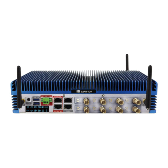
1.1 Overview Figure 1-1: TANK-720 The TANK-720 Series fanless embedded system is powered by the 2nd Generation Intel® Core™ i7/i5/i3 and Pentium®/Celeron® desktop processor, uses the Intel® Q67 chipset and has 2.0 GB of DDR3 memory. It supports dual display via VGA and HDMI. Two SATA 6Gb/s, two USB 3.0 and four USB 2.0 ports provide flexible expansion options. -
Page 16: Features
Redundant dual DC power input (10V~36V) CAN-bus interface with isolation 1.4 Tec hnic al S pecifications The TANK-720 technical specifications are listed in Table 1-2. S pec ific ations S ys tem 2nd Generation Intel® Core™ i7/i5/i3 and Pentium®/Celeron® C P U desktop processor Intel®... - Page 17 TANK -720 E mbedded S ys tem S pec ific ations I/O and Indic ators 2 x Combo (SFP Fiber/RJ-45) Gigabit LAN E thernet 4 x DB-9 serial ports on rear panel R S -232 2 x RJ-45 serial ports with isolation on front panel 2 x RJ-45 serial ports with isolation on front panel R S -422/R S -485 2 x USB 3.0 ports on front panel...
-
Page 18: Connector Panel
P hys ic al Dimens ions Table 1-2: Technical Specifications 1.5 C onnec tor P anel 1.5.1 F ront P anel The TANK-720 front panel contains: 2 x 4-channel audio/video input (Optional) 1 x CAN-bus terminal block with isolation ... -
Page 19: Rear Panel
TANK -720 E mbedded S ys tem 2 x Wi-Fi antenna connectors An overview of the front panel is shown in Figure 1-2. Figure 1-2: TANK-720 Front Panel 1.5.2 R ear P anel The TANK-720 rear panel contains: 1 x DIO port ... -
Page 20: Figure 1-3: Tank-720 Rear Panel
2 x SFP Fiber combo Gigabit LAN ports 4 x USB 2.0 ports 1 x VGA port 1 x Wi-Fi antenna connector An overview of the rear panel is shown in Figure 1-3 below. Figure 1-3: TANK-720 Rear Panel P age 7... -
Page 21: Led Indicators
LED indicator lights up. Refer to Section 1.6 for the locations of the LED indicators. 1.6 L E D Indic ators There are several indicators on the front panel of the TANK-720 as shown in Figure 1-4. Figure 1-4: TANK-720 LED Indicators WAR NING : The CPU Temperature Alert LED turns red when the CPU temperature is too high. -
Page 22: Dimensions
TANK -720 E mbedded S ys tem 1.7 Dimens ions The physical dimensions are shown below: Figure 1-5: Physical Dimensions (mm) P age 9... -
Page 23: Unpacking
TANK -720 E mbedded S ys tem C hapter Unpac king P age 10... -
Page 24: Anti - Static Precautions
When the TANK-720 is unpacked, please do the following: Follow the anti-static precautions outlined in Section 2.1. Make sure the packing box is facing upwards so the TANK-720 does not fall out of the box. Make sure all the components shown in Section 2.3 are present. -
Page 25: Unpacking Checklist
If some of the components listed in the checklist below are missing, please do not proceed with the installation. Contact the IEI reseller or vendor you purchased the TANK-720 from or contact an IEI sales representative directly. To contact an IEI sales representative, please send an email to sales@iei.com.tw. - Page 26 TANK -720 E mbedded S ys tem Quantity Item and P art Number Image S tandard Chassis screw (P/N: 44013-030041-RS) RJ-45 to DB-9 COM port cable (P/N: 32005-000200-200-RS) Wi-Fi antenna (for Wi-Fi module only) (P/N: 32505-000900-100-RS) Pluggable DC-in terminal block (P/N: 33502-000055-RS) Pluggable CAN-bus terminal block (P/N: 33502-000007-RS)
- Page 27 Gigabit Ethernet SFP module (P/N: SFP1G-SX/-I SFP1G-MLX/-I SFP1G-LX10/-I SFP1G-ZX70/-I) Fiber cord (P/N: FPC-LCLC-MM3M FPC-LCLC-SS3M) OS: Win CE 6.0 (CDROM) (P/N: TANK-720-Q67-CE060-R10) OS: Win XPE (CDROM) (P/N: TANK-720-Q67-XPE-R10) OS: Linux (CDROM) (P/N: TANK-720-Q67-LNX-R10) OS: Win 7 Embedded (CDROM) (P/N: TANK-720-Q67-WES7E-R10) P age 14...
-
Page 28: Installation
TANK -720 E mbedded S ys tem C hapter Ins tallation P age 15... -
Page 29: Installation Precautions
Electric shock and personal injury might occur if the rear panel of the TANK-720 is opened while the power cord is still connected to an electrical outlet. -
Page 30: Figure 3-1: Bottom Panel Retention Screws
Remove the four HDD bracket retention screws and unplug the SATA signal and S tep 2: power cables connected to the TANK-720. And then lift the HDD bracket out of the TANK-720 and put it on a flat surface. Figure 3-2: HDD Bracket Retention Screws... -
Page 31: Figure 3-3: Hdd Installation
S tep 4: Secure each HDD with the HDD bracket by four retention screws (eight in all). Figure 3-4: HDD Retention Screws Secure the HDD bracket with TANK-720 by the four retention screws that were S tep 5: previously removed. -
Page 32: Pluggable Can- Bus Terminal Block Installation
TANK -720 E mbedded S ys tem Reconnect the SATA signal and power cables to the TANK-720. S tep 6: Reinstall the bottom panel to the TANK-720. S tep 7: 3.3 P luggable C AN-bus Terminal B loc k Ins tallation To install the pluggable CAN-bus terminal block, please follow the steps below: Locate the CAN-bus terminal block connector. -
Page 33: Pluggable Remote Control Terminal Block Installation
Figure 1-3. Align the pluggable remote control terminal block with the remote control S tep 2: terminal block connector on the TANK-720. Once aligned, insert the pluggable remote control terminal block into the remote S tep 3: control terminal block connector. -
Page 34: Sfp Module Installation
Locate the SFP fiber connectors. The locations of the connectors are shown in S tep 1: Figure 1-3. Align the SFP module with one of the SFP fiber connectors on the TANK-720 S tep 2: (Figure 3-8). Once aligned, slide the SFP module into place (Figure 3-8). -
Page 35: So-Dimm Installation
Remove the bottom panel by removing the five retention screws from the bottom S tep 1: panel (Figure 3-1). Unplug the SATA signal and power cables connected to the TANK-720, and then S tep 2: place the bottom panel on a flat surface. -
Page 36: Mounting The System With Mounting Brackets
Install the bracket that was previously removed in the same position it was S tep 8: before. Reinstall the bottom panel to the TANK-720. S tep 9: 3.8 Mounting the S ys tem with Mounting B rac kets To mount the embedded system onto a wall or some other surface using the two mounting brackets, please follow the steps below. -
Page 37: External Peripheral Interface Connectors
Insert four retention screws, two in each bracket, to secure the system to the S tep 6: wall. 3.9 E xternal P eripheral Interfac e C onnec tors The TANK-720 has the following connectors. Detailed descriptions of the connectors can be found in the subsections below. ACC mode switch ... -
Page 38: Acc Mode Switch
3.9.1 AC C Mode S witc h The TANK-720 allows turning the ACC mode on or off. The setting can be made through the ACC mode switch on the rear panel as shown below. Figure 3-12: ACC Mode Switch 3.9.2 AT /AT X P ower Mode S witc h... -
Page 39: Figure 3-13: At/Atx Power Mode Switch
TANK -720 E mbedded S ys tem Figure 3-13: AT/ATX Power Mode Switch P age 26... -
Page 40: Audio Connector
Figure 3-14: Audio Connector 3.9.4 Audio/Video Input C onnec tors The TANK-720 can support up to eight video inputs and eight audio inputs through the BNC and RCA connectors on the front panel. The locations of the connectors are shown in Figure 1-2. -
Page 41: Digital I/O Connector
TANK -720 E mbedded S ys tem 3.9.6 Digital I/O C onnec tor DIO x 8 C N L abel: DB-9 male connector C N T ype: See Figure 1-3 C N L oc ation: See Table 3-1 and Figure 3-16 C N P inouts : The digital I/O connector provides programmable input and output for external devices. -
Page 42: Lan Connectors
Locate the RJ-45 connectors. The locations of the RJ-45 connectors are S tep 1: shown in Figure 1-3. Align the connectors. Align the RJ-45 connector on the LAN cable with one of S tep 2: the RJ-45 connectors on the TANK-720. See Figure 3-17. P age 29... -
Page 43: Figure 3-17: Lan Connection
TANK -720 E mbedded S ys tem Figure 3-17: LAN Connection Insert the LAN cable RJ-45 connector. Once aligned, gently insert the LAN S tep 3: cable RJ-45 connector into the on-board RJ-45 connector. Description Description TRD1P0 TRD1P2 TRD1N0 TRD1N2 TRD1P1 TRD1P3 TRD1N1... -
Page 44: Power Input, 4-Pin Terminal Block
TANK -720 E mbedded S ys tem Activity/Link LED Speed LED DESCRIPTION STATUS DESCRIPTION STATUS No link 10 Mbps connection Yellow Linked Green 100 Mbps connection Blinking TX/RX activity Orange 1 Gbps connection Table 3-4: RJ-45 Ethernet Connector LEDs 3.9.9 P ower Input, 4-pin Terminal B loc k C N L abel: POWER 1 4-pin terminal block... -
Page 45: Remote Control Terminal Block (For At Power Mode Only)
TANK -720 E mbedded S ys tem The power connector connects to the 10.5V~36V DC power adapter. Figure 3-20: Power Input Connector Description Description +12V +12V Table 3-6: Power Input Pinouts 3.9.11 R emote C ontrol Terminal B loc k (F or AT P ower Mode Only) Remoter C N L abel: 2-pin terminal block... -
Page 46: Rs-232 Serial Port Connectors
Figure 1-2. S tep 2: Insert the RJ-45 connector. Insert the RJ-45 connector on the RJ-45 to DB-9 COM port cable to one of the RJ-45 RS-232 connectors on the TANK-720. See Figure 3-22. Figure 3-22: RJ-45 RS-232 Serial Device Connection Insert the serial connector. -
Page 47: Figure 3-23: Rj-45 Rs-232 Serial Port Pinout Location
TANK -720 E mbedded S ys tem Figure 3-23: RJ-45 RS-232 Serial Port Pinout Location Description Description Table 3-7: RJ-45 RS-232 Serial Port Pinouts Figure 3-24: DB-9 Connector Pinout Location Description Description Table 3-8: DB-9 Connector Pinouts P age 34... -
Page 48: Rs-422/485 Serial Port Connectors
RS-422/485 connectors are shown in Figure 1-2. S tep 2: Insert the RJ-45 connector. Insert the RJ-45 connector on the RJ-45 to DB-9 COM port cable to one of the RJ-45 RS-422/485 connectors on the TANK-720. See Figure 3-25. Figure 3-25: RJ-45 RS-422/485 Serial Device Connection Insert the serial connector. -
Page 49: Figure 3-26: Rj-45 Rs-422/485 Serial Port Pinout Location
TANK -720 E mbedded S ys tem Figure 3-26: RJ-45 RS-422/485 Serial Port Pinout Location Description Description TXD485# RXD485# TXD485+ RXD485+ Table 3-9: RJ-45 RS-422/485 Serial Port Pinouts Figure 3-27: DB-9 Connector Pinout Location Description (RS-422) Description (RS-485) RXD422+ RXD422# TXD422+ TXD485+ TXD422#... -
Page 50: Serial Port Connectors
TANK -720 E mbedded S ys tem 3.9.14 R S -232 S erial P ort C onnec tors COM1, COM2, COM3 and COM4 C N L abel: DB-9 connectors C N T ype: See Figure 1-3 C N L oc ation: See Table 3-11 and Figure 3-29 C N P inouts : RS-232 serial port devices can be attached to the RS-232 serial ports on the rear panel. -
Page 51: Sfp Fiber Connectors
Figure 3-29: Serial Port Pinout Location 3.9.15 S F P F iber C onnec tors The TANK-720 has two SFP fiber connectors. The locations of the connectors are shown in Figure 1-3. To install an SFP module, refer to Section 3.6. -
Page 52: Vga Connector
TANK -720 E mbedded S ys tem Figure 3-30: USB Device Connection Insert the device connector. Once aligned, gently insert the USB device S tep 3: connector into the USB connector on the TANK-720. Description Description DATA- DATA- DATA+ DATA+... -
Page 53: Figure 3-31: Vga Connector
Insert the VGA connector. Once the connectors are properly aligned with, S tep 3: insert the male connector from the VGA screen cable into the female connector on the TANK-720. See Figure 3-31. Figure 3-31: VGA Connector S tep 4: Secure the connector. -
Page 54: Powering O N /Off The System
TANK -720 E mbedded S ys tem Description Description GREEN BLUE VCC / NC DDC DAT HSYNC VSYNC DDCCLK Table 3-13: VGA Connector Pinouts P owering On/Off the S ys tem 3.10 WARNING: Make sure a power supply with the correct input voltage is being fed into the system. -
Page 55: Redundant Power
TANK -720 E mbedded S ys tem 3.11 R edundant P ower The TANK-720 is a system that supports redundant power. The redundant power input increases the reliability of the system and prevents data loss and system corruption from sudden power failure. The system can instantly and uninterruptedly switch to the second power input when the main power is unavailable or in low voltage capacity. -
Page 56: Acc On
The ACC On mode is designed for vehicle applications. When the TANK-720 is in ACC On mode, the main power input is Power 1 connector and the backup power is from Power 2 connector. -
Page 57: Switch To Backup Power
TANK -720 E mbedded S ys tem 3.11.1.2 S witc h to B ac kup P ower During the operation, the system power will switch from Power 1 to Power 2 automatically when the following situations occur: Power 1 < 10V and Power 2 > 10.5V ... -
Page 58: Acc Off
Press the Power button for six seconds to turn off the system. 3.11.2 AC C OF F When the TANK-720 is in ACC Off mode, the main power input is Power 2 connector and the backup power is from Power 1 connector. 3.11.2.1 B oot-up When both power connectors are connected to a power source with over 9 V, the two power LEDs on the front panel turn on. -
Page 59: Switch To Backup Power
TANK -720 E mbedded S ys tem 3.11.2.2 S witc h to B ac kup P ower During the operation, the system power will switch from Power 2 to Power 1 automatically when the following situations occur: Power 2 < 10.5V and Power 1 > 10V ... - Page 60 TANK -720 E mbedded S ys tem NOTE: The power LED turns off when the power cable is unplugged from the system. P age 47...
-
Page 61: Bios
TANK -720 E mbedded S ys tem C hapter B IOS P age 48... -
Page 62: Introduction
TANK -720 E mbedded S ys tem 4.1 Introduc tion The BIOS is programmed onto the BIOS chip. The BIOS setup program allows changes to certain system settings. This chapter outlines the options that can be changed. 4.1.1 S tarting S etup The UEFI BIOS is activated when the computer is turned on. -
Page 63: Getting Help
TANK -720 E mbedded S ys tem K ey F unc tion Previous values Load optimized defaults Save changes and Exit BIOS Table 4-1: BIOS Navigation Keys 4.1.3 G etting Help When F1 is pressed a small help window describing the appropriate keys to use and the possible selections for the highlighted item appears. -
Page 64: Main
TANK -720 E mbedded S ys tem 4.2 Main The Main BIOS menu (BIOS Menu 1) appears when the BIOS Setup program is entered. The Main menu gives an overview of the basic system information. Aptio Setup Utility – Copyright (C) 2011 American Megatrends, Inc. Main Advanced Chipset... -
Page 65: Advanced
TANK -720 E mbedded S ys tem iW DD Vers ion The iWDD Version displays the current iWDD version. The fields in iWDD Version cannot be changed. Memory Information The Memory Information lists a brief summary of the on-board memory. The fields in Memory Information cannot be changed. -
Page 66: Acpi Settings
TANK -720 E mbedded S ys tem Aptio Setup Utility – Copyright (C) 2011 American Megatrends, Inc. Main Advanced Chipset Boot Security Save & Exit > ACPI Settings System ACPI Parameters > Trusted Computing > CPU Configuration > SATA Configuration >... -
Page 67: Trusted Computing
TANK -720 E mbedded S ys tem AC P I S leep S tate [S 1 (C P U S top C loc k)] Use the ACPI Sleep State option to specify the sleep state the system enters when it is not being used. -
Page 68: Cpu Configuration
TANK -720 E mbedded S ys tem T P M S upport [Dis able] Use the TPM Support option to configure support for the TPM. Disable TPM support is disabled. EFAULT Enable TPM support is enabled. 4.3.3 C P U C onfiguration Use the CPU Configuration menu (BIOS Menu 5) to view detailed CPU specifications and configure the CPU. -
Page 69: Cpu Information
TANK -720 E mbedded S ys tem Intel Virtualization Tec hnology [Dis abled] Use the Intel Virtualization Technology option to enable or disable virtualization on the system. When combined with third party software, Intel Virtualization technology allows several OSs to run on the same system at the same time. ... -
Page 70: Sata Configuration
SATA Mode [IDE Mode] Serial-ATA Controller 0 [Compatible] --------------------- SATA Port0 Not Present : Select Screen SATA Port1 IEI Technology (15.4G ↑ ↓: Select Item Enter Select Change Opt. General Help Previous Values Optimized Defaults Save & Exit Exit Version 2.11.1210. Copyright (C) 2011 American Megatrends, Inc. - Page 71 TANK -720 E mbedded S ys tem Disable Disables SATA devices. IDE Mode Configures SATA devices as normal IDE device. EFAULT RAID Mode Configures SATA devices as RAID device. S erial-ATA C ontroller 0 [C ompatible] Use the Serial-ATA Controller 0 option to configure the Serial-ATA controller mode when the SATA mode is set to IDE Mode.
-
Page 72: Usb Configuration
TANK -720 E mbedded S ys tem 4.3.5 US B C onfiguration Use the USB Configuration menu (BIOS Menu 8) to read USB configuration information and configure the USB settings. Aptio Setup Utility – Copyright (C) 2011 American Megatrends, Inc. Advanced USB Configuration USB Support Parameters... - Page 73 TANK -720 E mbedded S ys tem L egac y US B 3.0 S upport [E nabled] Use the USB3.0 Support option to enable or disable USB 3.0 support on the system. Enabled USB 3.0 support enabled EFAULT ...
-
Page 74: Secondary Super Io Configuration
TANK -720 E mbedded S ys tem 4.3.6 S ec ondary S uper IO C onfiguration Use the Secondary Super IO Configuration menu (BIOS Menu 9) to set or change the configurations for the serial ports. Aptio Setup Utility – Copyright (C) 2011 American Megatrends, Inc. Advanced Secondary Super IO Configuration Set Parameters of Serial... - Page 75 TANK -720 E mbedded S ys tem 4.3.6.1.1 S erial P ort 7 C onfiguration S erial P ort [E nabled] Use the Serial Port option to enable or disable the serial port. Disabled Disable the serial port ...
- Page 76 TANK -720 E mbedded S ys tem Disabled Disable the serial port Enabled Enable the serial port EFAULT C hange S ettings [Auto] Use the Change Settings option to change the serial port IO port address and interrupt address.
-
Page 77: Super Io Configuration
TANK -720 E mbedded S ys tem 4.3.7 S uper IO C onfiguration Use the Super IO Configuration menu (BIOS Menu 11) to set or change the configurations for the serial ports. Aptio Setup Utility – Copyright (C) 2011 American Megatrends, Inc. Advanced Super IO Configuration Set Parameters of Serial... - Page 78 TANK -720 E mbedded S ys tem 4.3.7.1.1 S erial P ort 1 C onfiguration S erial P ort [E nabled] Use the Serial Port option to enable or disable the serial port. Disabled Disable the serial port ...
- Page 79 TANK -720 E mbedded S ys tem Enabled Enable the serial port EFAULT C hange S ettings [Auto] Use the Change Settings option to change the serial port IO port address and interrupt address. Auto The serial port IO port address and interrupt address EFAULT are automatically detected.
- Page 80 TANK -720 E mbedded S ys tem Auto The serial port IO port address and interrupt address EFAULT are automatically detected. IO=3E8h; Serial Port I/O port address is 3E8h and the interrupt IRQ=10 address is IRQ10 IO=3E8h; Serial Port I/O port address is 3E8h and the interrupt IRQ=10, 11 address is IRQ10, 11...
- Page 81 TANK -720 E mbedded S ys tem IO=2E8h; Serial Port I/O port address is 2E8h and the interrupt IRQ=10, 11 address is IRQ10, 11 IO=2D0h; Serial Port I/O port address is 2D0h and the interrupt IRQ=10, 11 address is IRQ10, 11 ...
- Page 82 TANK -720 E mbedded S ys tem IO=2E0h; Serial Port I/O port address is 2E0h and the interrupt IRQ=10, 11 address is IRQ10, 11 Devic e Mode [R S 422/485] Use the Device Mode option to set the serial port to normal or RS-422/485 communications..
-
Page 83: H/W Monitor
TANK -720 E mbedded S ys tem IO=2D0h; Serial Port I/O port address is 2D0h and the interrupt IRQ=10, 11 address is IRQ10, 11 IO=2D8h; Serial Port I/O port address is 2D8h and the interrupt IRQ=10, 11 address is IRQ10, 11 ... -
Page 84: Serial Port Console Redirection
TANK -720 E mbedded S ys tem P C Health S tatus The following system parameters and values are shown. The system parameters that are monitored are: System Temperatures: CPU Temperature System Temperature Voltages: V3.3S CPU_CORE +V5S +V12S +1.5V_DDR3 VSB3V... -
Page 85: Bios Menu 14: Serial Port Console Redirection
TANK -720 E mbedded S ys tem Aptio Setup Utility – Copyright (C) 2011 American Megatrends, Inc. Advanced COM1 Console Redirection Console Redirection [Disabled] Enable or Disable > Console Redirection Settings COM2 Console Redirection [Disabled] > Console Redirection Settings COM3 Console Redirection [Disabled] >... -
Page 86: Iei Feature
TANK -720 E mbedded S ys tem 4.3.10 iE i F eature Use the iEi Feature menu (BIOS Menu 15) to configure the iEi features. Aptio Setup Utility – Copyright (C) 2011 American Megatrends, Inc. Advanced iEi Feature Auto Recovery Function Reboot and recover Auto Recovery Function [Disabled]... -
Page 87: Chipset
TANK -720 E mbedded S ys tem 4.4 C hips et Use the Chipset menu (BIOS Menu 16) to access the Northbridge and Southbridge configuration menus. WAR NING ! Setting the wrong values for the Chipset BIOS selections in the Chipset BIOS menu may cause the system to malfunction. -
Page 88: North Bridge
TANK -720 E mbedded S ys tem 4.4.1 North B ridge Use the North Bridge menu (BIOS Menu 17) to configure the Northbridge chipset. Aptio Setup Utility – Copyright (C) 2011 American Megatrends, Inc. Chipset Memory Information Config Graphics Settings. Total Memory 2048 MB (DDR3 1333) Memory Slot... -
Page 89: South Bridge
TANK -720 E mbedded S ys tem Use the DVMT Mode Select option to select the Intel Dynamic Video Memory Technology (DVMT) operating mode. Fixed Mode A fixed portion of graphics memory is reserved as graphics memory. DVMT Mode Graphics memory is dynamically allocated according to EFAULT the system and graphics needs. -
Page 90: Bios Menu 19: Southbridge Chipset Configuration
TANK -720 E mbedded S ys tem Aptio Setup Utility – Copyright (C) 2011 American Megatrends, Inc. Chipset Auto Power Button Status [OFF] Enabled or Disabled USB Controller USB Controller [Enabled] USB3.0 Controller [Enabled] --------------------- Lan PXE boot Configuration : Select Screen Intel 82583V PXE Boot [Disabled] ↑... - Page 91 TANK -720 E mbedded S ys tem Disabled Disables Intel 82583V PXE Boot option EFAULT Enabled Enables Intel 82583V PXE Boot option Intel 82579L M P XE B oot [Dis abled] Use the Intel 82579LM PXE Boot option to enable or disable the boot option for the Intel 82579LM PXE.
-
Page 92: Me Configuration
TANK -720 E mbedded S ys tem Wake on G be L AN [E nabled] Use the Wake on Gbe LAN option to enable or disable wake on Gbe LAN. Disabled Disables wake on Gbe LAN Enabled Enables wake on Gbe LAN EFAULT R es tore AC P ower L os s [L as t S tate]... -
Page 93: Boot
TANK -720 E mbedded S ys tem ME B x Mode [Normal] Use the MEBx Mode option to configure MEBx Mode options. Normal Enables normal mode EFAULT Hidden Enables hidden Ctrl+P function Ctrl + P Enter Enables user to enter MEBx setup MEBx Setup... - Page 94 TANK -720 E mbedded S ys tem B ootup NumL oc k S tate [On] Use the Bootup NumLock State BIOS option to specify if the number lock setting must be modified during boot up. Allows the Number Lock on the keyboard to be EFAULT enabled automatically when the computer system boots up.
-
Page 95: Security
TANK -720 E mbedded S ys tem Interrupt 19 C apture [Dis abled] Use the Interrupt 19 Capture option to s enable or disable interrupt 19 capture. Force Enables interrupt 19 capture. EFAULT BIOS Keep Disables interrupt 19 capture. Current B oot Option #1 [S ATA S M: IE I Tec h…] ... -
Page 96: Bios Menu 22: Security
TANK -720 E mbedded S ys tem Aptio Setup Utility – Copyright (C) 2011 American Megatrends, Inc. Main Advanced Chipset Boot Security Save & Exit Password Description Set Setup Administrator Password If ONLY the Administrator’s password is set, then this only limits access to Setup and is only asked for when entering Setup. -
Page 97: Exit
TANK -720 E mbedded S ys tem 4.7 E xit Use the Exit menu (BIOS Menu 23) to load default BIOS values, optimal failsafe values and to save configuration changes. Aptio Setup Utility – Copyright (C) 2011 American Megatrends, Inc. Main Advanced Chipset... - Page 98 TANK -720 E mbedded S ys tem S ave as Us er Defaults Use the Save as User Defaults option to save the changes done so far as user defaults. R es tore Us er Defaults Use the Restore User Defaults option to restore the user defaults to all the setup options. P age 85...
-
Page 99: A Regulatory Compliance
TANK -720 E mbedded S ys tem Appendix R egulatory C omplianc e P age 86... - Page 100 TANK -720 E mbedded S ys tem DE C L AR AT ION OF C ONF OR MIT Y This equipment is in conformity with the following EU directives: EMC Directive (2004/108/EC, 2014/30/EU) Low-Voltage Directive (2006/95/EC, 2014/35/EU) RoHS II Directive (2011/65/EU, 2015/863/EU) ...
- Page 101 TANK -720 E mbedded S ys tem Deutsch [German] IEI Integration Corp, erklärt dieses Gerät entspricht den grundlegenden Anforderungen und den weiteren entsprechenden Vorgaben der Richtlinie 2014/53/EU. Eesti [Estonian] IEI Integration Corp deklareerib seadme seadme vastavust direktiivi 2014/53/EÜ põhinõuetele ja nimetatud direktiivist tulenevatele teistele asjakohastele sätetele.
- Page 102 TANK -720 E mbedded S ys tem Lietuvių [Lithuanian] IEI Integration Corp deklaruoja, kad šis įranga atitinka esminius reikalavimus ir kitas 2014/53/EU Direktyvos nuostatas. Nederlands [Dutch] IEI Integration Corp dat het toestel toestel in overeenstemming is met de essentiële eisen en de andere relevante bepalingen van richtlijn 2014/53/EU.
- Page 103 TANK -720 E mbedded S ys tem Slovensko [Slovenian] IEI Integration Corp izjavlja, da je ta opreme v skladu z bistvenimi zahtevami in ostalimi relevantnimi določili direktive 2014/53/EU. Slovensky [Slovak] IEI Integration Corp týmto vyhlasuje, že zariadenia spĺňa základné požiadavky a všetky príslušné ustanovenia Smernice 2014/53/EU. Suomi [Finnish] IEI Integration Corp vakuuttaa täten että...
- Page 104 TANK -720 E mbedded S ys tem Federal Communication Commission Interference Statement This equipment has been assembled with components that comply with the limits for a Class B digital device, pursuant to Part 15 of the FCC Rules. These limits are designed to provide reasonable protection against harmful interference in a residential installation.
-
Page 105: B Bios Options
TANK -720 E mbedded S ys tem Appendix B IOS Options P age 92... - Page 106 TANK -720 E mbedded S ys tem Below is a list of BIOS configuration options in the BIOS chapter. System Overview .........................51 iWDD Vendor ........................51 iWDD Version ........................52 Memory Information ......................52 System Date [xx/xx/xx] ......................52 System Time [xx:xx:xx] .......................52 ...
- Page 107 TANK -720 E mbedded S ys tem Serial Port [Enabled] ......................69 Change Settings [Auto] .......................69 Device Mode [RS422/485] ....................70 PC Health Status ........................71 Console Redirection [Disabled] ..................72 Auto Recovery Function [Disabled] ...................73 DVMT Mode Select [DVMT Mode] ..................75 ...
-
Page 108: C Safety Precautions
TANK -720 E mbedded S ys tem Appendix S afety P rec autions P age 95... -
Page 109: General Safety Precautions
The precautions outlined in this appendix should be strictly followed. Failure to follow these precautions may result in permanent damage to the TANK-720. Please follow the safety precautions outlined in the sections that follow: C .1.1 G eneral S afety P rec autions Please ensure the following safety precautions are adhered to at all times. -
Page 110: Anti-Static Precautions
Electrostatic discharge (ESD) can cause serious damage to electronic components, including the TANK-720. Dry climates are especially susceptible to ESD. It is therefore critical that whenever the TANK-720 is opened and any of the electrical components are handled, the following anti-static precautions are strictly adhered to. -
Page 111: Product Disposal
When maintaining or cleaning the TANK-720, please follow the guidelines below. C .2.1 Maintenanc e and C leaning Prior to cleaning any part or component of the TANK-720, please read the details below. The interior of the TANK-720 does not require cleaning. Keep fluids away ... -
Page 112: Cleaning Tools
In such case, the product will be explicitly mentioned in the cleaning tips. Below is a list of items to use when cleaning the TANK-720. C loth – Although paper towels or tissues can be used, a soft, clean piece of ... -
Page 113: D Digital I/O Interface
TANK -720 E mbedded S ys tem Appendix Digital I/O Interfac e P age 100... -
Page 114: Introduction
TANK -720 E mbedded S ys tem D.1 Introduc tion The DIO connector on the TANK-720 is interfaced to GPIO ports on the Super I/O chipset. The DIO has both 4-bit digital inputs and 4-bit digital outputs. The digital inputs and digital outputs are generally control signals that control the on/off circuit of external devices or TTL devices. -
Page 115: Assembly Language Sample
TANK -720 E mbedded S ys tem D.2 As s embly L anguage S ample 1 AX, 6F08H ;setting the digital port as input AL low byte = value AH – 6FH Sub-function: AL – 9 :Set the digital port as OUTPUT :Digital I/O input value D.3 As s embly L anguage S ample 2 AX, 6F09H... - Page 116 TANK -720 E mbedded S ys tem Appendix Hazardous Materials Dis c los ure P age 103...
- Page 117 TANK -720 E mbedded S ys tem The details provided in this appendix are to ensure that the product is compliant with the Peoples Republic of China (China) RoHS standards. The table below acknowledges the presences of small quantities of certain materials in the product, and is applicable to China RoHS only.
- Page 118 TANK -720 E mbedded S ys tem 此附件旨在确保本产品符合中国 RoHS 标准。以下表格标示此产品中某有毒物质的含量符 合中国 RoHS 标准规定的限量要求。 本产品上会附有”环境友好使用期限”的标签,此期限是估算这些物质”不会有泄漏或突变”的 年限。本产品可能包含有较短的环境友好使用期限的可替换元件,像是电池或灯管,这些元 件将会单独标示出来。 部件名称 有毒有害物质或元素 铅 汞 镉 六价铬 多溴联苯 多溴二苯 醚 (P b) (Hg) (C d) (C R (V I)) (P B B ) (P B DE ) 壳体...
Need help?
Do you have a question about the TANK-720 and is the answer not in the manual?
Questions and answers