Table of Contents
Advertisement
Quick Links
Advertisement
Table of Contents

Subscribe to Our Youtube Channel
Related Manuals for IEI Technology TANK-620-ULT3


Summary of Contents for IEI Technology TANK-620-ULT3
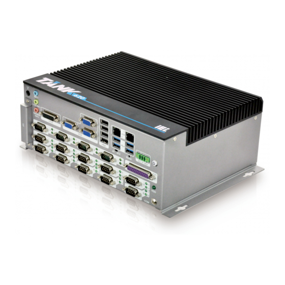
- Page 1 TANK-620-ULT3 Embedded System MODEL: TANK-620-ULT3 Embedded System with Intel® Celeron® 3855U processor, on-board DDR4 4GB Pre-installed Memory, VGA, Two Gigabit Ethernet, RS-232/422/485, RoHS Compliant User Manual Page I Rev. 1.00 – December 26, 2018...
- Page 2 TANK-620-ULT3 Embedded System Revision Date Version Changes December 26, 2018 1.00 Initial release Page II...
- Page 3 TANK-620-ULT3 Embedded System Copyright COPYRIGHT NOTICE The information in this document is subject to change without prior notice in order to improve reliability, design and function and does not represent a commitment on the part of the manufacturer. In no event will the manufacturer be liable for direct, indirect, special, incidental, or consequential damages arising out of the use or inability to use the product or documentation, even if advised of the possibility of such damages.
- Page 4 TANK-620-ULT3 Embedded System Manual Conventions WARNING Warnings appear where overlooked details may cause damage to the equipment or result in personal injury. Warnings should be taken seriously. CAUTION Cautionary messages should be heeded to help reduce the chance of losing data or damaging the product.
-
Page 5: Table Of Contents
TANK-620-ULT3 Embedded System Table of Contents 1 INTRODUCTION ......................1 1.1 O ........................2 VERVIEW 1.2 F ........................2 EATURES 1.3 T ..................3 ECHNICAL PECIFICATIONS 1.4 F ......................5 RONT ANEL 1.5 R ........................ 5 ANEL 1.6 P ....................7... - Page 6 TANK-620-ULT3 Embedded System 4.2 I ................. 25 NTERNAL ERIPHERAL ONNECTORS 4.2.1 Battery Connector (BAT1) ................25 4.2.2 BIOS Programming Connector (JSPI1) ............26 4.2.3 CPU Fan Connector (CPU/FAN1) ..............26 4.2.4 LPT Connector (LPT1) ..................26 4.2.5 EC Debug Connector (CN1) ................27 4.2.6 EC Programming Connector (JSPI2) ..............
- Page 7 TANK-620-ULT3 Embedded System 5.3.2 ACPI Settings ....................43 5.3.3 F81866 Super IO Configuration ..............44 5.3.3.1 Serial Port n Configuration ..............44 5.3.3.2 Parallel Port Configuration ..............48 5.3.4 Hardware Monitor ................... 50 5.3.4.1 Smart Fan Mode Configuration ..............51 5.3.5 F81866SEC Super IO Configuration ...............
- Page 8 TANK-620-ULT3 Embedded System D.1.3 Product Disposal ..................... 99 D.2 M ............99 AINTENANCE AND LEANING RECAUTIONS D.2.1 Maintenance and Cleaning ................100 D.2.2 Cleaning Tools ....................100 E DIGITAL I/O INTERFACE ..................101 E.1 I ....................... 102 NTRODUCTION E.2 A 1 ................
- Page 9 TANK-620-ULT3 Embedded System List of Figures Figure 1-1: TANK-620-ULT3 ......................2 Figure 1-2: TANK-620-ULT3 Front Panel ..................5 Figure 1-3: TANK-620-ULT3 Rear Panel ..................5 Figure 1-4: TANK-870AI slot Physical Dimensions (millimeters) ..........7 Figure 3-1: HDD Panel Retention Screws .................. 14 Figure 3-2: HDD Bracket Retention Screws ................
- Page 10 TANK-620-ULT3 Embedded System List of Tables Table 1-1: Technical Specifications ....................4 Table 3-1: RJ-45 Ethernet Connector LEDs ................18 Table 4-1: Peripheral Interface Connectors ................25 Table 4-2: Battery Connector Pinouts (BAT1) ................25 Table 4-3: BIOS Programming Connector Pinouts (JSPI1) ............26 Table 4-4: CPU Fan Connector Pinouts (CPU/FAN1) ..............
- Page 11 TANK-620-ULT3 Embedded System BIOS Menus BIOS Menu 1: Main ........................40 BIOS Menu 2: Advanced ......................42 BIOS Menu 3: Trusted Computing ....................42 BIOS Menu 4: ACPI Configuration ....................43 BIOS Menu 5: F81866 Super IO Configuration ................44 BIOS Menu 6: Serial Port n Configuration Menu ...............
-
Page 12: Introduction
TANK-620-ULT3 Embedded System Chapter Introduction Page 1... -
Page 13: Overview
SDRAM SO-DIMM modules up to 32 GB (on-board DDR4 4GB memory preinstalled). The TANK-620-ULT3 includes two VGA ports (default), one VGA port (optional), one LVDS port (optional), two GbE LAN ports, four USB 3.0 ports, four USB 2.0 ports, six RS-232 connectors and eight RS-232/422/485 connectors. -
Page 14: Technical Specifications
TANK-620-ULT3 Embedded System 1.3 Technical Specifications The TANK-620-ULT3 technical specifications are listed in Table 1-1. Specifications Chassis Black C + Silver Color Dimensions (WxHxD) (mm) 260 x 200 x100 System Fan Fanless Chassis Construction Extruded aluminum alloys Motherboard Intel® Celeron® 3855U 15W Skylake processor... -
Page 15: Table 1-1: Technical Specifications
TANK-620-ULT3 Embedded System Specifications 1 x Mic in, 1 x Speaker out, 1 x Line out Audio Wireless 1 x 802.11a/b/g/n/ac (optional) Expansions PCIe Mini 2 x Full-size PCIe Mini slot 1 x M.2 2280 (M key, PCIe by 4, SATA co-lay SATA2) -
Page 16: Front Panel
TANK-620-ULT3 Embedded System 1.4 Front Panel The front panel of the TANK-620-ULT3 has the following features (Figure 1-2): Figure 1-2: TANK-620-ULT3 Front Panel 1.5 Rear Panel The rear panel of the TANK-620-ULT3 has the following features (Figure 1-3): Figure 1-3: TANK-620-ULT3 Rear Panel Connectors and buttons on the rear panel include the following: ... - Page 17 TANK-620-ULT3 Embedded System 2 x Gigabit Ethernet ports (RJ-45) 1 x Power button 1 x Power terminal block for 9 V ~ 36 V power input 1 x Reset button 6 x RS-232 serial ports (DB-9) ...
-
Page 18: Physical Dimensions
TANK-620-ULT3 Embedded System 1.6 Physical Dimensions The physical dimensions of the TANK-870AI slot are shown in Figure 1-4. Figure 1-4: TANK-870AI slot Physical Dimensions (millimeters) Page 7... -
Page 19: Unpacking
TANK-620-ULT3 Embedded System Chapter Unpacking Page 8... -
Page 20: Anti-Static Precautions
Electrostatic discharge (ESD) can cause serious damage to electronic components, including the TANK-620-ULT3. Dry climates are especially susceptible to ESD. It is therefore critical that whenever the TANK-620-ULT3 or any other electrical component is handled, the following anti-static precautions are strictly adhered to. -
Page 21: Unpacking Checklist
If some of the components listed in the checklist below are missing, please do not proceed with the installation. Contact the IEI reseller or vendor you purchased the TANK-620-ULT3 from or contact an IEI sales representative directly. To contact an IEI sales representative, please send an email to sales@ieiworld.com. - Page 22 1T1R wifi module kit for embedded system, IEEE802.11a/b/g/n/ac WiFi with Bluetooth 4.0/3.0+HS, 1 x wifi module, 2 x 250mm RF cable, 2 x Antenna, RoHS (P/N: EMB-WIFI-KIT01-R20) OS image with Windows® Embedded Standard 7E 64-bit for TANK-620-ULT3 series, with DVD-ROM, RoHS (P/N: TANK-620-ULT3-WES7E64-R10) Page 11...
-
Page 23: Installation
TANK-620-ULT3 Embedded System Chapter Installation Page 12... -
Page 24: Installation Precautions
Electric shock and personal injury might occur if the rear panel of the TANK-620-ULT3 is opened while the power cord is still connected to an electrical outlet. -
Page 25: Figure 3-1: Hdd Panel Retention Screws
Figure 3-2: HDD Bracket Retention Screws Step 3: Lift the HDD bracket out of the TANK-620-ULT3 and put it on a flat surface. Step 4: Attach the HDD to the HDD bracket. Secure the HDD with the HDD bracket by four retention screws (Figure 3-3). -
Page 26: Mounting The System With Mounting Brackets
TANK-620-ULT3 Embedded System Step 5: Slide the HDD bracket to connect the HDD to the SATA connector. Secure the HDD bracket with TANK-620-ULT3 by the two retention screws that were previously removed. Step 6: Reinstall the bottom panel to the TANK-620-ULT3. -
Page 27: External Peripheral Interface Connectors
Detailed descriptions of the connectors can be found in the subsections below. 3.4.1 AT/ATX Power Mode Selection The TANK-620-ULT3 supports AT and ATX power modes. The setting can be made through the AT/ATX power mode switch on the external peripheral interface panel as shown below. -
Page 28: Digital Input/Output Connector
Locate the RJ-45 connectors. The locations of the RJ-45 connectors are shown in Figure 1-3. Step 2: Align the connectors. Align the RJ-45 connector on the LAN cable with one of the RJ-45 connectors on the TANK-620-ULT3. See Figure 3-8. Page 17... -
Page 29: Figure 3-8: Lan Connection
TANK-620-ULT3 Embedded System Figure 3-8: LAN Connection Step 3: Insert the LAN cable RJ-45 connector. Once aligned, gently insert the LAN cable RJ-45 connector into the on-board RJ-45 connector. Figure 3-9: RJ-45 Ethernet Connector The RJ-45 Ethernet connector has two status LEDs, one green and one yellow. The green LED indicates activity on the port and the yellow LED indicates the port is linked. -
Page 30: Power Input, 3-Pin Terminal Block
TANK-620-ULT3 Embedded System 3.4.5 Power Input, 3-pin Terminal Block The power connector connects the leads of a 9 V~36 V DC power supply into the terminal block. Make sure that the power and ground wires are attached to the correct sockets of the connector. -
Page 31: Usb Connectors
TANK-620-ULT3 Embedded System Step 3: Secure the connector. Secure the serial device connector to the external interface by tightening the two retention screws on either side of the connector. Figure 3-12: DB-9 RS-232/422/485 Serial Port Connector 3.4.7 USB Connectors The USB ports are for connecting USB peripheral devices to the system. -
Page 32: Vga Connector
Once the connectors are properly aligned with, insert the male connector from the VGA screen into the female connector on the TANK-620-ULT3. See Figure 3-14. Figure 3-14: VGA Connector Step 4: Secure the connector. Secure the DB-15 VGA connector from the VGA monitor to the external interface by tightening the two retention screws on either side of the connector. -
Page 33: Powering On/Off The System
TANK-620-ULT3 Embedded System Figure 3-15: VGA Connector 3.5 Powering On/Off the System WARNING: Make sure a power supply with the correct input voltage is being fed into the system. Incorrect voltages applied to the system may cause damage to the internal electronic components and may also cause injury to the user. -
Page 34: System Motherboard
TANK-620-ULT3 Embedded System Chapter System Motherboard Page 23... -
Page 35: Overview
TANK-620-ULT3 Embedded System 4.1 Overview This chapter details all the jumpers and connectors of the system motherboard. 4.1.1 Layout The figures below show all the connectors and jumpers of the system motherboard. The Pin 1 locations of the on-board connectors are also indicated in the diagram below. -
Page 36: Internal Peripheral Connectors
TANK-620-ULT3 Embedded System 4.2 Internal Peripheral Connectors The table below shows a list of the internal peripheral interface connectors on the system motherboard. Pinouts of these connectors can be found in the following sections. Connector Type Label Battery connector 2-pin wafer... -
Page 37: Bios Programming Connector (Jspi1)
TANK-620-ULT3 Embedded System 4.2.2 BIOS Programming Connector (JSPI1) PIN NO. DESCRIPTION PIN NO. DESCRIPTION +3.3V_SPI_CON SPI_CS#0_N SPI_SO_N SPI_CLK_N SPI_SI_N Table 4-3: BIOS Programming Connector Pinouts (JSPI1) 4.2.3 CPU Fan Connector (CPU/FAN1) PIN NO. DESCRIPTION PIN NO. DESCRIPTION +V12S FANIN1 FANOUT1 Table 4-4: CPU Fan Connector Pinouts (CPU/FAN1) 4.2.4 LPT Connector (LPT1) -
Page 38: Ec Debug Connector (Cn1)
TANK-620-ULT3 Embedded System 4.2.5 EC Debug Connector (CN1) PIN NO. DESCRIPTION PIN NO. DESCRIPTION KSI0 KSO9 KSO0 KSO10 KSO1 KSO12 KSO2 KSI1 KSO3 KSO11 KSO4 KSI2 KSO5 KSI3 KSO6 KSO7 KSO8 Table 4-6: EC Debug Connector Pinouts (CN1) 4.2.6 EC Programming Connector (JSPI2) PIN NO. -
Page 39: Sata Power Connectors (Sata_Pwr1, Sata_Pwr2)
TANK-620-ULT3 Embedded System 4.2.8 SATA Power Connectors (SATA_PWR1, SATA_PWR2) PIN NO. DESCRIPTION +V5S Table 4-9: SATA Power Connectors Pinouts (SATA_PWR1, SATA_PWR2) 4.2.9 TPM Connector (TPM1) PIN NO. DESCRIPTION PIN NO. DESCRIPTION CLK_PCI_TPM LPC_FRAME# BUF_PLT_RST# +V5S LPC_AD3 LPC_AD2 +V3.3S LPC_AD1 LPC_AD0... -
Page 40: External Interface Panel Connectors
TANK-620-ULT3 Embedded System 4.3 External Interface Panel Connectors The figure below shows the external peripheral interface connector (EPIC) panel. Figure 4-3: External Peripheral Interface Connector The table below shows a list of the external interface panel connectors on the system motherboard. -
Page 41: Dio Connector (Dio1)
TANK-620-ULT3 Embedded System Analog_GND LMIC1-CONN-L Analog_GND MIC1-JD LMIC1-CONN-R LFRONT-L Analog_GND FRONT-JD LFRONT-R LOUT_AMP Analog_GND LINE2-JD ROUT_AMP Table 4-12: Audio Jack Pinouts (A_JACK1) 4.3.2 DIO connector (DIO1) PIN NO. DESCRIPTION PIN NO. DESCRIPTION D_IN0 D_OUT0 D_IN1 D_OUT1 D_IN2 D_OUT2 D_IN3 D_OUT3... -
Page 42: Ethernet And Usb 3.0 Connectors (Lan2_Usb2)
TANK-620-ULT3 Embedded System DESCRIPTION DESCRIPTION TRDN3 L_1000- L_100- L_LINK_ACT- L_LINK_PWR G1~G8 LAN1_GND VCC_USB3_01 USB_PN0-_R USB_PP0+_R USB3_RX0_N_R USB3_RX0_P_R USB3_TX0_N_C_R USB3_TX0_P_C_R VCC_USB3_01 USB_PN1-_R USB_PP1+_R USB3_RX1_N_R USB3_RX1_P_R USB3_TX1_N_C_R USB3_TX1_P_C_R Table 4-14: Ethernet and USB 2.0 Connectors (LAN1_USB1) 4.3.4 Ethernet and USB 3.0 Connectors (LAN2_USB2) -
Page 43: Power Connector (Pwr2)
TANK-620-ULT3 Embedded System DESCRIPTION DESCRIPTION USB3_RX3_P_R USB3_TX3_N_C_R USB3_TX3_P_C_R Table 4-15: Ethernet and USB 2.0 Connectors (LAN2_USB2) 4.3.5 Power Connector (PWR2) PIN NO. DESCRIPTION PIN NO. DESCRIPTION DC_IN Table 4-16: Power Connector Pinouts (PWR2) 4.3.6 RS-232 Serial Port Connectors (COM1~ COM6) PIN NO. -
Page 44: Usb 2.0 Connectors (Usb1)
TANK-620-ULT3 Embedded System Table 4-18: RS-232/422/485 Serial Port Connector Pinout (COM7~COM14) 4.3.8 USB 2.0 Connectors (USB1) PIN NO. DESCRIPTION PIN NO. DESCRIPTION USB_GND USB_GND USB_GND USB_GND USB_GND USB_GND +VCC_USB12 -DATA_USB1 +DATA_USB1 +VCC_USB12 -DATA_USB2 +DATA_USB2 +VCC_USB34 -DATA_USB3 +DATA_USB3 +VCC_USB34 -DATA_USB4 +DATA_USB4 Table 4-19: USB 2.0 Connectors Pinouts (USB1) -
Page 45: Jumper Settings
TANK-620-ULT3 Embedded System 5VSYNC 5VSYNC2 5VDDCLK 5VDDCLK2 Table 4-20: VGA Connectors Pinouts (VGA_21) 4.4 Jumper Settings The buttons, jumper and switch on the system motherboard are listed in Table 4-21. Connector Type Label AT/ATX Mode select switch switch J_ATX_AT1 Clear CMOS button... -
Page 46: System Reset Button (Rst1)
TANK-620-ULT3 Embedded System 4.4.3 System Reset Button (RST1) Setting Description Open Normal Operation (Default) Push System Restart Table 4-24: System Reset Button (RST1) Page 35... -
Page 47: Bios
TANK-620-ULT3 Embedded System Chapter BIOS Page 36... -
Page 48: Introduction
TANK-620-ULT3 Embedded System 5.1 Introduction The BIOS is programmed onto the BIOS chip. The BIOS setup program allows changes to certain system settings. This chapter outlines the options that can be changed. NOTE: Some of the BIOS options may vary throughout the life cycle of the product and are subject to change without prior notice. -
Page 49: Getting Help
TANK-620-ULT3 Embedded System Function Decrease the numeric value or make changes Page Up key Increase the numeric value or make changes Page Dn key Decrease the numeric value or make changes Esc key Main Menu – Quit and not save changes into CMOS... - Page 50 TANK-620-ULT3 Embedded System Save & Exit – Selects exit options and loads default settings. The following sections completely describe the configuration options found in the menu items at the top of the BIOS screen and listed above. Page 39...
-
Page 51: Main
TANK-620-ULT3 Embedded System 5.2 Main The Main BIOS menu (BIOS Menu 1) appears when the BIOS Setup program is entered. The Main menu gives an overview of the basic system information. Aptio Setup Utility – Copyright (C) 2018 American Megatrends, Inc. -
Page 52: Advanced
TANK-620-ULT3 Embedded System The Main menu has two user configurable fields: System Date [xx/xx/xx] Use the System Date option to set the system date. Manually enter the day, month and year. System Time [xx:xx:xx] Use the System Time option to set the system time. Manually enter the hours, minutes and seconds. -
Page 53: Trusted Computing
TANK-620-ULT3 Embedded System Aptio Setup Utility – Copyright (C) 2018 American Megatrends, Inc. Advanced > Trusted Computing CPU Configuration > ACPI Settings Parameters > F81866 Super IO Configuration > Hardware Monitor > F81866SEC Super IO Configuration > IT8528TRD Super IO Configuration ---------------------- >... -
Page 54: Acpi Settings
TANK-620-ULT3 Embedded System Security Device Support [Disable] Use the Security Device Support option to configure support for the security device. Security device support is disabled. Disable EFAULT Security device support is enabled. Enable 5.3.2 ACPI Settings The ACPI Settings menu (BIOS Menu 4) configures the Advanced Configuration and Power Interface (ACPI) options. -
Page 55: F81866 Super Io Configuration
TANK-620-ULT3 Embedded System 5.3.3 F81866 Super IO Configuration Use the F81866 Super IO Configuration menu (BIOS Menu 5) to set or change the configurations for the serial ports. Aptio Setup Utility – Copyright (C) 2018 American Megatrends, Inc. Advanced F81866 Super IO Configuration... - Page 56 TANK-620-ULT3 Embedded System 5.3.3.1.1 Serial Port 3 Configuration Serial Port [Enabled] Use the Serial Port option to enable or disable the serial port. Disabled Disable the serial port Enable the serial port Enabled EFAULT Device Settings [IO=3E8h; IRQ=4] Use the Device Settings option to view the serial port IO port address and interrupt address.
- Page 57 TANK-620-ULT3 Embedded System 5.3.3.1.3 Serial Port 5 Configuration Serial Port [Enabled] Use the Serial Port option to enable or disable the serial port. Disabled Disable the serial port Enable the serial port Enabled EFAULT Device Settings [IO=2C0h; IRQ=10] Use the Device Settings option to view the serial port IO port address and interrupt address.
- Page 58 TANK-620-ULT3 Embedded System 5.3.3.1.5 Serial Port 7 Configuration Serial Port [Enabled] Use the Serial Port option to enable or disable the serial port. Disabled Disable the serial port Enable the serial port Enabled EFAULT Device Settings [IO=2D0h; IRQ=10] Use the Device Settings option to view the serial port IO port address and interrupt address.
-
Page 59: Parallel Port Configuration
TANK-620-ULT3 Embedded System Device Settings [IO=2D8h; IRQ=10] Use the Device Settings option to view the serial port IO port address and interrupt address. IO=2D8h; IRQ=10 Serial Port I/O port address is 2D8h and the EFAULT interrupt address is IRQ10 ... - Page 60 TANK-620-ULT3 Embedded System Disabled Disable the parallel port Enable the parallel port Enabled EFAULT Change Settings [IO=378h; IRQ=7] Use the Change Settings option to change the parallel port IO port address and interrupt address. IO=378h; IRQ=7...
-
Page 61: Hardware Monitor
TANK-620-ULT3 Embedded System 5.3.4 Hardware Monitor The Hardware Monitor menu (BIOS Menu 8) shows the operating temperature, fan speeds and system voltages. Aptio Setup Utility – Copyright (C) 2018 American Megatrends, Inc. Advanced PC Health Status Offset from factory Tcc activation temperature. -
Page 62: Smart Fan Mode Configuration
TANK-620-ULT3 Embedded System +VDDQ +V3.3S DC_IN_EC Tcc Activation Offset Use the Tcc Activation Offset option to change the Tcc Activation Offset value. If CPU Temperature reaches Tcc Activation Offset then reduces CPU Frequency. Minimum Value: 0°C Maximum Value: 63°C ... -
Page 63: F81866Sec Super Io Configuration
TANK-620-ULT3 Embedded System FAN1 Smart Fan Control [Auto Duty-Cycle Mode] Use the FAN1 Smart Fan Control option to configure the CPU Smart Fan. The fan spins at the speed set in Manual Duty Mode Manual by Duty Cycle settings ... -
Page 64: Serial Port N Configuration
TANK-620-ULT3 Embedded System 5.3.5.1 Serial Port n Configuration Use the Serial Port n Configuration menu (BIOS Menu 11) to configure the serial port n. Aptio Setup Utility – Copyright (C) 2018 American Megatrends, Inc. Advanced Serial Port n Configuration Enable or Disable Serial... - Page 65 TANK-620-ULT3 Embedded System Device Mode [RS232] Use the Device Mode option to select the serial port mode. Enables serial port RS-232 support. RS232 EFAULT Enables serial port RS-422 support. RS422 RS485 Enables serial port RS-485 support.
- Page 66 TANK-620-ULT3 Embedded System 5.3.5.1.3 Serial Port 11 Configuration Serial Port [Enabled] Use the Serial Port option to enable or disable the serial port. Disabled Disable the serial port Enable the serial port Enabled EFAULT Device Settings [IO=250h; IRQ=11] Use the Device Settings option to view the serial port IO port address and interrupt address.
- Page 67 TANK-620-ULT3 Embedded System Device Settings [IO=258h; IRQ=11] Use the Device Settings option to view the serial port IO port address and interrupt address. IO=258h; IRQ=11 Serial Port I/O port address is 258h and the EFAULT interrupt address is IRQ11 ...
- Page 68 TANK-620-ULT3 Embedded System RS232 Enables serial port RS-232 support. EFAULT Enables serial port RS-422 support. RS422 RS485 Enables serial port RS-485 support. 5.3.5.1.6 Serial Port 14 Configuration Serial Port [Enabled] Use the Serial Port option to enable or disable the serial port.
-
Page 69: It8528Trd Super Io Configuration
TANK-620-ULT3 Embedded System 5.3.6 IT8528TRD Super IO Configuration Use the IT8528TRD Super IO Configuration menu (BIOS Menu 12) to set or change the configurations for the serial ports. Aptio Setup Utility – Copyright (C) 2018 American Megatrends, Inc. Advanced IT8528TRD Super IO Configuration... -
Page 70: Rtc Wake Settings
TANK-620-ULT3 Embedded System 5.3.6.1.1 Serial Port 1 Configuration Serial Port [Enabled] Use the Serial Port option to enable or disable the serial port. Disabled Disable the serial port Enable the serial port Enabled EFAULT Device Settings [IO=288h; IRQ=6] Use the Device Settings option to view the serial port IO port address and interrupt address. -
Page 71: Bios Menu 14: Rtc Wake Settings
TANK-620-ULT3 Embedded System Aptio Setup Utility – Copyright (C) 2018 American Megatrends, Inc. Advanced RTC Wake Settings Enable or disable System wake on alarm event. When Wake system with Fixed Time [Disabled] enabled, System will wake on the date:: hr::... -
Page 72: Serial Port Console Redirection
TANK-620-ULT3 Embedded System 5.3.8 Serial Port Console Redirection The Serial Port Console Redirection menu (BIOS Menu 15) allows the console redirection options to be configured. Console redirection allows users to maintain a system remotely by re-directing keyboard input and text output through the serial port. -
Page 73: Console Redirection Settings
TANK-620-ULT3 Embedded System Console Redirection [Disabled] Use Console Redirection option to enable or disable the console redirection function. Disabled the console redirection function Disabled EFAULT Enabled the console redirection function Enabled 5.3.8.1 Console Redirection Settings The Console Redirection Settings menu (BIOS Menu 16) allows the console redirection options to be configured. - Page 74 TANK-620-ULT3 Embedded System VT-UTF8 The target terminal type is VT-UTF8 The target terminal type is ANSI ANSI EFAULT Bits per second [115200] Use the Bits per second option to specify the transmission speed of the serial port.
-
Page 75: Cpu Configuration
TANK-620-ULT3 Embedded System Space The parity bit is always 0. This option does not provide error detection. Stop Bits [1] Use the Stop Bits option to specify the number of stop bits used to indicate the end of a serial data packet. -
Page 76: Bios Menu 17: Cpu Configuration
TANK-620-ULT3 Embedded System Aptio Setup Utility – Copyright (C) 2018 American Megatrends, Inc. Advanced CPU Configuration Number of cores to enable in each Intel(R) Celeron(R) CPU 3855U @ 1.60GHz processor package. CPU Signature 406E3 Microcode Patch --------------------- Max CPU Speed 1600 MHz : Select Screen... - Page 77 TANK-620-ULT3 Embedded System Intel SMX Technology: Indicates if Intel SMX Technology is supported by the CPU. 64-bit: Indicates if 64-bit is supported by the CPU. EIST Technology: Indicates if Intel EIST Technology is supported by the CPU.
-
Page 78: Sata Configuration
TANK-620-ULT3 Embedded System CPU C State [Disabled] Use the CPU C State option to enable or disable CPU C State. Disables CPU C State. Disabled EFAULT Enables CPU C State. Enabled 5.3.10 SATA Configuration Use the SATA Configuration menu (BIOS Menu 18) to change and/or set the configuration of the SATA devices installed in the system. -
Page 79: Usb Configuration
TANK-620-ULT3 Embedded System AHCI Configures SATA devices as AHCI device. EFAULT Configures SATA devices as RAID device. RAID Hot Plug [Disabled] Use the Hot Plug option to enable or disable the hot plug function. Disabled Disables the hot plug function. -
Page 80: Iei Feature
TANK-620-ULT3 Embedded System Legacy USB Support [Enabled] Use the Legacy USB Support BIOS option to enable USB mouse and USB keyboard support. Normally if this option is not enabled, any attached USB mouse or USB keyboard does not become available until a USB compatible operating system is fully booted with all USB drivers loaded. -
Page 81: Chipset
TANK-620-ULT3 Embedded System Auto Recovery Function [Disabled] Use Auto Recovery Function option to enable or disable the auto recovery function. Disabled the auto recovery function Disabled EFAULT Enabled the auto recovery function Enabled 5.4 Chipset Use the Chipset menu (BIOS Menu 21) to access the PCH-IO and System Agent (SA) configuration menus. -
Page 82: System Agent (Sa) Configuration
TANK-620-ULT3 Embedded System 5.4.1 System Agent (SA) Configuration Use the System Agent (SA) Configuration menu (BIOS Menu 22) to configure the System Agent (SA) parameters. Aptio Setup Utility – Copyright (C) 2018 American Megatrends, Inc. Chipset VT-d [Disabled] VT-d capability >... -
Page 83: Bios Menu 23: Graphics Configuration
TANK-620-ULT3 Embedded System Aptio Setup Utility – Copyright (C) 2018 American Megatrends, Inc. Chipset Graphics Configuration Select which of IGFX/PEG/PCI Graphics Internal Graphics [Enabled] device should be Primary Primary Display [Auto] Display Or select SG for DVMT Pre-Allocated [256M] Switchable Gfx. - Page 84 TANK-620-ULT3 Embedded System IGFX PCIE DVMT Pre-Allocated [256M] Use the DVMT Pre-Allocated option to set the amount of system memory allocated to the integrated graphics processor when the system boots. The system memory allocated can then only be used as graphics memory, and is no longer available to applications or the operating system.
-
Page 85: Bios Menu 24: Lcd Control
TANK-620-ULT3 Embedded System 5.4.1.1.1 LCD Control Aptio Setup Utility – Copyright (C) 2018 American Megatrends, Inc. Chipset Select the video Device LCD Control which will be activated during POST. This has no Primary IGFX Boot Display [VBIOS Default] effect if external... -
Page 86: Memory Configuration
TANK-620-ULT3 Embedded System NOTE: The following option will be available to configure only when the On board LVDS option is set to Enabled. Backlight Control [LED] Use the Backlight Control BIOS option to select the LCD backlight control type. -
Page 87: Pch-Io Configuration
TANK-620-ULT3 Embedded System 5.4.2 PCH-IO Configuration Use the PCH-IO Configuration menu (BIOS Menu 26) to configure the PCH parameters. Aptio Setup Utility – Copyright (C) 2018 American Megatrends, Inc. Chipset Auto Power Button Status [Disabled(ATX)] Select the state system Restore AC Power Loss... -
Page 88: Hd Audio Configuration
TANK-620-ULT3 Embedded System Enabled Power saving function is enabled. It will reduce power consumption when the system is off. 5.4.2.1 HD Audio Configuration Use the HD Audio Configuration menu (BIOS Menu 27) to configure the HD Audio settings. Aptio Setup Utility – Copyright (C) 2018 American Megatrends, Inc. -
Page 89: Security
TANK-620-ULT3 Embedded System 5.5 Security Use the Security menu (BIOS Menu 28) to set system and user passwords. Aptio Setup Utility – Copyright (C) 2018 American Megatrends, Inc. Security Password Description Set Administrator Password If ONLY the Administrator’s password is set, then this only limits access to Setup and is only asked for when entering Setup. -
Page 90: Boot
TANK-620-ULT3 Embedded System 5.6 Boot Use the Boot menu (BIOS Menu 29) to configure system boot options. Aptio Setup Utility – Copyright (C) 2018 American Megatrends, Inc. Boot Boot Configuration Select the keyboard Bootup NumLock State [On] NumLock state Quiet Boot... - Page 91 TANK-620-ULT3 Embedded System Quiet Boot [Enabled] Use the Quiet Boot BIOS option to select the screen display when the system boots. Normal POST messages displayed Disabled OEM Logo displayed instead of POST messages Enabled EFAULT Launch PXE OpROM [Disabled] Use the Launch PXE OpROM option to enable or disable boot option for legacy network devices.
-
Page 92: Save & Exit
TANK-620-ULT3 Embedded System 5.7 Save & Exit Use the Save & Exit menu (BIOS Menu 30) to load default BIOS values, optimal failsafe values and to save configuration changes. Aptio Setup Utility – Copyright (C) 2018 American Megatrends, Inc. Save & Exit... - Page 93 TANK-620-ULT3 Embedded System Save as User Defaults Use the Save as User Defaults option to save the changes done so far as user defaults. Restore User Defaults Use the Restore User Defaults option to restore the user defaults to all the setup options.
-
Page 94: A Regulatory Compliance
TANK-620-ULT3 Embedded System Appendix Regulatory Compliance Page 83... - Page 95 TANK-620-ULT3 Embedded System DECLARATION OF CONFORMITY This equipment is in conformity with the following EU directives: EMC Directive (2004/108/EC, 2014/30/EU) Low-Voltage Directive (2006/95/EC, 2014/35/EU) RoHS II Directive (2011/65/EU, 2015/863/EU) If the user modifies and/or install other devices in the equipment, the CE conformity declaration may no longer apply.
- Page 96 TANK-620-ULT3 Embedded System Eesti [Estonian] IEI Integration Corp deklareerib seadme seadme vastavust direktiivi 2014/53/EÜ põhinõuetele ja nimetatud direktiivist tulenevatele teistele asjakohastele sätetele. Español [Spanish] IEI Integration Corp declara que el equipo cumple con los requisitos esenciales y cualesquiera otras disposiciones aplicables o exigibles de la Directiva 2014/53/EU.
- Page 97 TANK-620-ULT3 Embedded System Magyar [Hungarian] IEI Integration Corp nyilatkozom, hogy a berendezés megfelel a vonatkozó alapvetõ követelményeknek és az 2014/53/EU irányelv egyéb elõírásainak. Polski [Polish] IEI Integration Corp oświadcza, że wyrobu jest zgodny z zasadniczymi wymogami oraz pozostałymi stosownymi postanowieniami Dyrektywy 2014/53/EU.
- Page 98 TANK-620-ULT3 Embedded System FCC WARNING This equipment complies with Part 15 of the FCC Rules. Operation is subject to the following two conditions: This device may not cause harmful interference, and This device must accept any interference received, including interference that may cause undesired operation.
-
Page 99: Bbios Options
TANK-620-ULT3 Embedded System Appendix BIOS Options Page 88... - Page 100 TANK-620-ULT3 Embedded System Below is a list of BIOS configuration options in the BIOS chapter. System Date [xx/xx/xx] ......................41 System Time [xx:xx:xx] ....................... 41 Security Device Support [Disable] ..................43 ACPI Sleep State [S3 (Suspend to RAM)] ................43 ...
- Page 101 TANK-620-ULT3 Embedded System Device Settings [IO=250h; IRQ=11] ..................55 Device Mode [RS232] ......................55 Serial Port [Enabled] ......................55 Device Settings [IO=258h; IRQ=11] ..................56 Device Mode [RS232] ......................56 Serial Port [Enabled] ......................56 ...
- Page 102 TANK-620-ULT3 Embedded System DVMT Pre-Allocated [256M] ....................73 DVMT Total Gfx Mem [MAX] ....................73 Primary IGFX Boot Display [VBIOS Default] ..............74 On board LVDS [Disabled] ....................74 Backlight Control [LED] ...................... 75 ...
-
Page 103: C Terminology
TANK-620-ULT3 Embedded System Appendix Terminology Page 92... - Page 104 TANK-620-ULT3 Embedded System AC ’97 Audio Codec 97 (AC’97) refers to a codec standard developed by Intel® in 1997. ACPI Advanced Configuration and Power Interface (ACPI) is an OS-directed configuration, power management, and thermal management interface. AHCI Advanced Host Controller Interface (AHCI) is a SATA Host controller register-level interface.
- Page 105 TANK-620-ULT3 Embedded System Direct Memory Access (DMA) enables some peripheral devices to bypass the system processor and communicate directly with the system memory. DIMM Dual Inline Memory Modules are a type of RAM that offer a 64-bit data bus and have separate electrical contacts on each side of the module.
- Page 106 TANK-620-ULT3 Embedded System Liquid crystal display (LCD) is a flat, low-power display device that consists of two polarizing plates with a liquid crystal panel in between. LVDS Low-voltage differential signaling (LVDS) is a dual-wire, high-speed differential electrical signaling system commonly used to connect LCD displays to a computer.
-
Page 107: D Safety Precautions
TANK-620-ULT3 Embedded System Appendix Safety Precautions Page 96... -
Page 108: Safety Precautions
TANK-620-ULT3 Embedded System D.1 Safety Precautions WARNING: The precautions outlined in this appendix should be strictly followed. Failure to follow these precautions may result in permanent damage to the TANK-620-ULT3. Please follow the safety precautions outlined in the sections that follow: D.1.1 General Safety Precautions... -
Page 109: Anti-Static Precautions
Electrostatic discharge (ESD) can cause serious damage to electronic components, including the TANK-620-ULT3. Dry climates are especially susceptible to ESD. It is therefore critical that whenever the TANK-620-ULT3 is opened and any of the electrical components are handled, the following anti-static precautions are strictly adhered to. -
Page 110: Product Disposal
The mark on electrical and electronic products only applies to the current European Union Member States. Please follow the national guidelines for electrical and electronic product disposal. D.2 Maintenance and Cleaning Precautions When maintaining or cleaning the TANK-620-ULT3, please follow the guidelines below. Page 99... -
Page 111: Maintenance And Cleaning
Some components in the TANK-620-ULT3 may only be cleaned using a product specifically designed for the purpose. In such case, the product will be explicitly mentioned in the cleaning tips. Below is a list of items to use when cleaning the TANK-620-ULT3. ... -
Page 112: E Digital I/O Interface
TANK-620-ULT3 Embedded System Appendix Digital I/O Interface Page 101... -
Page 113: Introduction
TANK-620-ULT3 Embedded System E.1 Introduction The DIO connector on the TANK-620-ULT3 is interfaced to GPIO ports on the Super I/O chipset. The DIO has both 4-bit digital inputs and 4-bit digital outputs. The digital inputs and digital outputs are generally control signals that control the on/off circuit of external devices or TTL devices. -
Page 114: Assembly Language Sample
TANK-620-ULT3 Embedded System E.2 Assembly Language Sample 1 AX, 6F08H ;setting the digital port as input AL low byte = value AH – 6FH Sub-function: AL – 9 :Set the digital port as OUTPUT :Digital I/O input value E.3 Assembly Language Sample 2 AX, 6F09H ;setting the digital port as output... -
Page 115: F Hazardous Materials Disclosure
TANK-620-ULT3 Embedded System Appendix Hazardous Materials Disclosure Page 104... - Page 116 TANK-620-ULT3 Embedded System The details provided in this appendix are to ensure that the product is compliant with the Peoples Republic of China (China) RoHS standards. The table below acknowledges the presences of small quantities of certain materials in the product, and is applicable to China RoHS only.
- Page 117 TANK-620-ULT3 Embedded System 此附件旨在确保本产品符合中国 RoHS 标准。以下表格标示此产品中某有毒物质的含量符 合中国 RoHS 标准规定的限量要求。 本产品上会附有”环境友好使用期限”的标签,此期限是估算这些物质”不会有泄漏或突变”的 年限。本产品可能包含有较短的环境友好使用期限的可替换元件,像是电池或灯管,这些元 件将会单独标示出来。 部件名称 有毒有害物质或元素 铅 汞 镉 六价铬 多溴联苯 多溴二苯 醚 (Pb) (Hg) (Cd) (CR(VI)) (PBB) (PBDE) 壳体 显示 印刷电路板 金属螺帽 电缆组装 风扇组装 电力供应组装 电池 O: 表示该有毒有害物质在该部件所有物质材料中的含量均在 SJ/T 11363-2006 (现由 GB/T 26572-2011 取代) 标准规定的限量要求以下。...
Need help?
Do you have a question about the TANK-620-ULT3 and is the answer not in the manual?
Questions and answers