Table of Contents
Advertisement
Quick Links
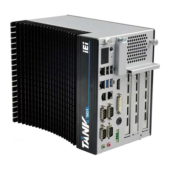
TANK-801 Em b e d de d S ys te m
MODEL:
TANK-801
Fa n le s s Em b e d d e d S ys te m with In te l® Ce le ro n ® J 1900 p ro c e s s o r,
DVI-I, Dis p la yP o rt, Two Gig a b it Eth e rn e t, RS -232/422/485,
Two US B 3.0, Two US B 2.0, Ro HS Co m p lia n t
Us e r Ma n u a l
P a g e i
Re v. 1.00 – 6 No ve m b e r, 2014
Advertisement
Table of Contents

Related Manuals for IEI Technology TANK-801


Summary of Contents for IEI Technology TANK-801
- Page 1 TANK-801 Em b e d de d S ys te m MODEL: TANK-801 Fa n le s s Em b e d d e d S ys te m with In te l® Ce le ro n ® J 1900 p ro c e s s o r, DVI-I, Dis p la yP o rt, Two Gig a b it Eth e rn e t, RS -232/422/485, Two US B 3.0, Two US B 2.0, Ro HS Co m p lia n t...
- Page 2 TANK-801 Em b e d d e d S ys te m Re vis io n Date Version Changes 6 November, 2014 1.00 Initial release P a g e ii...
- Page 3 TANK-801 Em b e d de d S ys te m Co p yrig h t COP YRIGHT NOTICE The information in this document is subject to change without prior notice in order to improve reliability, design and function and does not represent a commitment on the part of the manufacturer.
- Page 4 TANK-801 Em b e d d e d S ys te m WARNING This device complies with Part 15 of the FCC Rules. Operation is subject to the following two conditions: (1) this device may not cause harmful interference, and(2) this device must accept any interference received, including interference that may cause undesired operation.
-
Page 5: Table Of Contents
TANK-801 Em b e d de d S ys te m Ta b le o f Co n te n ts 1 INTRODUCTION ......................1 1.1 O ........................2 VERVIEW 1.2 M ....................3 ODEL ARIATIONS 1.3 F ........................3 EATURES 1.4 T... - Page 6 TANK-801 Em b e d d e d S ys te m 3.7.9 Power Input, 3-pin Terminal Block ..............30 3.7.10 Power Input, 4-pin DIN Connector ............... 30 3.7.11 RS-232/422/485 Serial Ports ................31 3.7.12 RS-232 Serial Port Connectors ..............33 3.7.13 USB Connectors .....................
- Page 7 TANK-801 Em b e d de d S ys te m 4.6 B ........................71 4.7 S & E ......................73 4.8 S ......................74 ERVER 4.8.1.1 System Event Log ..................75 4.8.1.2 BMC network configuration ..............76 A SAFETY PRECAUTIONS ..................77 A.1 S...
- Page 8 TANK-801 Em b e d d e d S ys te m Lis t o f Fig u re s Figure 1-1: TANK-801 ........................2 Figure 1-2: TANK-801 Peripheral Connectors ................6 Figure 1-3: TANK-801 LED Indicators ................... 7 Figure 1-4: 2P1E ..........................8 Figure 1-5: 1P2E ..........................
- Page 9 TANK-801 Em b e d de d S ys te m Figure 3-24: Serial Device Connector ..................34 Figure 3-25: Serial Port Pinout Location ..................34 Figure 3-26: USB Device Connection ..................36 Figure 3-27: Power Button ......................37 P a g e ix...
- Page 10 TANK-801 Em b e d d e d S ys te m Lis t o f Ta b le s Table 1-1: TANK-801 Model Variations ..................3 Table 1-2: Technical Specifications ....................5 Table 1-3: Supported Signals ......................9 Table 1-4: Rated Voltage and Current ..................9 Table 3-1: DIO Connector Pinouts ....................26...
-
Page 11: Introduction
TANK-801 Em b e d de d S ys te m Ch a p te r In tro d u c tio n P a g e 1... -
Page 12: Overview
It is powered by the Intel® Celeron® J1900 2.0GHz quad core processor and has 2.0 GB of DDR3L memory. The TANK-801 Series includes one DisplayPort, one DVI-I port, two PCIe GbE LAN, two USB 2.0 ports, two USB 3.0 ports and four COM ports. -
Page 13: Model Variations
TANK-801 Em b e d de d S ys te m 1.2 Mo d e l Va ria tio n s The model variations of the TANK-801 Series are listed below. Mo d e l No . CP U Exp a n s io n S lo ts Intel®... -
Page 14: Technical Specifications
TANK-801 Em b e d d e d S ys te m 1.4 Te c h n ic a l Sp e c ific a tio n s The TANK-801 technical specifications are listed in Table 1-2. S p e c ific a tio n s Fa n le s s Intel®... -
Page 15: Table 1-2: Technical Specifications
TANK-801 Em b e d de d S ys te m S p e c ific a tio n s Mini PCIe slot x 1 , In te rio r Exp e n s io n s SO-DIMM for IPMI... -
Page 16: Connector Panel
TANK-801 Em b e d d e d S ys te m 1.5 Co n n e c to r P a n e l All external peripheral interface connectors are located on the rear panel of the TANK-801. The peripheral interface connectors are shown in Figure 1-2. -
Page 17: Led Indicators
1 x ACC mode switch 1.6 LED In d ic a tors There are several indicators on the rear panel of the TANK-801 as shown in Figure 1-3. Figure 1-3: TANK-801 LED Indicators WARNING: The CPU Temperature Alert LED turns red when the CPU temperature is too high. -
Page 18: Backplane Options
TANK-801 Em b e d d e d S ys te m 1.7 Ba c kp la n e Op tio n s The backplane options of the TANK-801 are shown below. Figure 1-4: 2P1E Figure 1-5: 1P2E Figure 1-6: 3P0E... -
Page 19: Table 1-3: Supported Signals
TANK-801 Em b e d de d S ys te m The supported signals of the backplane slots are listed below. Ba c kp la n e S lo t S ig n a l 2P 1E PCIe x16 PCIe x1... -
Page 20: Dimensions
TANK-801 Em b e d d e d S ys te m NOTE: When using an expansion card with high power consumption, it is recommended to install an external power supply to the 12V power input connector on the backplane. -
Page 21: Unpacking
TANK-801 Em b e d de d S ys te m Ch a p te r Un p a c kin g P a g e 11... -
Page 22: Anti - Static Precautions
Follow the anti-static precautions outlined in Section 2.1. Make sure the packing box is facing upwards so the TANK-801 does not fall out of the box. Make sure all the components shown in Section 2.3 are present. -
Page 23: Unpacking Checklist
TANK-801 Em b e d de d S ys te m 2.3 Un pa c kin g Ch e c klis t NOTE: If some of the components listed in the checklist below are missing, please do not proceed with the installation. Contact the IEI reseller or vendor you purchased the TANK-801 from or contact an IEI sales representative directly. - Page 24 TANK-801 Em b e d d e d S ys te m Qu a n tity Ite m a n d P a rt Nu m b e r Im a g e S ta n d a rd HDD screw...
-
Page 25: Installation
TANK-801 Em b e d de d S ys te m Ch a p te r In s ta lla tio n P a g e 15... -
Page 26: Installation Precautions
Electric shock and personal injury might occur if the rear panel of the TANK-801 is opened while the power cord is still connected to an electrical outlet. -
Page 27: Figure 3-1: Cfast Socket
TANK-801 Em b e d de d S ys te m Figure 3-1: CFast Socket S te p 2: Open the CFast socket cover (Figure 3-2). Figure 3-2: CFast Socket Cover S te p 3: Correctly align the CFast card with the socket and insert the CFast card into the socket. -
Page 28: Hard Disk Drive (Hdd) Installation
TANK-801 Em b e d d e d S ys te m Figure 3-3: CF Card Installation S te p 4: Reinstall the cover. 3.3 Ha rd Dis k Drive (HDD) In s ta lla tio n To install the hard drive, please follow the steps below:... -
Page 29: Figure 3-5: Remove The Cover From Tank-801
TANK-801 Em b e d de d S ys te m S te p 2: Unplug the SATA signal and power cables connected to the TANK-801, and then put the cover on a flat surface (Figure 3-5). Figure 3-5: Remove the Cover from TANK-801... -
Page 30: System Fan Installation
Unplug the SATA signal and power cables connected to the TANK-801, and then S te p 2: place the cover on a flat surface (Figure 3-5). S te p 3: Attach the system fan to the TANK-801 and secure it by four retention screws (Figure 3-8). P a g e 20... -
Page 31: Pluggable Dc-I N Terminal Block Installation
TANK-801 Em b e d de d S ys te m Figure 3-8: System Fan Installation S te p 4: Connect the system fan cable to the CPU_FAN connector on the motherboard of TANK-801. Reconnect the SATA signal and power cables to the TANK-801. -
Page 32: Mounting The System With Mounting Brackets
TANK-801 Em b e d d e d S ys te m Figure 3-9: Pluggable DC-in Terminal Block Installation 3.6 Mo u n tin g th e S ys te m with Mo u n tin g Bra c ke ts To mount the embedded system onto a wall or some other surface using the two mounting brackets, please follow the steps below. -
Page 33: External Peripheral Interface Connectors
3.7 Exte rn a l P e rip h e ra l In te rfa c e Co n n e c to rs The TANK-801 has the following connectors. Detailed descriptions of the connectors can be found in the subsections below. -
Page 34: Acc Mode Selection
3.7.1 ACC Mo d e S e le c tio n The TANK-801 allows turning the ACC mode on or off. The setting can be made through the ACC mode switch on the external peripheral interface panel as shown below. -
Page 35: Audio Connector
Figure 3-13: Audio Connector 3.7.4 CFa s t S o c ke t The TANK-801 has one CFast socket. The location of the socket is shown in Figure 1-2. To install the CFast card, refer to Section 3.2. 3.7.5 Dig ita l In p u t/Ou tp u t Co n n e c to r... -
Page 36: Displayport Connector
TANK-801 Em b e d d e d S ys te m Figure 3-14: DIO Connector Pinout Location Figure 3-15: RJ-45 to DB-9 Cable (P/N: 32005-000200-200-RS) Description (RJ-45) Description (DB-9) DOUT3 DIN0 DOUT2 DIN2 DOUT1 DOUT0 DOUT0 DOUT2 DIN3 DIN2... -
Page 37: Dvi Connector
3.7.7 DVI Co n n e c to r The TANK-801 has one female DVI-I connector on the front panel. The DVI connectors are connected to digital display devices. To connect a digital display device to the TANK-801, please follow the instructions below. -
Page 38: Lan Connectors
TANK-801 Em b e d d e d S ys te m Figure 3-17: DVI Connector Secure the connector. Secure the DVI connector from the digital display device S te p 4: to the external interface by tightening the two retention screws on either side of the connector. -
Page 39: Figure 3-18: Lan Connection
TANK-801 Em b e d de d S ys te m Figure 3-18: LAN Connection Insert the LAN cable RJ-45 connector. Once aligned, gently insert the LAN S te p 3: cable RJ-45 connector into the on-board RJ-45 connector. Description... -
Page 40: Power Input, 3-Pin Terminal Block
TANK-801 Em b e d d e d S ys te m Activity/Link LED Speed LED DESCRIPTION STATUS DESCRIPTION STATUS No link 10 Mbps connection Yellow Linked Green 100 Mbps connection Blinking TX/RX activity Orange 1 Gbps connection Table 3-3: RJ-45 Ethernet Connector LEDs 3.7.9 P o we r In p u t, 3-p in Te rm in a l Blo c k... -
Page 41: Rs-232/422/485 Serial Ports
TANK-801 Em b e d de d S ys te m Figure 3-21: Power Input Connector Description Description +12V +12V Table 3-4: Power Input Pinouts 3.7.11 RS -232/422/485 S e ria l P o rts COM3, COM4 CN La b e l:... -
Page 42: Figure 3-22: Serial Device Connector
TANK-801 Em b e d d e d S ys te m Figure 3-22: Serial Device Connector Secure the connector. Secure the serial device connector to the external S te p 3: interface by tightening the two retention screws on either side of the connector. -
Page 43: Rs-232 Serial Port Connectors
TANK-801 Em b e d de d S ys te m Table 3-5: RS-232/422/485 Connector Pinouts 3.7.12 RS -232 S e ria l P o rt Co n n e c to rs COM1, COM2 CN La b e l:... -
Page 44: Figure 3-24: Serial Device Connector
TANK-801 Em b e d d e d S ys te m Figure 3-24: Serial Device Connector Secure the connector. Secure the serial device connector to the external S te p 3: interface by tightening the two retention screws on either side of the connector. -
Page 45: Usb Connectors
There are two USB 2.0 connectors and two USB 3.0 connectors on the TANK-801. To connect a USB device, please follow the instructions below. Locate the USB connectors. The locations of the USB connectors are shown S te p 1: in Figure 1-2. -
Page 46: Powering O N /Off The System
TANK-801 Em b e d d e d S ys te m Figure 3-26: USB Device Connection Insert the device connector. Once aligned, gently insert the USB device S te p 3: connector into the on-board connector. Description Description DATA-... -
Page 47: Figure 3-27: Power Button
TANK-801 Em b e d de d S ys te m the internal electronic components and may also cause injury to the user. Power on the system: press the power button for 2 seconds Power off the system: press the power button for 5 seconds... -
Page 48: Bios
TANK-801 Em b e d d e d S ys te m Ch a p te r BIOS P a g e 38... -
Page 49: Introduction
TANK-801 Em b e d de d S ys te m 4.1 In tro d u c tio n The BIOS is programmed onto the BIOS chip. The BIOS setup program allows changes to certain system settings. This chapter outlines the options that can be changed. -
Page 50: Getting Help
TANK-801 Em b e d d e d S ys te m Ke y Fu n c tio n Esc key Main Menu – Quit and not save changes into CMOS Status Page Setup Menu and Option Page Setup Menu --... -
Page 51: Main
TANK-801 Em b e d de d S ys te m The following sections completely describe the configuration options found in the menu items at the top of the BIOS screen and listed above. 4.2 Ma in The Main BIOS menu (BIOS Menu 1) appears when the BIOS Setup program is entered. -
Page 52: Advanced
TANK-801 Em b e d d e d S ys te m CPU Information Memory Information GDP Information TXE Information The Main menu has two user configurable fields: S ys te m Da te [xx/xx/xx] Use the System Date option to set the system date. -
Page 53: Acpi Settings
TANK-801 Em b e d de d S ys te m Aptio Setup Utility – Copyright (C) 2013 American Megatrends, Inc. Main Advanced Chipset Boot Security Save & Exit > ACPI Settings System ACPI Parameters > Super IO Configuration > Hardware Monitor >... -
Page 54: Super Io Configuration
TANK-801 Em b e d d e d S ys te m ACP I S le e p Sta te [S 3 (S u s p e n d to RAM)] Use the ACPI Sleep State option to specify the sleep state the system enters when it is not being used. -
Page 55: Serial Port N Configuration
TANK-801 Em b e d de d S ys te m 4.3.2.1 S e ria l P o rt n Co n fig u ra tio n Use the Serial Port n Configuration menu (BIOS Menu 5) to configure the serial port n. - Page 56 TANK-801 Em b e d d e d S ys te m Serial Port I/O port address is 3F8h and the IO=3F8h; IRQ=3, 4,5,6,7,9,10,11,12 interrupt address is IRQ3,4,5,6,7,9,10,11,12 IO=2F8h; IRQ=3, Serial Port I/O port address is 2F8h and the...
- Page 57 TANK-801 Em b e d de d S ys te m Serial Port I/O port address is 2E8h and the IO=2E8h; IRQ=3, 4,5,6,7,9,10,11,12 interrupt address is IRQ3,4,5,6,7,9,10,11,12 4.3.2.1.3 S e ria l P o rt 3 Co n fig u ra tio n ...
- Page 58 TANK-801 Em b e d d e d S ys te m De vic e Mo d e [RS 232] Use the Device Mode option to enable or disable the serial port. Enables serial port RS-232 support. RS232 EFAULT ...
-
Page 59: Hardware Monitor
TANK-801 Em b e d de d S ys te m Serial Port I/O port address is 2F0h and the IO=2F0h; IRQ=3, 4,5,6,7,9,10,11,12 interrupt address is IRQ3,4,5,6,7,9,10,11,12 IO=2E0h; IRQ=3, Serial Port I/O port address is 2E0h and the... -
Page 60: Smart Fan Mode Configuration
TANK-801 Em b e d d e d S ys te m P C He a lth Sta tu s The following system parameters and values are shown. The system parameters that are monitored are: System Temperatures: CPU Temperature System Temperature ... - Page 61 TANK-801 Em b e d de d S ys te m The fan adjusts its speed using these Auto PWM Mode settings: Temperature of Start Temperature of Off Start PWM Slope (Duty Cycle) Ma n u a l P WM S e ttin g Use the + or –...
- Page 62 TANK-801 Em b e d d e d S ys te m Setting this value too high may cause the fan to rotate at full speed only when the CPU is at a very high temperature and therefore cause the system to be damaged.
-
Page 63: Rtc Wake Settings
TANK-801 Em b e d de d S ys te m 4.3.4 RTC Wa ke S e ttin g s The RTC Wake Settings menu (BIOS Menu 8) configures RTC wake event. Aptio Setup Utility – Copyright (C) 2013 American Megatrends, Inc. -
Page 64: Serial Port Console Redirection
TANK-801 Em b e d d e d S ys te m If selected, the following appears with values that Enabled can be selected: *Wake up every day *Wake up date *Wake up hour *Wake up minute *Wake up second After setting the alarm, the computer turns itself on from a suspend state when the alarm goes off. - Page 65 TANK-801 Em b e d de d S ys te m Disabled the console redirection function Disabled EFAULT Enabled Enabled the console redirection function Te rm in a l Typ e [ANS I] Use the Terminal Type option to specify the remote terminal type..
- Page 66 TANK-801 Em b e d d e d S ys te m No parity bit is sent with the data bits. None EFAULT Even The parity bit is 0 if the number of ones in the data bits is even.
-
Page 67: Iei Feature
TANK-801 Em b e d de d S ys te m 4.3.6 iEi Fe a tu re Use the iEi Feature menu (BIOS Menu 10) to configure the iEi features. Aptio Setup Utility – Copyright (C) 2013 American Megatrends, Inc. -
Page 68: Socket 0 Cpu Information
TANK-801 Em b e d d e d S ys te m Aptio Setup Utility – Copyright (C) 2013 American Megatrends, Inc. Advanced CPU Configuration Socket specific CPU Information > Socket 0 CPU Information CPU Speed 2001 MHz ---------------------- 64-bit Supported : Select Screen... -
Page 69: Ide Configuration
TANK-801 Em b e d de d S ys te m Aptio Setup Utility – Copyright (C) 2013 American Megatrends, Inc. Advanced Socket 0 CPU Information Intel(R) Celeron(R) CPU J1900 @ 1.99GHz CPU Signature 30678 ---------------------- Microcode Patch Max CPU Speed 1990 MHz : Select Screen... - Page 70 TANK-801 Em b e d d e d S ys te m Aptio Setup Utility – Copyright (C) 2013 American Megatrends, Inc. Advanced IDE Configuration Select IDE / ACHI SATA Mode [AHCI Mode] Serial-ATA Controller 1 [Enabled] --------------------- SATA Port1 Hotplug [Disabled] : Select Screen...
-
Page 71: Trusted Computing
TANK-801 Em b e d de d S ys te m 4.3.9 Tru s te d Co m p u tin g Use the Trusted Computing menu (BIOS Menu 14) to configure settings related to the Trusted Computing Group (TCG) Trusted Platform Module (TPM). -
Page 72: Usb Configuration
TANK-801 Em b e d d e d S ys te m 4.3.10 US B Co n fig u ra tio n Use the USB Configuration menu (BIOS Menu 15) to read USB configuration information and configure the USB settings. -
Page 73: Chipset
TANK-801 Em b e d de d S ys te m Legacy USB support disabled Disabled Auto Legacy USB support disabled if no USB devices are connected 4.4 Ch ips e t Use the Chipset menu (BIOS Menu 16) to access the Northbridge and Southbridge configuration menus. -
Page 74: North Bridge Configuration
TANK-801 Em b e d d e d S ys te m 4.4.1 No rth Brid g e Co n fig u ra tio n Use the North Bridge menu (BIOS Menu 17) to configure the North Bridge chipset. Aptio Setup Utility – Copyright (C) 2013 American Megatrends, Inc. - Page 75 TANK-801 Em b e d de d S ys te m Auto Default DVMT P re -Allo c a te d [256M] Use the DVMT Pre-Allocated option to set the amount of system memory allocated to the integrated graphics processor when the system boots.
-
Page 76: South Bridge Configuration
TANK-801 Em b e d d e d S ys te m The spread spectrum mode is enabled Enabled 4.4.2 S o u th Brid g e Co n fig u ra tio n Use the South Bridge Configuration menu (BIOS Menu 18) to configure the Southbridge chipset. - Page 77 TANK-801 Em b e d de d S ys te m USB function support enabled Enabled EFAULT US B 2.0 (EHCI) S u p p o rt [En a b le d ] Use the USB 2.0 (EHCI) Support BIOS option to enable or disable USB 2.0 support.
-
Page 78: Azalia Hd Audio
TANK-801 Em b e d d e d S ys te m 4.4.2.1 Aza lia HD Au d io Use the Azalia HD Audio menu (BIOS Menu 19) to configure the Azalia HD audio settings. Aptio Setup Utility – Copyright (C) 2013 American Megatrends, Inc. -
Page 79: Pci Express Configuration
TANK-801 Em b e d de d S ys te m 4.4.2.2 P CI Exp re s s Co n fig u ra tio n Use the PCI Express Configuration menu (BIOS Menu 20) to select the support type of the PCIe Mini slot. -
Page 80: Security
TANK-801 Em b e d d e d S ys te m 4.5 S e c u rity Use the Security menu (BIOS Menu 21) to set system and user passwords. Aptio Setup Utility – Copyright (C) 2013 American Megatrends, Inc. -
Page 81: Boot
TANK-801 Em b e d de d S ys te m 4.6 Bo o t Use the Boot menu (BIOS Menu 22) to configure system boot options. Aptio Setup Utility – Copyright (C) 2013 American Megatrends, Inc. Boot Boot Configuration... - Page 82 TANK-801 Em b e d d e d S ys te m Qu ie t Bo o t [En a b le d ] Use the Quiet Boot BIOS option to select the screen display when the system boots.
-
Page 83: Save & Exit
TANK-801 Em b e d de d S ys te m 4.7 S a ve & Exit Use the Save & Exit menu (BIOS Menu 23) to load default BIOS values, optimal failsafe values and to save configuration changes. Aptio Setup Utility – Copyright (C) 2013 American Megatrends, Inc. -
Page 84: Server Mgmt
TANK-801 Em b e d d e d S ys te m S a ve a s Us e r De fa u lts Use the Save as User Defaults option to save the changes done so far as user defaults. -
Page 85: System Event Log
TANK-801 Em b e d de d S ys te m 4.8.1.1 S ys te m Eve n t Lo g Use the System Event Log menu (BIOS Menu 19) to configure the event log. Aptio Setup Utility – Copyright (C) 2013 American Megatrends, Inc. -
Page 86: Bmc Network Configuration
TANK-801 Em b e d d e d S ys te m Wh e n S EL is Fu ll [Do No th in g ] Use When SEL is FULL option to select options for reactions to a full SEL. The following options are available: ... -
Page 87: A Safety Precautions
TANK-801 Em b e d de d S ys te m Ap p e n d ix S a fe ty P re c a u tio n s P a g e 77... -
Page 88: Safety Precautions
TANK-801 Em b e d d e d S ys te m A.1 S a fe ty P re c a u tio n s WARNING: The precautions outlined in this appendix should be strictly followed. Failure to follow these precautions may result in permanent damage to the TANK-801. -
Page 89: Product Disposal
Electrostatic discharge (ESD) can cause serious damage to electronic components, including the TANK-801. Dry climates are especially susceptible to ESD. It is therefore critical that whenever the TANK-801 is opened and any of the electrical components are handled, the following anti-static precautions are strictly adhered to. -
Page 90: Maintenance And Cleaning Precautions
When maintaining or cleaning the TANK-801, please follow the guidelines below. A.2.1 Ma in te n a n c e a n d Cle a n in g Prior to cleaning any part or component of the TANK-801, please read the details below. ... - Page 91 TANK-801 Em b e d de d S ys te m Vacuum cleaner – Using a vacuum specifically designed for computers is one of the best methods of cleaning the TANK-801. Dust and dirt can restrict the airflow in the TANK-801 and cause its circuitry to corrode. ...
-
Page 92: B Digital I/O Interface
TANK-801 Em b e d d e d S ys te m Ap p e n d ix Dig ita l I/O In te rfa c e P a g e 82... -
Page 93: Introduction
B.1 In tro d u c tio n The DIO connector on the TANK-801 is interfaced to GPIO ports on the Super I/O chipset. The DIO has both 4-bit digital inputs and 4-bit digital outputs. The digital inputs and digital outputs are generally control signals that control the on/off circuit of external devices or TTL devices. -
Page 94: Assembly Language Sample 1
TANK-801 Em b e d d e d S ys te m B.2 As s e m b ly La n g u a g e S a m p le 1 AX, 6F08H ;setting the digital port as input AL low byte = value AH –... -
Page 95: C Hazardous Materials Disclosure
TANK-801 Em b e d de d S ys te m Ap p e n d ix Ha za rd o u s Ma te ria ls Dis c lo s u re P a g e 85... -
Page 96: Hazardous Materials Disclosure Table For Ipb Products Certified As R Ohs Compliant Under 2002/95/Ec Without Mercury
TANK-801 Em b e d d e d S ys te m C.1 Ha za rd o u s Ma te ria ls Dis c lo s u re Ta ble for IP B P ro d u c ts... - Page 97 TANK-801 Em b e d de d S ys te m P a rt Na m e To xic o r Ha za rd o u s S u b s ta n c e s a n d Ele m e n ts...
- Page 98 TANK-801 Em b e d d e d S ys te m 此附件旨在确保本产品符合中国 RoHS 标准。以下表格标示此产品中某有毒物质的含量符 合中国 RoHS 标准规定的限量要求。 本产品上会附有”环境友好使用期限”的标签,此期限是估算这些物质”不会有泄漏或突变”的 年限。本 产品可能包含有较短的环境友好使用期限的可替换元件,像是电池或灯管,这些元 件将会单独标示出来。 部件名称 有毒有害物质或元素 铅 汞 镉 六价铬 多溴联苯 多溴二苯 醚 (P b ) (Hg ) (Cd ) (CR(VI)) (P BB) (P BDE) 壳体...
Need help?
Do you have a question about the TANK-801 and is the answer not in the manual?
Questions and answers