
Related Manuals for AXIOMTEK MANO526


Summary of Contents for AXIOMTEK MANO526
- Page 1 MANO526 ® Intel Socket 1151 Core i7/ i5/ i3 Processors Mini ITX Motherboard User’s Manual...
- Page 2 Axiomtek does not make any commitment to update the information in this manual. Axiomtek reserves the right to change or revise this document and/or product at any time without notice. No part of this document may be reproduced, stored in a retrieval system, or transmitted, in any form or by any means, electronic, mechanical, photocopying, recording, or otherwise, without the prior written permission of Axiomtek Co., Ltd.
-
Page 3: Esd Precautions
It discharges static electricity from your body. ◼ Wear a wrist-grounding strap, available from most electronic component stores, when handling boards and components. Trademarks Acknowledgments Axiomtek is a trademark of Axiomtek Co., Ltd. ® ® Intel and Celeron are trademarks of Intel Corporation. -
Page 4: Table Of Contents
Table of Contents Disclaimers ...................... ii ESD Precautions ..................... iii Section 1 Introduction ..........1 Features ....................1 Specifications ..................2 Utilities Supported ................. 3 Block Diagram ..................4 Section 2 Board and Pin Assignments ....5 Board Layout ..................5 Rear I/O .................... - Page 5 Section 4 AMI BIOS Setup Utility ......25 Starting ....................25 Navigation Keys .................. 25 Main Menu ..................27 Advanced Menu .................. 28 Chipset Menu ..................41 Security Menu ..................46 Boot Menu ................... 47 Save & Exit Menu ................50 Appendix A Watchdog Timer ........
- Page 6 This page is intentionally left blank.
-
Page 7: Introduction
232/422/485, five RS-232) providing robust storage and I/O options. Users also can increase board functionality with PCI-Express x16 and M.2 slot. The high quality MANO526 allows two display interfaces via EDP, DisplayPort++ and HDMI in triplicate views, making it an ideal solution for gaming, workstation, digital signage, medical and other IoT&M2M applications. -
Page 8: Specifications
MANO526 Mini ITX Motherboard Specifications ⚫ Core™ i7/ i5/ i3 processors (up to ® ◼ LGA1151 Socket for 9 and 8 Generation Intel ® 65W CPU) and Pentium processor. ⚫ Chipset ® ◼ Intel Q370. ⚫ BIOS ◼ AMI BIOS via SPI interface. -
Page 9: Utilities Supported
MANO526 Mini ITX Motherboard ⚫ Power Input ◼ One ATX power input connector. ◼ One 12V ATX power input connector for CPU power. ⚫ Operating Temperature ◼ 0°C ~ 60°C. ⚫ Storage Temperature ◼ -10°C ~ 60°C. ⚫ Form Factor ◼... -
Page 10: Block Diagram
MANO526 Mini ITX Motherboard Block Diagram Introduction... -
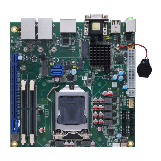
Page 11: Board And Pin Assignments
MANO526 Mini ITX Motherboard Section 2 Board and Pin Assignments Board Layout Top View Board and Pin Assignments... - Page 12 MANO526 Mini ITX Motherboard Bottom View Board and Pin Assignments...
-
Page 13: Rear I/O
MANO526 Mini ITX Motherboard Rear I/O Jumpers/Connectors 4-pin ATX Power Input Connector (CN22) Front Panel Connector (CN10) 24-pin ATX Power Input Connector (CN8) COM2 Data/Power Select Jumper (JP4) SATA 3.0 Connectors (CN25 ~ CN26) Digital I/O Connector (CN27) DDR4 SO-DIMM CHA~CHB Connectors USB 2.0 Wafer Connector (CN5) -
Page 14: Jumper And Switch Settings
2 jumper pins to close. And remove jumper clip from 2 jumper pins to open. The following illustration shows how to set up jumper. Before applying power to MANO526 Series, please make sure all of the jumper and switch are in factory default position. Below you can find a summary table of jumper, switch and onboard default settings. -
Page 15: Auto Power On (Jp1)
MANO526 Mini ITX Motherboard Jumper Description Setting Auto Power On 2-3 Close Default: Disable COM2 Pin 1: DCD# 3-5 Close COM2 Data/Power Select Default: RS-232 Data COM2 Pin 9: RI# 4-6 Close EDP VDD Select 1-2 Close Default: +3.3V Clear CMOS... -
Page 16: Clear Cmos (Sw1)
MANO526 Mini ITX Motherboard 2.3.4 Clear CMOS (SW1) This switch allows you to clear the Real Time Clock (RTC) RAM in CMOS. You can clear the CMOS memory of date, time, and system setup parameters by erasing the CMOS RTC RAM data. The onboard button cell battery powers the RAM data in CMOS, which includes system setup information such as system passwords. -
Page 17: Connectors
MANO526 Mini ITX Motherboard Connectors Signals go to other parts of the system through connectors. Loose or improper connection might cause problems, please make sure all connectors are properly and firmly connected. Here is a summary table showing connectors on the hardware. -
Page 18: Com Wafer Connectors (Cn1~Cn4)
MANO526 Mini ITX Motherboard 2.4.1 COM Wafer Connectors (CN1~CN4) The motherboard comes with four 2x5-pin (pitch=2.00mm) wafer connectors for COM3~COM6 serial port interfaces. Signal Signal DCD# 2.4.2 USB 2.0 Wafer Connector (CN5) These are 2x5-pin (pitch=2.00mm) connectors for USB 2.0 interfaces. -
Page 19: Atx Power Input Connectors (Cn8 And Cn22)
MANO526 Mini ITX Motherboard 2.4.3 ATX Power Input Connectors (CN8 and CN22) Steady and sufficient power can be supplied to all components on the board by connecting power connector. Please make sure all components and devices are properly installed before connecting the power connector. -
Page 20: Key E Connector (Cn9)
MANO526 Mini ITX Motherboard 2.4.4 M.2 Key E Connector (CN9) The motherboard comes with one M.2 Key E connector (Wi-Fi & Bluetooth). Pin Signal Pin Signal Pin Signal +3.3V PLTRST USB#9_D+ 28 CLKREQ +3.3V BT_DISABLE USB#9_D- WAKE WLAN_DISABLE SMBDAT PCIE11_TX_DP... -
Page 21: Front Panel Connector (Cn10)
MANO526 Mini ITX Motherboard 2.4.5 Front Panel Connector (CN10) The CN10 is a 2x7-pin (pitch=2.54mm) header for front panel interface. Signal Power LED+ SPK- BUZZER- Power LED- SPK+ PWR- PWR+ RESET- RESET+ HD LED- HD LED+ Power LED Pin 1 connects anode(+) of LED and pin 5 connects cathode(-) of LED. The power LED lights up when the system is powered on. -
Page 22: Key M Connector (Cn11)
MANO526 Mini ITX Motherboard 2.4.6 M.2 Key M Connector (CN11) The motherboard comes with one M.2 Key M connector suitable for mounting SATA/PCIE storage card. Pin Signal Pin Signal Pin Signal +3.3V CLKREQ CLKOUT_PCIE_N8 +3.3V PCIE#6_RXN PCIE#8_RXN CLKOUT_PCIE_P8 PCIE#6_RXP PCIE#8_RXP... -
Page 23: Lan And Usb 3.0 Ports (Cn13 And Cn14)
MANO526 Mini ITX Motherboard 2.4.7 LAN and USB 3.0 Ports (CN13 and CN14) The motherboard comes with two high performance plug and play Ethernet interfaces (RJ-45) which are fully compliant with the IEEE 802.3 standard. Connection can be established by plugging one end of the Ethernet cable into this RJ-45 connector and the other end to a 1000/100/10 Base-T hub. -
Page 24: Com Double-Deck D-Sub Connector (Cn16)
MANO526 Mini ITX Motherboard 2.4.8 COM Double-deck D-Sub Connector (CN16) The CN16 is a double-deck D-Sub connector for COM1 and COM2 serial port interfaces. Only COM2 is selectable for RS-232/422/485 mode by BIOS setting (see section 4.4). The pin assignments of RS-232/422/485 are listed in table below. -
Page 25: Fan Connectors (Cn23 And Cn24)
MANO526 Mini ITX Motherboard 2.4.10 Fan Connectors (CN23 and CN24) The motherboard has two fan connectors. You can find fan speed option within BIOS Setup Utility if fan is installed. For further information, see BIOS Setup Utility: Advanced\Hardware Monitor\PC Health Status in section 4.4. -
Page 26: Digital I/O Connector (Cn27)
MANO526 Mini ITX Motherboard 2.4.12 Digital I/O Connector (CN27) The motherboard comes with a 2x5-pin (pitch=2.00mm) header for 8-bit digital I/O interface. Signal Signal SIO_GPI70 (0xA06 Bit0, H) SIO_GPO77 SIO_GPI71 (0xA06 Bit5, H) (0xA06 Bit1, H) SIO_GPO76 SIO_GPI72 (0xA06 Bit6, H) -
Page 27: Displayport++ And Hdmi Connector (Cn30)
MANO526 Mini ITX Motherboard 2.4.14 DisplayPort++ and HDMI Connector (CN30) The motherboard comes with DisplayPort++ and HDMI interface on the rear I/O. DisplayPort++: USB Signal USB Signal DP_TX0_P DP_TX0_N DP_TX1_P DP_TX1_N DP_TX2_P DP_TX2_N DP_TX3_P DP_TX3_N DP_AUXP DP_AUXN DP_HPD +3.3V HDMI:... -
Page 28: Edp Connector (Scn1)
MANO526 Mini ITX Motherboard 2.4.15 eDP Connector (SCN1) The embedded DisplayPort (eDP) interface is available through 40-pin connector (SCN1), which is compliant with I-PEX-CABLINE II HT1 20143. Signal Signal EMB_HPD EDP_TXN3C EDP_TXP3_C EDP_TXN2_C EDP_TXP2_C EDP_TXN1_C EDP_TXP1_C EDP_TXN0_C EDP_TXP0_C EMB_AUXP EMB_AUXN... -
Page 29: Hardware Description
CPU from damages. BIOS The MANO526 Series uses AMI Plug and Play BIOS with a single SPI Flash. System Memory The MANO526 supports two 260-pin DDR4 SO-DIMM sockets for maximum memory capacity up to 32GB DDR4 SDRAMs. - Page 30 MANO526 Mini ITX Motherboard This page is intentionally left blank. Hardware Description...
-
Page 31: Ami Bios Setup Utility
MANO526 Mini ITX Motherboard Section 4 AMI BIOS Setup Utility The AMI UEFI BIOS provides users with a built-in setup program to modify basic system configuration. All configured parameters are stored in a flash chip to save the setup information whenever the power is turned off. - Page 32 MANO526 Mini ITX Motherboard Hot Keys Description → Left/Right The Left and Right <Arrow> keys allow you to select a setup screen. The Up and Down <Arrow> keys allow you to select a setup screen or sub Up/Down screen.
-
Page 33: Main Menu
MANO526 Mini ITX Motherboard Main Menu When you first enter the setup utility, you will enter the Main setup screen. You can always return to the Main setup screen by selecting the Main tab. System Time/Date can be set up as described below. -
Page 34: Advanced Menu
MANO526 Mini ITX Motherboard Advanced Menu The Advanced menu also allows users to set configuration of the CPU and other system devices. You can select any of the items in the left frame of the screen to go to the sub menus: ►... - Page 35 MANO526 Mini ITX Motherboard ⚫ IT8786 Super IO Configuration You can use this screen to select options for the Super IO Configuration, and change the value of the selected option. A description of the selected item appears on the right side of the screen.
- Page 36 MANO526 Mini ITX Motherboard ⚫ Serial Port 1 Configuration Serial Port Enable or disable serial port 1. The optimal setting for base I/O address is 3F8h and for interrupt request address is IRQ4. AMI BIOS Setup Utility...
- Page 37 MANO526 Mini ITX Motherboard ⚫ Serial Port 2 Configuration Serial Port Enable or disable serial port 2. The optimal setting for base I/O address is 2F8h and for interrupt request address is IRQ3. Serial Port 3~6 The optimal settings for base I/O address and interrupt request address are:...
- Page 38 MANO526 Mini ITX Motherboard ⚫ Hardware Monitor This screen monitors hardware health status. This screen displays the temperature of system and CPU, cooling fans speed in RPM and system voltages (VCORE, +12V, +5V, +3.3V and VBAT). AMI BIOS Setup Utility...
- Page 39 MANO526 Mini ITX Motherboard ⚫ Smart Fan Function This screen allows you to configure CPU fan and system fan mode. CPU FAN\System FAN This item allows you to select Smart Fan Mode: Full On: The fan always runs at full speed.
- Page 40 MANO526 Mini ITX Motherboard Automatic Mode: The following option selections appear only in Automatic Mode. Fan off temperature limit: The fan will off when temperature is lower than this limit. Fan start temperature limit: The fan will work when temperature is higher than this limit.
- Page 41 MANO526 Mini ITX Motherboard ⚫ NVMe Configuration This screen displays NVMe (Non-Volatile Memory Express) controller and drive information. ⚫ ACPI Settings ACPI Sleep State When the suspend button is pressed, the ACPI (Advanced Configuration and Power Interface) sleep state is S3 (Suspend to RAM).
- Page 42 MANO526 Mini ITX Motherboard ⚫ Trusted Computing This screen provides function for specifying the TPM settings. Security Device Support Enable or disable BIOS support for security device. Pending operation Schedule an operation for the security device, see image below. None TPM Clear: Clear all data secured by TPM.
- Page 43 MANO526 Mini ITX Motherboard ⚫ CPU Configuration This screen shows CPU information, and you can change the value of the selected option. Intel (VMX) Virtualization Technology Enable or disable Intel Virtualization Technology. When enabled, a VMM (Virtual Machine Mode) can utilize the additional hardware capabilities. It allows a platform to run multiple operating systems and applications independently, hence enabling a single computer system to work as several virtual systems.
- Page 44 MANO526 Mini ITX Motherboard Turbo Mode Enable or disable Intel ® turbo boost mode allowing processor cores to run faster but not exceed CPU defined frequency limits. AMI BIOS Setup Utility...
- Page 45 MANO526 Mini ITX Motherboard ⚫ SATA and RST Configuration During system boot up, BIOS automatically detects the presence of SATA devices. In the SATA Configuration menu, you can see the currently installed hardware in the SATA ports. SATA Controller(s) Enable or disable the SATA Controller feature. The default is Enabled.
- Page 46 MANO526 Mini ITX Motherboard ⚫ PCH-FW Configuration This screen displays ME Firmware information. ⚫ USB Configuration USB Devices Display all detected USB devices. AMI BIOS Setup Utility...
-
Page 47: Chipset Menu
MANO526 Mini ITX Motherboard Chipset Menu The Chipset menu allows users to change the advanced chipset settings. You can select any of the items in the left frame of the screen to go to the sub menus: ► System Agent (SA) Configuration ►... - Page 48 MANO526 Mini ITX Motherboard System Agent (SA) Configuration ⚫ This screen allows users to configure System Agent (SA) parameters. For items marked with “”, please press <Enter> for more options. Graphics Configuration Open sub menu for parameters related to graphics configuration.
- Page 49 MANO526 Mini ITX Motherboard ⚫ Graphics Configuration Primary IGFX Boot Display Select the video device which will be activated during POST (Power-On Self Test). The secondary boot display selection will appear based on your selection. AMI BIOS Setup Utility...
- Page 50 MANO526 Mini ITX Motherboard ⚫ Memory Configuration This screen shows the system memory information. AMI BIOS Setup Utility...
- Page 51 MANO526 Mini ITX Motherboard ⚫ PCH-IO Configuration This screen allows you to set PCH parameters. PCH LAN Controller Enable or disable onboard PCH LAN controller. Wake on LAN Enable After enabling PCH LAN Controller, you can enable or disable integrated LAN to wake the system.
-
Page 52: Security Menu
MANO526 Mini ITX Motherboard Security Menu The Security menu allows users to change the security settings for the system. ⚫ Setup Administrator Password Set setup administrator password. ⚫ User Password Set user password. AMI BIOS Setup Utility... -
Page 53: Boot Menu
MANO526 Mini ITX Motherboard Boot Menu The Boot menu allows users to change boot options of the system. ⚫ Setup Prompt Timeout Number of seconds to wait for setup activation key. 65535(0xFFFF) means indefinite waiting. ⚫ Bootup NumLock State Use this item to select the power-on state for the keyboard NumLock. - Page 54 MANO526 Mini ITX Motherboard ⚫ Launch UEFI PXE OpROM policy Control the execution of UEFI PXE OpROM. When enabled, you may select LAN1 or LAN2 as PXE LAN port. ⚫ Boot Option Priorities These are settings for boot priority. Specify the boot device priority sequence from the available devices.
- Page 55 MANO526 Mini ITX Motherboard ⚫ Boot Mode Use this option for boot mode settings. UEFI Boot: Select support to boot any UEFI-capable OS. Legacy Boot: Select support to boot non UEFI-capable OS that expects a legacy BIOS interface. AMI BIOS Setup Utility...
-
Page 56: Save & Exit Menu
MANO526 Mini ITX Motherboard Save & Exit Menu The Save & Exit menu allows users to load your system configuration with optimal or fail-safe default values. ⚫ Save Changes and Exit When you have completed the system configuration changes, select this option to leave Setup and return to Main Menu. - Page 57 MANO526 Mini ITX Motherboard ⚫ Discard Changes Select this option to quit Setup without making any permanent changes to the system configuration. Select Discard Changes from the Save & Exit menu and press <Enter>. Select Yes to discard changes. ⚫...
- Page 58 MANO526 Mini ITX Motherboard This page is intentionally left blank. AMI BIOS Setup Utility...
-
Page 59: Appendix A Watchdog Timer
MANO526 Mini ITX Motherboard Appendix A Watchdog Timer About Watchdog Timer Software stability is major issue in most application. Some embedded systems are not watched by human for 24 hours. It is usually too slow to wait for someone to reboot when computer hangs. - Page 60 MANO526 Mini ITX Motherboard This page is intentionally left blank. Watchdog Timer...
-
Page 61: Appendix B Digital I/O
MANO526 Mini ITX Motherboard Appendix B Digital I/O B.1 Digital I/O Program SOP Enter ADU, and press <F4> to select the superior ITE. PORT setting 2Eh, 2Fh. Address 07h setting 07 GPIO. Address CEh to set the input/output (1:OUT 0:IN), for example address CEh is 0Fh ->... - Page 62 MANO526 Mini ITX Motherboard This page is intentionally left blank. Digital I/O...
-
Page 63: Appendix C Configuring Sata For Raid
MANO526 Mini ITX Motherboard Appendix C Configuring SATA for RAID Configuring SATA Hard Drive(s) for RAID Function Before you begin the SATA configuration, please prepare: Two SATA hard drives (to ensure optimal performance, it is recommended that you use two ⚫... - Page 64 MANO526 Mini ITX Motherboard Turn on your system, and then press the <Del> button to enter BIOS Setup during running 2.1. POST (Power-On Self Test). If you want to create RAID, just go to the Advanced Settings menu/SATA and RST Configuration, select the “SATA Mode Selection”, and press <Enter>...
- Page 65 MANO526 Mini ITX Motherboard 3. Configuring RAID. Configure a RAID array. If you want to create a RAID array, select the Intel(R) Rapid 3.1. Storage Technology option and press <Enter>. Configuring SATA for RAID...
- Page 66 MANO526 Mini ITX Motherboard After entering the Create RAID Volume screen, you can type the disk array name with 1~16 3.2. letters or less (letters cannot be special characters) in the item “Name”. Then select a RAID level. There are three RAID levels: RAID0 (Stripe), RAID1 (Mirror) and 3.3.
- Page 67 MANO526 Mini ITX Motherboard Don’t forget to Select Disks by typing “X” as indicated in image below. Set the stripe block size. The KB is the standard unit of stripe block size. The stripe block 3.4. size can be 4KB to 128KB.
- Page 68 MANO526 Mini ITX Motherboard After the setting, proceed to next step for the array capacity setting. 3.5. After setting all the items on the screen, select Create Volume to start creating the RAID 3.6. array. Configuring SATA for RAID...
- Page 69 MANO526 Mini ITX Motherboard After the creation is completed, you can see detailed information about the RAID Array in the following screen, including disk name, RAID level, disk block size and disk capacity, etc. Delete RAID volume If you want to delete a RAID volume, select the Delete option and follow on-screen instructions.
- Page 70 MANO526 Mini ITX Motherboard This page is intentionally left blank. Configuring SATA for RAID...
-
Page 71: Appendix D Iamt Settings
MANO526 Mini ITX Motherboard Appendix D iAMT Settings Utilizing built-in platform capabilities and popular third-party management and security applications, the Intel ® Active Management Technology (Intel ® iAMT) has significantly lowered a major barrier to IT management efficiency, helping IT professionals discover, repair and better protect their networked computing assets. - Page 72 MANO526 Mini ITX Motherboard You will be asked to change the password before setting ME. You must confirm your new password while revising. The new password must consist of eight characters, including at least: ⚫ One upper case ⚫ One lower case ⚫...
-
Page 73: Iamt Settings
MANO526 Mini ITX Motherboard iAMT Settings ® Select Intel iAMT configuration and press <Enter>. Select Network Setup to configure iAMT. iAMT Settings... - Page 74 MANO526 Mini ITX Motherboard Select TCP/IP to get into Network interface and set it to Enabled. Get into DHCP Mode and set it to Disabled. iAMT Settings...
- Page 75 MANO526 Mini ITX Motherboard If DHCP Mode is disabled, set the following settings: ⚫ IP address ⚫ Subnet mask Go back to Intel ® iAMT Configuration, then select Activate Network Access and press <Enter>. Exit from MEBx after completing the iAMT settings.
-
Page 76: Iamt Web Console
MANO526 Mini ITX Motherboard iAMT Web Console On a web browser, type http://(IP ADDRESS):16992, which connects to iAMT Web. Example: http://10.1.40.214:16992 To log on, you will be required to type in username and password for access to the Web. USER: admin (default value) - Page 77 MANO526 Mini ITX Motherboard Enter the iAMT Web. Click Remote Control, and select commands on the right side. When you have finished using the iAMT Web console, close the Web browser. iAMT Settings...
- Page 78 MANO526 Mini ITX Motherboard This page is intentionally left blank. iAMT Settings...
-
Page 79: Appendix Etpm Settings
MANO526 Mini ITX Motherboard Appendix E TPM Settings 1. Setup BitLocker Drive Encryption main storage. Press <Win + R> and type “Control Panel”, then select BitLocker Drive Encryption. TPM Settings... - Page 80 MANO526 Mini ITX Motherboard 2. Insert an external storage device, for example USB Storage. Back up BitLocker recovery key in a new file and save it to the USB Storage. TPM Settings...
- Page 81 MANO526 Mini ITX Motherboard 3. Please follow the steps below to encrypt your storage device: TPM Settings...
- Page 82 MANO526 Mini ITX Motherboard Now, the system prompts that the operating system drive encryption is in progress, and the encryption progress is checked. TPM Settings...
- Page 83 MANO526 Mini ITX Motherboard Select and click the icon in the lower right corner to complete the encryption. TPM Settings...
- Page 84 MANO526 Mini ITX Motherboard 4. Confirm the completion of encryption. TPM Settings...
- Page 85 MANO526 Mini ITX Motherboard 5. Disable TPM function in BIOS Setup Utility. 6. When the system is powered on and you see the following screen, it means the TPM module function is working fine. Note that BitLocker cannot be executed if your system does not have TPM function.
- Page 86 MANO526 Mini ITX Motherboard System with no TPM function support is as below: TPM information is not found in Device Manager. Note When trying to turn on Bitlocker, the following error message shows up. TPM Settings...
- Page 87 MANO526 Mini ITX Motherboard TPM Settings...
Need help?
Do you have a question about the MANO526 and is the answer not in the manual?
Questions and answers