
Subscribe to Our Youtube Channel
Related Manuals for AXIOMTEK MANO566


Summary of Contents for AXIOMTEK MANO566
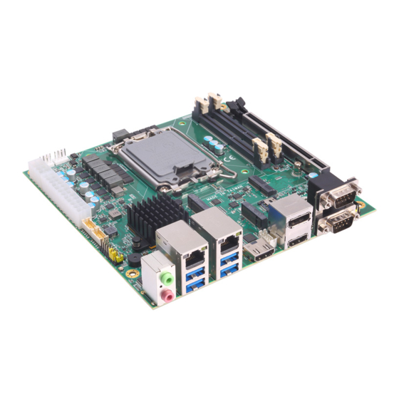
- Page 1 MANO566 ® Intel Socket 1700 Core i7/ i5/ i3 Series Processors Mini ITX Motherboard User’s Manual...
- Page 2 Axiomtek does not make any commitment to update the information in this manual. Axiomtek reserves the right to change or revise this document and/or product at any time without notice. No part of this document may be reproduced, stored in a retrieval system, or transmitted, in any form or by any means, electronic, mechanical, photocopying, recording, or otherwise, without the prior written permission of Axiomtek Co., Ltd.
-
Page 3: Esd Precautions
It discharges static electricity from your body. ◼ Wear a wrist-grounding strap, available from most electronic component stores, when handling boards and components. Trademarks Acknowledgments Axiomtek is a trademark of Axiomtek Co., Ltd. ® ® Intel and Celeron are trademarks of Intel Corporation. -
Page 4: Table Of Contents
Table of Contents Disclaimers ...................... ii ESD Precautions ..................... iii Section 1 Introduction ..........1 Features ....................1 Specifications ..................3 Utilities Supported ................. 4 Block Diagram ..................5 Section 2 Board and Pin Assignments ....6 Board Layout ..................6 Jumper and Switch Settings .............. - Page 5 Section 4 AMI BIOS Setup Utility ......26 Starting ....................26 Navigation Keys .................. 26 Main Menu ..................28 Advanced Menu .................. 29 Chipset Menu ..................44 Security Menu ..................51 Boot Menu ................... 53 Save & Exit Menu ................54 Appendix A Watchdog Timer ........
- Page 6 This page is intentionally left blank.
-
Page 7: Introduction
232/422/485, five RS-232) providing robust storage and I/O options. Users also can increase board functionality with PCI-Express x16 and M.2 slot. The high quality MANO566 allows two display interfaces via EDP, DisplayPort++ and HDMI in triplicate views, making it an ideal solution for gaming, workstation, digital signage, medical and other IoT&M2M applications. - Page 8 MANO566 Mini ITX Motherboard Introduction...
-
Page 9: Specifications
MANO566 Mini ITX Motherboard Specifications ⚫ ® ◼ LGA1700Socket for 12 Generation Intel Core™ i7/ i5/ i3 processors (up to 65W ® CPU) and Pentium processor. ⚫ Chipset ® ◼ Intel Q670E ® ◼ Intel R680E (Option) ® ◼ Intel H610E (Option) ⚫... -
Page 10: Utilities Supported
MANO566 Mini ITX Motherboard ⚫ Power Input ◼ One ATX power input connector. ◼ One 12V ATX power input connector for CPU power. ⚫ Operating Temperature ◼ 0°C ~ 60°C. ⚫ Storage Temperature ◼ -10°C ~ 60°C. ⚫ Form Factor ◼... -
Page 11: Block Diagram
MANO566 Mini ITX Motherboard Block Diagram Introduction... -
Page 12: Board And Pin Assignments
MANO566 Mini ITX Motherboard Section 2 Board and Pin Assignments Board Layout Top View Rear I/O Board and Pin Assignments... - Page 13 MANO566 Mini ITX Motherboard Bottom View Board and Pin Assignments...
-
Page 14: Jumper And Switch Settings
2 jumper pins to close. And remove jumper clip from 2 jumper pins to open. The following illustration shows how to set up jumper. Before applying power to MANO566 Series, please make sure all of the jumper and switch are in factory default position. Below you can find a summary table of jumper, switch and onboard default settings. -
Page 15: Auto Power On (Jp1)
MANO566 Mini ITX Motherboard 2.3.1 Auto Power On (JP1) If JP1 is enabled for power input, the system will be automatically power on without pressing soft power button. If JP1 is disabled for power input, it is necessary to manually press soft power button to power on the system. -
Page 16: Connectors
MANO566 Mini ITX Motherboard Connectors Signals go to other parts of the system through connectors. Loose or improper connection might cause problems, please make sure all connectors are properly and firmly connected. Here is a summary table showing connectors on the hardware. -
Page 17: Fan Connectors (Cn1 And Cn2)
MANO566 Mini ITX Motherboard 2.4.1 Fan Connectors (CN1 CPU Fan and CN2 SYS Fan) The motherboard has two 4-pin (pitch=2.54mm) fan connectors. You can find fan speed option within BIOS Setup Utility if fan is installed. For further information, see BIOS Setup Utility: Advanced\Hardware Monitor\PC Health Status in section 4.4. -
Page 18: Usb 2.0 Wafer Connector (Cn5 And Cn6)
MANO566 Mini ITX Motherboard 2.4.3 USB 2.0 Wafer Connector (CN5 and CN6) These are 2x5-pin (Pitch=2.00mm/Model:CSI-2211-101R) connectors for USB 2.0 interfaces. CN5/CN6: Signal Signal USB VCC USB VCC (+5V_SBY) (+5V_SBY) USB_D5_N USB_D6_N USB_D5_P USB_D6_P Board and Pin Assignments... -
Page 19: Key M Connector (Cn7)
MANO566 Mini ITX Motherboard 2.4.4 M.2 Key M Connector (CN7) The motherboard comes with one M.2 Key M connector suitable for mounting SATA/PCIE storage card. Signal Signal +3.3V +3.3V PCIE_RX3_N PCIE_RX3_P PCIE_TX3_N +3.3V PCIE_TX3_P +3.3V +3.3V PCIE_RX2_N +3.3V PCIE_RX2_P PCIE_TX2_N... -
Page 20: Key E Connector (Cn8)
MANO566 Mini ITX Motherboard 2.4.5 M.2 Key E Connector (CN8) The motherboard comes with one M.2 Key E connector. Signal Pin Signal +3.3V USB_D+ +3.3V USB_D- KEY E KEY E PCIE_TX_P PCIE_TX_N PCIE_RX_P PCIE_RX_N REF_CLK_P REF_CLK_N SUSCLK PERST# CLKREQ# W_DISABLE2#... -
Page 21: Front Panel Connector (Cn9)
MANO566 Mini ITX Motherboard 2.4.6 Front Panel Connector (CN9) The CN9 is a 2x7-pin (pitch=2.54mm) header for front panel interface. Signal Power LED+ SPK- BUZZER- Power LED- SPK+ PWRSW- PWRSW+ HWRST- HWRST+ HDDLED- HDDLED+ Power LED Pin 1 connects LED+ and pin 5 connects LED-. The power LED lights up when the system is powered on. -
Page 22: Nano Sim Socket (Cn10)
MANO566 Mini ITX Motherboard 2.4.7 Nano SIM Socket (CN10) The motherboard is equipped with CN10 socket for inserting SIM Card. Signal SIM VCC SIM Reset SIM CLK SIM VPP SIM Data 2.4.8 SATA Connectors (CN11 and CN12) This Serial Advanced Technology Attachment (Serial ATA or SATA) connector is for SATA 3.0 interface allowing up to 6.0Gb/s data transfer rate. -
Page 23: Key B Connector (Cn13)
MANO566 Mini ITX Motherboard 2.4.9 M.2 Key B Connector (CN13) The motherboard comes with one M.2 Key B connector suitable for mounting SATA/PCIE storage card, USB 3.0 and USB 2.0 application card. Signal Signal CONFIG_3 +3.3V_SBY +3.3V_SBY Full Card PWR OFF_SBY (+1.8V) USB_DP W_DISABLE1#_SBY (+3.3V) -
Page 24: Com Wafer Connectors (Cn14 And Cn16)
MANO566 Mini ITX Motherboard 2.4.10 COM Wafer Connectors (CN14 and CN16) The motherboard comes with two 2x5-pin (Pitch=2.00mm/Model: 520-90-10GB00) wafer connectors for COM3 and COM4 serial port interfaces. Both COM3 and COM4 are selectable for RS-232/422/485 mode by BIOS setting (see section 4.4). The pin assignments of RS-232/422/485 are listed in table below. -
Page 25: Lan And Usb 3.2 Ports (Cn17 And Cn18)
MANO566 Mini ITX Motherboard 2.4.12 LAN and USB 3.2 Ports (CN17 and CN18) The motherboard comes with two high performance plug and play Ethernet interfaces (RJ-45) which are fully compliant with the IEEE 802.3 standard. Connection can be established by plugging one end of the Ethernet cable into this RJ-45 connector and the other end to a 2500/1000/100/10 Base-T hub. -
Page 26: Displayport++ And Hdmi Connector (Cn19)
MANO566 Mini ITX Motherboard 2.4.13 DisplayPort++ and HDMI Connector (CN19) The motherboard comes with DisplayPort++ and HDMI interface on the rear I/O. Signal Signal LANE 0 DATA2 LANE 0# DATA2# LANE 1 DATA1 LANE 1# DATA1# LANE 2 DATA0 LANE 2#... -
Page 27: Com Double-Deck D-Sub Connector (Cn21)
MANO566 Mini ITX Motherboard 2.4.15 COM Double-deck D-Sub Connector (CN21) The CN21 is a double-deck D-Sub connector for COM1 and COM2 serial port interfaces. Both COM1 and COM2 are selectable for RS-232/422/485 mode by BIOS setting (see section 4.4). The pin assignments of RS-232/422/485 are listed in table below. (Maximum... -
Page 28: Edp Connector (Scn2)
MANO566 Mini ITX Motherboard 2.4.17 eDP Connector (SCN2) The embedded DisplayPort (eDP) interface is available through 40-pin connector (SCN2), which is compliant with I-PEX-CABLINE II HT1 20143. Signal Signal +DVCCM eDP_TXN0 +DVCCM eDP_TXP0 +DVCCM +DVCCM eDP_AUX_DP eDP_AUX_DN eDP_HPD# eDP_TXN3 eDP_BLT_CTRL... - Page 29 MANO566 Mini ITX Motherboard This page is intentionally left blank. Board and Pin Assignments...
-
Page 30: Hardware Description
CPU from damages. BIOS The MANO566 Series uses AMI Plug and Play BIOS with a single SPI Flash. System Memory The MANO566 supports two 260-pin DDR4 SO-DIMM sockets for maximum memory capacity up to 32GB DDR4 SDRAMs. - Page 31 MANO566 Mini ITX Motherboard This page is intentionally left blank. Hardware Description...
-
Page 32: Ami Bios Setup Utility
MANO566 Mini ITX Motherboard Section 4 AMI BIOS Setup Utility The AMI UEFI BIOS provides users with a built-in setup program to modify basic system configuration. All configured parameters are stored in a flash chip to save the setup information whenever the power is turned off. - Page 33 MANO566 Mini ITX Motherboard Hot Keys Description → Left/Right The Left and Right <Arrow> keys allow you to select a setup screen. The Up and Down <Arrow> keys allow you to select a setup screen or sub Up/Down screen.
-
Page 34: Main Menu
MANO566 Mini ITX Motherboard Main Menu When you first enter the setup utility, you will enter the Main setup screen. You can always return to the Main setup screen by selecting the Main tab. System Time/Date can be set up as described below. -
Page 35: Advanced Menu
MANO566 Mini ITX Motherboard Advanced Menu The Advanced menu also allows users to set configuration of the CPU and other system devices. You can select any of the items in the left frame of the screen to go to the sub menus: ►... - Page 36 MANO566 Mini ITX Motherboard ⚫ Device Configuration A description of the selected item appears on the right side of the screen. For items marked with “”, please press <Enter> for more options. Onboard Device Configuration Use this option to configure onboard device (e.g., Digital I/O setting).
- Page 37 MANO566 Mini ITX Motherboard ⚫ Onboard Configuration You can use this screen to select options for Digital I/O Configuration. DIO Modification Enable or disable digital I/O modification. The default is Disabled. DIO port 1-8 Select this option to open DIO status sub-screen.
- Page 38 MANO566 Mini ITX Motherboard ⚫ Configuration This screen shows CPU information, and you can change the value of the selected option. Hyper-Threading Enable or disable Hyper-Threading Technology. When enabled, it allows a single physical processor to multitask as multiple logical processors. When disabled, only one thread per enabled core is enabled.
- Page 39 MANO566 Mini ITX Motherboard ⚫ Trusted Computing This screen provides function for specifying the TPM (Trusted Platform Module) settings. Security Device Support Enable or disable BIOS support for security device. AMI BIOS Setup Utility...
- Page 40 MANO566 Mini ITX Motherboard ⚫ ACPI Settings You can use this screen to select options for the ACPI configuration, and change the value of the selected option. A description of the selected item appears on the right side of the screen.
- Page 41 MANO566 Mini ITX Motherboard ⚫ Storage Configuration You can use this screen to select options for storage configuration, and change the value of the selected option. A description of the selected item appears on the right side of the screen. For items marked with “”, please press <Enter> for more options.
- Page 42 MANO566 Mini ITX Motherboard SATA Controller(s) Enable or disable the SATA Controller feature. Intel *VMD setup menu Allows user to configure the VMD controllers. Enable VMD controller Enable or disable to VMD controller. *Intel Volume Management Device AMI BIOS Setup Utility...
- Page 43 MANO566 Mini ITX Motherboard ⚫ NVMe Configuration This screen displays NVMe (Non-Volatile Memory Express) controller and drive information. AMI BIOS Setup Utility...
- Page 44 MANO566 Mini ITX Motherboard ⚫ F81966 Super Configuration You can use this screen to select options for the Super IO Configuration, and change the value of the selected option. A description of the selected item appears on the right side of the screen.
- Page 45 MANO566 Mini ITX Motherboard ⚫ Serial Port 1 Configuration Serial Port Enable or disable serial port 1. The optimal setting for base I/O address is 3F8h and for interrupt request address is IRQ4. Serial Port 2~4 The optimal settings for base I/O address and interrupt request address are:...
- Page 46 MANO566 Mini ITX Motherboard ⚫ Hardware Monitor Monitors hardware health status. This screen displays the temperature of system, cooling fans speed in RPM and system voltages (+5VDUAL, VCC_RTC, +5V, VSB3V and VSB5V). AMI BIOS Setup Utility...
- Page 47 MANO566 Mini ITX Motherboard Smart Configuration Allows user to configure CPU fan and system fan mode. Smart Fan Function Enable or disable Smart Fan: Enable: Fan speed would change according to temperature. Disable: The fan always runs at full speed.
- Page 48 MANO566 Mini ITX Motherboard ⚫ Configuration USB Devices Display all detected USB devices. AMI BIOS Setup Utility...
- Page 49 MANO566 Mini ITX Motherboard ⚫ Configuration Use this screen to configure AMT parameters. AMT BIOS Features Enable or disable Active Management Technology BIOS features. AMI BIOS Setup Utility...
-
Page 50: Chipset Menu
MANO566 Mini ITX Motherboard Chipset Menu The Chipset menu allows users to change the advanced chipset settings. You can select any of the items in the left frame of the screen to go to the sub menus: ► System Agent (SA) Configuration ►... - Page 51 MANO566 Mini ITX Motherboard System Agent (SA) Configuration ⚫ This screen allows users to configure System Agent (SA) parameters. For items marked with “”, please press <Enter> for more options. Graphics Configuration Open sub menu for parameters related to graphics configuration.
- Page 52 MANO566 Mini ITX Motherboard ⚫ Graphics Configuration Internal Graphics Use this item to set parameters related to internal graphics controller. AMI BIOS Setup Utility...
- Page 53 MANO566 Mini ITX Motherboard ⚫ Memory Configuration This screen displays the system memory information. AMI BIOS Setup Utility...
- Page 54 MANO566 Mini ITX Motherboard ⚫ PCH-IO Configuration This screen allows you to set PCH parameters. PCI Express Configuration PCI-Express Configuration settings. PCI Express Root Port 4(M.2 E Key) Control the PCI-Express root port(M.2 E Key). AMI BIOS Setup Utility...
- Page 55 MANO566 Mini ITX Motherboard PCIe Speed Allow user to configure PCI-Express speed. ASPM Sets the ASPM (Active State Power Management Settings) level: Force L0: Force all links to LO state. Auto: BIOS auto configures. Disabled: Disables ASPM. Hot Plug Enable or disable PCI-Express Hot Plug.
- Page 56 MANO566 Mini ITX Motherboard HD Audio Configuration HD Audio subsystem configuration settings. HD Audio Control detection of the HD Audio device. Disabled: HDA will be unconditionally disabled. Enabled: HDA will be unconditionally enabled. AMI BIOS Setup Utility...
-
Page 57: Security Menu
MANO566 Mini ITX Motherboard Security Menu The Security menu allows users to change the security settings for the system. ⚫ Administrator Password Set administrator password. ⚫ User Password Set password. AMI BIOS Setup Utility... - Page 58 MANO566 Mini ITX Motherboard ⚫ Secure Boot Secure Boot Secure Boot feature is Active if Secure Boot is Enabled, Platform Key (PK) is enrolled and the System is in User mode. The mode change requires platform reset. Secure Boot ensures that the system only boots from trusted software, preventing malicious software from loading and compromising the device.
-
Page 59: Boot Menu
MANO566 Mini ITX Motherboard Boot Menu The Boot menu allows users to change boot options of the system. ⚫ Setup Prompt Timeout Number of seconds to wait for setup activation key. 65535(0xFFFF) means indefinite waiting. ⚫ Bootup NumLock State Use this item to select the power-on state for the keyboard NumLock. -
Page 60: Save & Exit Menu
MANO566 Mini ITX Motherboard Save & Exit Menu The Save & Exit menu allows users to load your system configuration with optimal or fail-safe default values. ⚫ Save Changes Exit When you have completed the system configuration changes, select this option to leave Setup and return to Main Menu. - Page 61 MANO566 Mini ITX Motherboard ⚫ Discard Changes Select this option to quit Setup without making any permanent changes to the system configuration. Select Discard Changes from the Save & Exit menu and press <Enter>. Select Yes to discard changes. ⚫...
-
Page 62: Appendix A Watchdog Timer
MANO566 Mini ITX Motherboard Appendix A Watchdog Timer About Watchdog Timer Software stability is major issue in most application. Some embedded systems are not watched by human for 24 hours. It is usually too slow to wait for someone to reboot when computer hangs. - Page 63 MANO566 Mini ITX Motherboard This page is intentionally left blank. Watchdog Timer...
-
Page 64: Appendix B Digital I/O
MANO566 Mini ITX Motherboard Appendix B Digital I/O B.1 Digital I/O Programming IOBASE: 0xEFA0 Registers: Command byte The command byte is the first byte to follow the address byte during a write transmission. It is used as a pointer to determine which of the following registers will be written or read. -
Page 65: B.2 Sample Code
MANO566 Mini ITX Motherboard This register configures the directions of the I/O pins. If a bit in this register is set, the corresponding port pin is enabled as an input with a high-impedance output driver. If a bit in this register is cleared, the corresponding port pin is enabled as an output. At reset, the I/Os are configured as inputs with a weak pull-up to VDD. - Page 66 MANO566 Mini ITX Motherboard //Raise the START bit(bit 6) of HCTL and set SMB_CMD (bit2~4) of //HCTL to 0x010(Byte Data) to start transfer outb_p (0x48, HCTL); //print configuration register value // Clear host status register outb_p (0xFF, HSTS); //Set DIO device slave address and set command to read(slave //addr+1) outb_p ( DIO_SLAVE_ADDR_READ, TSA);...
- Page 67 MANO566 Mini ITX Motherboard //Set DIO device slave address and set command to write(slave //addr+0) outb_p ( DIO_SLAVE_ADDR_WRITE, TSA); //Set DIO offset to configuration register outb_p ( DIO_CONFIG_OFFSET, HCTL); //Set DIO configuration register bit 0~7 to 1 which means set all //DIO ports to input (0 ->...
-
Page 68: Appendix C Iamt Settings
MANO566 Mini ITX Motherboard Appendix C iAMT Settings The Intel® Active Management Technology (Intel® AMT) utilizes built-in platform capabilities and popular third-party management and security applications to allow IT administrators to remotely discover, repair and better protect their networked computing assets, thus significantly improving IT management efficiency. - Page 69 MANO566 Mini ITX Motherboard You will be asked to change the password before setting ME. You must confirm your new password while revising. The new password must consist of eight characters, including at least: ⚫ One upper case ⚫ One lower case ⚫...
-
Page 70: Iamt Settings
MANO566 Mini ITX Motherboard iAMT Settings ® Select Intel iAMT configuration and press <Enter>. Select Network Setup to configure iAMT. iAMT Settings... - Page 71 MANO566 Mini ITX Motherboard 3. Exit from MEBx after completing the iAMT settings. iAMT Settings...
-
Page 72: Iamt Web Console
MANO566 Mini ITX Motherboard iAMT Web Console On a web browser, type http://(IP ADDRESS):16992, which connects to iAMT Web. Example: http://10.1.40.214:16992 To log on, you will be required to type in username and password for access to the Web. USER: admin (default value) - Page 73 MANO566 Mini ITX Motherboard Enter the iAMT Web. Click Remote Control, and select commands on the right side. When you have finished using the iAMT Web console, close the Web browser. iAMT Settings...
- Page 74 MANO566 Mini ITX Motherboard This page is intentionally left blank. iAMT Settings...
-
Page 75: Appendix Dtpm Settings
MANO566 Mini ITX Motherboard Appendix D TPM Settings 1. Setup BitLocker Drive Encryption main storage. Press <Win + R> and type “Control Panel”, then select BitLocker Drive Encryption. TPM Settings... - Page 76 MANO566 Mini ITX Motherboard 2. Insert an external storage device, for example USB Storage. Back up BitLocker recovery key in a new file and save it to the USB Storage. TPM Settings...
- Page 77 MANO566 Mini ITX Motherboard 3. Please follow the steps below to encrypt your storage device: TPM Settings...
- Page 78 MANO566 Mini ITX Motherboard Now, the system prompts that the operating system drive encryption is in progress, and the encryption progress is checked. TPM Settings...
- Page 79 MANO566 Mini ITX Motherboard Select and click the icon in the lower right corner to complete the encryption. TPM Settings...
- Page 80 MANO566 Mini ITX Motherboard 4. Confirm the completion of encryption. TPM Settings...
- Page 81 MANO566 Mini ITX Motherboard 5. Disable TPM function in BIOS Setup Utility. 6. When the system is powered on and you see the following screen, it means the TPM module function is working fine. Note that BitLocker cannot be executed if your system does not have TPM function.
- Page 82 MANO566 Mini ITX Motherboard System with no TPM function support is as below: TPM information is not found in Device Manager. Note When trying to turn on Bitlocker, the following error message shows up. TPM Settings...
- Page 83 MANO566 Mini ITX Motherboard TPM Settings...
- Page 84 MANO566 Mini ITX Motherboard Appendix E VMD(RAID) Configuration How to Create Raid? (Only Supported Q670E & R680E version) Step 1. In SATA Configuration, Enabled VMD Controller and save&reset. Enable VMD Global Mapping Enable/Disable to VMD Global Mapping RAID0 Enable/Disable RAID0 support...
- Page 85 MANO566 Mini ITX Motherboard Step2. After Restart, enter del to Bios Setup Menu. In Advanced Page, choose Intel(R) Rapid Storage Technology. Step3. In Intel(R) Rapid Storage Technology page. Choose RAID Volume. TPM Settings...
- Page 86 MANO566 Mini ITX Motherboard Step 4. Select RAID Level, correspond to RAID Level in VMD Configuration. TPM Settings...
- Page 87 MANO566 Mini ITX Motherboard Step 5. Select the disk to be merged. Step6. Finally, implement create Volume. TPM Settings...
- Page 88 MANO566 Mini ITX Motherboard TPM Settings...
Need help?
Do you have a question about the MANO566 and is the answer not in the manual?
Questions and answers