Table of Contents
Advertisement
Quick Links
Advertisement
Table of Contents

Related Manuals for AXIOMTEK MANO111 Series


Summary of Contents for AXIOMTEK MANO111 Series
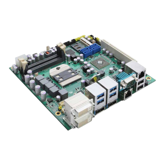
- Page 1 MANO111 Series AMD Embedded R-Series APU Mini ITX SBC User’s Manual...
- Page 2 Axiomtek does not make any commitment to update the information in this manual. Axiomtek reserves the right to change or revise this document and/or product at any time without notice. No part of this document may be reproduced, stored in a retrieval system, or transmitted, in any form or by any means, electronic, mechanical, photocopying, recording, or otherwise, without the prior written permission of Axiomtek Co., Ltd.
-
Page 3: Esd Precautions
Wear a wrist-grounding strap, available from most electronic component stores, when handling boards and components. Trademarks Acknowledgments Axiomtek is a trademark of Axiomtek Co., Ltd. ® Windows is a trademark of Microsoft Corporation. AMI is a trademark of American Megatrend Inc. -
Page 4: Table Of Contents
Table of Contents Disclaimers ..................... ii ESD Precautions ................... iii Chapter 1 Introduction ..........1 Features ....................1 Specifications ..................2 Utilities Supported ................3 Chapter 2 Board and Pin Assignments ....5 Board Dimensions and Fixing Holes ..........5 Board Layout .................. - Page 5 CFast™ Socket (SCN1) ................29 2.4.17 Chapter 3 Hardware Installation ......31 Installing the Processor ..............31 Installing the Memory ............... 34 Chapter 4 Hardware Description ......35 APU (Accelerated Processing Unit) ..........35 BIOS ....................35 System Memory ................. 35 I/O Port Address Map ................
- Page 6 This page is intentionally left blank.
-
Page 7: Chapter 1 Introduction
MANO111 AMD Embedded R-Series APU Mini ITX SBC Chapter 1 Introduction The MANO111 Series supports AMD R-Series APU. The board integrates the Fusion Controller Hub A75 and delivers outstanding system performance through high-bandwidth interfaces, multiple I/O functions for interactive applications and various embedded computing solutions. -
Page 8: Specifications
MANO111 AMD Embedded R-Series APU Mini ITX SBC Specifications AMD R-Series processor. CPU Socket AMD FS1r2 socket. System Chipset AMD A75 FCH. BIOS American Megatrends Inc. BIOS. 32Mbit SPI Flash, DMI, Plug and Play. ... -
Page 9: Utilities Supported
MANO111 AMD Embedded R-Series APU Mini ITX SBC Watchdog Timer 1~255 seconds; up to 256 levels. Form Factor 170 x 170mm Mini ITX form factor. All specifications and images are subject to change without notice. Note Utilities Supported ... - Page 10 MANO111 AMD Embedded R-Series APU Mini ITX SBC This page is intentionally left blank. Introduction...
-
Page 11: Board And Pin Assignments
MANO111 AMD Embedded R-Series APU Mini ITX SBC Chapter 2 Board and Pin Assignments Board Dimensions and Fixing Holes Top View Board and Pin Assignments... - Page 12 MANO111 AMD Embedded R-Series APU Mini ITX SBC Bottom View Board and Pin Assignments...
- Page 13 MANO111 AMD Embedded R-Series APU Mini ITX SBC Side View Board and Pin Assignments...
-
Page 14: Board Layout
MANO111 AMD Embedded R-Series APU Mini ITX SBC Board Layout Top View Board and Pin Assignments... - Page 15 MANO111 AMD Embedded R-Series APU Mini ITX SBC Bottom View Board and Pin Assignments...
-
Page 16: Jumper Settings
And remove jumper clip from 2 jumper pins to open. The following illustration shows how to set up jumper. Before applying power to MANO111 Series, please make sure all of the jumpers are in factory default position. Below you can find a summary table and onboard default settings. - Page 17 MANO111 AMD Embedded R-Series APU Mini ITX SBC Jumper Description Setting CN3 Pin 1: DCD 3-5 close COM4 Data/Power Selection Default: Default: RS-232 Data CN3 Pin 8: RI 4-6 close CN2 Pin 1: DCD 3-5 close COM3 Data/Power Selection Default: RS-232 Data CN2 Pin 8: RI 4-6 close CN1 Pin 1: DCD...
-
Page 18: Com4 Data/Power Selection (Jp2)
MANO111 AMD Embedded R-Series APU Mini ITX SBC 2.3.1 COM4 Data/Power Selection (JP2) The COM4 port has +5V level power capability on DCD and +12V level on RI by setting this jumper. Function Setting Power: Set CN3 pin 1 to +5V level 1-3 close Data: Set CN3 pin 1 to DCD (Default) 3-5 close... -
Page 19: Tpm Normal Operation/Special Commands Selection (Jp6)
MANO111 AMD Embedded R-Series APU Mini ITX SBC 2.3.5 TPM Normal Operation/Special Commands Selection (JP6) Use JP6 for TPM normal operation or special commands selection. Function Setting Normal operation (Default) 1-2 close Special Commands Enable 2-3 close 2.3.6 Auto Power On (JP7) If JP7 is enabled for AC power input, the system will be automatically power on without pressing soft power button. -
Page 20: Lvds Voltage Selection (Jp12 And Jp13)
MANO111 AMD Embedded R-Series APU Mini ITX SBC 2.3.9 LVDS Voltage Selection (JP12 and JP13) The board supports voltage selection for flat panel displays. Use JP12 to set LVDS connector (CN11) pin 1~6 VCCM to +3.3V or +5V voltage level. Use JP13 (optional) to set LVDS connector (CN11) pin 1~6 VCCM to +12V voltage level. -
Page 21: Connectors
MANO111 AMD Embedded R-Series APU Mini ITX SBC Connectors Signals go to other parts of the system through connectors. Loose or improper connection might cause problems, please make sure all connectors are properly and firmly connected. Here is a summary table which shows all connectors on the hardware. Connector Description CN1~3... -
Page 22: Com Connectors (Cn1, Cn2, Cn3 And Cn5)
MANO111 AMD Embedded R-Series APU Mini ITX SBC 2.4.1 COM Connectors (CN1, CN2, CN3 and CN5) These CN1 (for COM2), CN2 (for COM3) and CN3 (for COM4) have +5V level power capability on DCD and 12V level on RI by setting JP4 and JP3 and JP2, respectively (see section 2.3.3 and 2.3.2 and 2.3.1). -
Page 23: Power Connector (Cn4)
MANO111 AMD Embedded R-Series APU Mini ITX SBC 2.4.2 Power Connector (CN4) Steady and sufficient power can be supplied to all components on the board by connecting power connector. Please make sure all components and devices are properly installed before connecting the power connector. External power supply plug fits into this connector in only one orientation. -
Page 24: Sim Card Slot (Cn7)
MANO111 AMD Embedded R-Series APU Mini ITX SBC 2.4.4 SIM Card Slot (CN7) The CN7 is for inserting SIM Card. In order to work properly, the SIM Card must be used together with Mini Card which is inserted to socket CN6. It is mainly used in 3G wireless network application. -
Page 25: Usb Connectors (Cn9 And Cn10)
MANO111 AMD Embedded R-Series APU Mini ITX SBC 2.4.6 USB Connectors (CN9 and CN10) These 2x5 pin wafers (CN9 and CN10) are Universal Serial Bus (USB) connectors. They are for installing versatile USB 2.0 compliant interface peripherals. These connectors are designed with +5V level standby power which can provide power when system is in suspend mode. -
Page 26: Lvds Connector (Cn11)
MANO111 AMD Embedded R-Series APU Mini ITX SBC 2.4.7 LVDS Connector (CN11) This board has a 40-pin connector (CN11) for LVDS LCD interface. It is strongly recommended to use the matching JST SHDR-40VS-B 40-pin connector for LVDS interface. Pin 1~6 VCCM can be set to +3.3V level or +5V level by JP12 (see section 2.3.9). - Page 27 MANO111 AMD Embedded R-Series APU Mini ITX SBC 24-bit single channel 18-bit dual channel Pin Signal Pin Signal Pin Signal Pin Signal 1 VCCM VCCM VCCM VCCM VCCM VCCM VCCM VCCM VCCM VCCM VCCM VCCM N.C. N.C. N.C. N.C. 10 GND 10 GND 11 N.C.
-
Page 28: Lan And Usb Connector (Cn12)
MANO111 AMD Embedded R-Series APU Mini ITX SBC 2.4.8 LAN and USB Connector (CN12) The upper RJ-45 connector (for LAN1) is for high performance plug and play Gigabit ethernet interface which is fully compliant with the IEEE 802.3 standard. Connection can be established by plugging one end of the ethernet cable into this RJ-45 connector and the other end to a 1000/100/10-Base-T hub. -
Page 29: Dual Dvi-D Connector (Cn13)
MANO111 AMD Embedded R-Series APU Mini ITX SBC 2.4.9 Dual DVI-D Connector (CN13) The CN13 is a dual DVI-D connector for digital visual interface display. Signal Signal TMDS3_DATA2# TMDS4_DATA2# TMDS3_DATA2 TMDS4_DATA2 N.C. N.C. N.C. N.C. TMDS3_SCL TMDS4_SCL TMDS3_SDA TMDS4_SDA N.C. N.C. -
Page 30: Usb And Displayport Connectors (Cn14~15 And Cn18~19)
MANO111 AMD Embedded R-Series APU Mini ITX SBC 2.4.10 USB and DisplayPort Connectors (CN14~15 and CN18~19) The CN14 is a high rise stacked USB connector carrying USB 3.0 (port 0 and 1) and USB 2.0 (port 10 and 11). The lower DisplayPort 1 connector (CN18) supports DP++. CN14 Signal CN14 Signal CN14... - Page 31 MANO111 AMD Embedded R-Series APU Mini ITX SBC The CN15 is a high rise stacked USB connector carrying USB 3.0 (port 2 and 3) and USB 2.0 (port 12 and 3). Note that the CN15 can support USB2.0 keyboard/mouse in DOS, but don’t plug in USB storage device when the system boot into OS.
-
Page 32: High Rise D-Sub And Lan Connectors (Cn16 And Cn20)
MANO111 AMD Embedded R-Series APU Mini ITX SBC 2.4.11 High Rise D-Sub and LAN Connectors (CN16 and CN20) The CN16 is a high rise 9-pin D-Sub connector for COM1 featuring +5V level power capability on DCD and +12V level on RI by setting JP5 (see section 2.3.4). If you need COM1 port to support RS-422 or RS-485, please refer to section 2.3.10. -
Page 33: Fan Connectors (Fan1, Fan2 And Fan3)
MANO111 AMD Embedded R-Series APU Mini ITX SBC 2.4.13 FAN Connectors (FAN1, FAN2 and FAN3) Fans are always needed for cooling down CPU and system temperature. The board has three fan connectors. You can find fan speed option(s) at BIOS Setup Utility if either fan is installed. -
Page 34: Front Panel Connector (Jp8)
MANO111 AMD Embedded R-Series APU Mini ITX SBC 2.4.15 Front Panel Connector (JP8) Signal PWRLED+ EXT SPK- N.C. Buzzer PWRLED- N.C. N.C. EXT SPK+ PWRSW- PWRSW+ HW RST- HW RST+ HDDLED- HDDLED+ Power LED Pin 1 connects anode(+) of LED and pin 5 connects cathode(-) of LED. The power LED lights up when the system is powered on. -
Page 35: Serial Ata Connectors (Sata1, Sata2, Sata3 And Sata4)
MANO111 AMD Embedded R-Series APU Mini ITX SBC 2.4.16 Serial ATA Connectors (SATA1, SATA2, SATA3 and SATA4) These Serial Advanced Technology Attachment (Serial ATA or SATA) connectors are for high-speed SATA interfaces. They are computer bus interfaces for connecting to devices such as hard disk drives. - Page 36 MANO111 AMD Embedded R-Series APU Mini ITX SBC This page is intentionally left blank. Board and Pin Assignments...
-
Page 37: Chapter 3 Hardware Installation
MANO111 AMD Embedded R-Series APU Mini ITX SBC Chapter 3 Hardware Installation Installing the Processor Please install the processor step by step as below: Locate the processor socket on the board. Grasp the processor carefully by the edges and place it into the socket vertically. Please ensure that the processor is oriented correctly (see image below). - Page 38 MANO111 AMD Embedded R-Series APU Mini ITX SBC Turn the processor lock into the correct locking orientation as illustrated below. Remove protective cover from the heatsink. Make sure the CPU fan cable is plugged to CPU fan connector. Hardware Installation...
- Page 39 MANO111 AMD Embedded R-Series APU Mini ITX SBC Place heatsink and CPU fan assembly on top of the installed processor. Match the four screws to the fixing holes on the board. Then screw tightly the heatsink and CPU fan assembly onto the board. Be careful not to over tighten the screws as it can damage the processor or the motherboard.
-
Page 40: Installing The Memory
MANO111 AMD Embedded R-Series APU Mini ITX SBC Installing the Memory The board comes with two 204-pin DDR3 SO-DIMM memory sockets with maximum memory capacity up to 16GB. The following image illustrates the location of the sockets: DIMM1 DIMM2 A DDR3 module has the same physical dimensions as a DDR2 SO-DIMM but is notched differently to prevent installation on a DDR2 SO-DIMM socket. -
Page 41: Chapter 4 Hardware Description
7 and Linux environments. The system performance depends on the APU. BIOS The MANO111 Series uses AMI Plug and Play BIOS with a single 32Mbit SPI Flash. System Memory The MANO111 Series supports two 204-pin DDR3 SO-DIMM sockets for a maximum memory of 16GB DDR3 SDRAMs. -
Page 42: I/O Port Address Map
MANO111 AMD Embedded R-Series APU Mini ITX SBC I/O Port Address Map The AMD G-Series APU communicates via I/O ports. Total 1KB port addresses are available for assigning to other devices via I/O expansion cards. Input/output (IO) - [00000000 – 0000000F] Direct memory access controller - [00000000 –... - Page 43 MANO111 AMD Embedded R-Series APU Mini ITX SBC - [000002F8 – 000002FF] Communications Port (COM2) - [00000376 – 00000376] Secondary IDE Channel - [000003B0 – 000003BB] AMD Radeon HD 7520G - [000003B0 – 000003DF] PCI bus - [000003C0 – 000003DF] AMD Radeon HD 7520G - [000003E0 –...
-
Page 44: Interrupt Controller (Irq) Map
MANO111 AMD Embedded R-Series APU Mini ITX SBC Interrupt Controller (IRQ) Map The interrupt controller (IRQ) mapping list is shown as follows: Interrupt request (IRQ) Hardware Description... -
Page 45: Memory Map
MANO111 AMD Embedded R-Series APU Mini ITX SBC Memory Map The memory mapping list is shown as follows: Memory Hardware Description... - Page 46 MANO111 AMD Embedded R-Series APU Mini ITX SBC This page is intentionally left blank. Hardware Description...
-
Page 47: Ami Bios Setup Utility
MANO111 AMD Embedded R-Series APU Mini ITX SBC Chapter 5 AMI BIOS Setup Utility The AMI UEFI BIOS provides users with a built-in setup program to modify basic system configuration. All configured parameters are stored in a flash chip to save the setup information whenever the power is turned off. -
Page 48: Main Menu
MANO111 AMD Embedded R-Series APU Mini ITX SBC Hot Keys Description Left/Right The Left and Right <Arrow> keys allow you to select a setup screen. The Up and Down <Arrow> keys allow you to select a setup screen or ... -
Page 49: Advanced Menu
MANO111 AMD Embedded R-Series APU Mini ITX SBC System Language Use this item to choose the system default language. System Date/Time Use this option to change the system time and date. Highlight System Time or System Date using the <Arrow> keys. Enter new values through the keyboard. Press the <Tab> key or the <Arrow>... - Page 50 MANO111 AMD Embedded R-Series APU Mini ITX SBC ACPI Settings You can use this screen to select options for the ACPI configuration, and change the value of the selected option. A description of the selected item appears on the right side of the screen.
- Page 51 MANO111 AMD Embedded R-Series APU Mini ITX SBC Trusted Computing This screen provides function for specifying the TPM settings. Security Device Support Use this item to enable or disable BIOS support for security device. Current Status Information Display current TPM status information. AMI BIOS Setup Utility...
- Page 52 MANO111 AMD Embedded R-Series APU Mini ITX SBC CPU Configuration This screen shows the CPU information. C6 Mode Enable or disable C6 mode. AMI BIOS Setup Utility...
- Page 53 MANO111 AMD Embedded R-Series APU Mini ITX SBC SATA Configuration In this Configuration menu, you can see the currently installed hardware in the SATA ports. During system boot up, the BIOS automatically detects the presence of SATA devices. AMI BIOS Setup Utility...
- Page 54 MANO111 AMD Embedded R-Series APU Mini ITX SBC USB Configuration You can use this screen to select options for the USB Configuration, and change the value of the selected option. A description of the selected item appears on the right side of the screen.
- Page 55 MANO111 AMD Embedded R-Series APU Mini ITX SBC NCT6627UD Super IO Configuration You can use this screen to select options for the Super IO Configuration, and change the value of the selected option. A description of the selected item appears on the right side of the screen.
- Page 56 MANO111 AMD Embedded R-Series APU Mini ITX SBC NCT6627UD HW Monitor Use this screen for Smart Fan configuration and hardware health status monitoring. This screen displays the temperature of system and CPU, cooling fan speed in RPM and system voltages (VCORE, +12V, +5V and +3.3V). Smart Fan Function Enable or disable Smart Fan function.
-
Page 57: Chipset Menu
MANO111 AMD Embedded R-Series APU Mini ITX SBC Chipset Menu The Chipset menu allows users to change the advanced chipset settings. You can select any of the items in the left frame of the screen to go to the sub menus: ►... - Page 58 MANO111 AMD Embedded R-Series APU Mini ITX SBC South Bridge This screen allows users to configure parameters of South Bridge chipset. OnChip SATA Channel Enable or disable SATA channel. OnChip SATA Type Here are the options: IDE, RAID and AHCI. HD Audio Azalia Device Enable or disable HD audio Azalia device.
- Page 59 MANO111 AMD Embedded R-Series APU Mini ITX SBC North Bridge This screen allows users to configure parameters of North Bridge chipset. For items marked with “”, please press <Enter> for more options. GFX Configuration This option allows users to set GFX Configuration. Memory Information Display system memory information.
-
Page 60: Boot Menu
MANO111 AMD Embedded R-Series APU Mini ITX SBC Boot Menu The Boot menu allows users to change boot options of the system. Setup Prompt Timeout Number of seconds to wait for setup activation key. 65535(0xFFFF) means indefinite waiting. Bootup NumLock State Use this item to select the power-on state for the keyboard NumLock. -
Page 61: Security Menu
MANO111 AMD Embedded R-Series APU Mini ITX SBC Security Menu The Security menu allows users to change the security settings for the system. Administrator Password This item indicates whether an administrator password has been set (installed or uninstalled). User Password This item indicates whether an user password has been set (installed or uninstalled). -
Page 62: Save & Exit Menu
MANO111 AMD Embedded R-Series APU Mini ITX SBC Save & Exit Menu The Save & Exit menu allows users to load your system configuration with optimal or fail-safe default values. Save Changes and Exit When you have completed the system configuration changes, select this option to leave Setup and return to Main Menu. - Page 63 MANO111 AMD Embedded R-Series APU Mini ITX SBC Discard Changes Select this option to quit Setup without making any permanent changes to the system configuration. Select Discard Changes from the Save & Exit menu and press <Enter>. Select Yes to discard changes. ...
- Page 64 MANO111 AMD Embedded R-Series APU Mini ITX SBC This page is intentionally left blank. AMI BIOS Setup Utility...
-
Page 65: Dash User Guide
MANO111 AMD Embedded R-Series APU Mini ITX SBC Chapter 6 Dash User Guide Active DASH Configuration Setup Agent Please check the PXE remote boot is enabled as Figure 1(a), (b) before you use this agent. During the late of BIOS POST, you can press Shift + F10 to launch this agent as Figure 2(a). You need to supply a valid login username and password pair for authentication. - Page 66 MANO111 AMD Embedded R-Series APU Mini ITX SBC Figure 1(b) Chipset Configuration Figure 2(a) Enter into DASH Configuration Setup Agent Dash User Guide...
- Page 67 MANO111 AMD Embedded R-Series APU Mini ITX SBC Figure 2(b) Login to setup Agent Figure 3: Active DASH Configuration Setup Agent Dash User Guide...
- Page 68 MANO111 AMD Embedded R-Series APU Mini ITX SBC BIOS Settings Before you can use text console redirection service provided by Realtek’s DASH controller, you must have a supported BIOS and correct settings. Figure 4 depicts the settings needed in the AMI BIOS. You should always follow the settings shown in the figure for best performance and compatibility.
- Page 69 MANO111 AMD Embedded R-Series APU Mini ITX SBC If you are using AMI BIOS, you need to enable MTCP support and ASF support in the advanced tab within BIOS as Figure 5(a), (b). Without these settings, firmware cannot perform remote control operations and PLDM transfers through SMBus. To use USB redirection service, you should always check the settings of USB controllers.
-
Page 70: Software Installation
MANO111 AMD Embedded R-Series APU Mini ITX SBC SOFTWARE INSTALLATION You must have to install Realtek Management Console under Windows Vista or Windows with version above Vista, such as Windows 7 and Windows Server 2008. These operating systems have a built-in cipher suite called TLS_RSA_WITH_ASE_128_CBC_SHA that is a requirement for DASH implementation. - Page 71 MANO111 AMD Embedded R-Series APU Mini ITX SBC In Manageability page, you can manually set the IP address and the port number associated with a specific DASH enabled computer. Another alternative is to use the discovered IP address and port number, which would be automatically filled into corresponding fields whenever you have completed the discovery phase.
-
Page 72: Remote Control
MANO111 AMD Embedded R-Series APU Mini ITX SBC REMOTE CONTROL In the Remote Control node, you can power on, power off, power reset, or power recycle the DASH capable computer. You can use the check box to specify the boot device during next booting. - Page 73 MANO111 AMD Embedded R-Series APU Mini ITX SBC When Start TCR button is pressed, the remote control function would also be invoked, according to the selected check box in the Redirection After field. This means that you can do text console redirection right now without doing any remote operation, or do it the next time when the computer boots.
- Page 74 MANO111 AMD Embedded R-Series APU Mini ITX SBC FIRMWARE UPDATE Realtek’s console tool can be used to do a remote DASH firmware update regardless of the power state. This means that even in the S5 state (without any operating system), we can do a firmware update process.
- Page 75 MANO111 AMD Embedded R-Series APU Mini ITX SBC FIGURE 12: BULIT-IN WEB SERVER Dash User Guide...
- Page 76 MANO111 AMD Embedded R-Series APU Mini ITX SBC This page is intentionally left blank. Dash User Guide...
-
Page 77: Appendix A Watchdog Timer
MANO111 AMD Embedded R-Series APU Mini ITX SBC Appendix A Watchdog Timer About Watchdog Timer Software stability is major issue in most application. Some embedded systems are not watched by human for 24 hours. It is usually too slow to wait for someone to reboot when computer hangs. -
Page 78: Sample Program
MANO111 AMD Embedded R-Series APU Mini ITX SBC Sample Program Assembly sample code : ;Enable WDT: dx,2Eh al,87h ;Un-lock super I/O dx,al dx,al ;Select Logic device: dx,2Eh al,07h dx,al dx,2Fh al,08h dx,al ;Select WDT function: dx,2Eh al,30h dx,al dx,2Fh al,01h dx,al ;Set Second or Minute : dx,2Eh... -
Page 79: Appendix B Digital I/O
MANO111 AMD Embedded R-Series APU Mini ITX SBC Appendix B Digital I/O About Digital I/O The onboard digital I/O has 8 bits. Each bit can be set to function as input or output by software programming. In default, all pins are pulled high with +5V level (according to main power). The BIOS default settings are 4 inputs and 4 outputs where all of these pins are set to 1. - Page 80 MANO111 AMD Embedded R-Series APU Mini ITX SBC dx,2Eh al,2Ch dx,al dx,2Fh al,02h dx,al Digital Input: ;Programming DI[O..3] as input. dx,2Eh al,07h dx,al dx,2Fh al,08h dx,al dx,2Eh al,30h dx,al dx,2Fh al,04h dx,al ; Set DIO digital input pins value. dx,2Eh al,E4h dx,al dx,2Fh...
- Page 81 MANO111 AMD Embedded R-Series APU Mini ITX SBC dx,2Eh al,E5h dx,al dx,2Fh al,M ;Bit0~3 are DO0~3 state (1 High, 0 Low) ;When M=FF, all DO pins are high ;(see below Note2) Note1: The N has 4 bits. Every bit’s value is either “1” or “0”. "...
- Page 82 MANO111 AMD Embedded R-Series APU Mini ITX SBC This page is intentionally left blank. Digital I/O...
Need help?
Do you have a question about the MANO111 Series and is the answer not in the manual?
Questions and answers