Table of Contents
Advertisement
Quick Links
Advertisement
Table of Contents

Related Manuals for AXIOMTEK MANO321 Series


Summary of Contents for AXIOMTEK MANO321 Series
- Page 1 MANO321 Series ® Intel Celeron Processor J6412 Mini ITX Motherboard User’s Manual...
-
Page 2: Disclaimers
Axiomtek does not make any commitment to update the information in this manual. Axiomtek reserves the right to change or revise this document and/or product at any time without notice. No part of this document may be reproduced, stored in a retrieval system, or transmitted, in any form or by any means, electronic, mechanical, photocopying, recording, or otherwise, without the prior written permission of Axiomtek Co., Ltd. -
Page 3: Esd Precautions
It discharges static electricity from your body. ◼ Wear a wrist-grounding strap, available from most electronic component stores, when handling boards and components. Trademarks Acknowledgments Axiomtek is a trademark of Axiomtek Co., Ltd. ® ® Intel and Celeron are trademarks of Intel Corporation. -
Page 4: Table Of Contents
Table of Contents Disclaimers ...................... ii ESD Precautions ..................... iii Section 1 Introduction ..........1 Features ....................1 Specifications ..................2 Utilities Supported ................. 3 Block Diagram ..................4 Section 2 Board and Pin Assignments ..... 5 Board Layout ..................5 Rear I/O .................... - Page 5 2.4.22 LVDS Backlight Control Header (CN55) ..........22 2.4.23 DC Jack Power Connector (DCJACK1) ..........22 2.4.24 CMOS Battery Connector (BAT1) ............23 2.4.25 SIM Card Slot (SCN1) ................23 2.4.26 M.2 Key B Connector (SCN2) ..............24 Section 3 AMI BIOS Setup Utility ......
- Page 6 This page is intentionally left blank.
-
Page 7: Introduction
MANO321 Mini ITX Motherboard Section 1 Introduction ® The MANO321 Mini-ITX motherboard supports the Intel Celeron Processor J6412. With two DDR4 3200MHz memory support, this motherboard is built to perform best stability and reliability for industrial applications. It comes with one SATA 3.0, four USB 3.2 GEN1, four USB 2.0 and six serial ports (two RS-232/422/485, four RS-232) providing robust storage and I/O options. -
Page 8: Specifications
MANO321 Mini ITX Motherboard Specifications ⚫ ® Intel Elkhart Lake for Intel Celeron® J6412 Processor (TDP:10W). ◼ ⚫ BIOS ◼ AMI BIOS via SPI interface. ⚫ System Memory ◼ Two 260-pin SO-DIMM sockets. ◼ Maximum up to 32GB DDR4 memory. Support 3200MHz. -
Page 9: Utilities Supported
MANO321 Mini ITX Motherboard ⚫ Power Input ◼ One 12V ATX 4-pin power input connector. ◼ One 9~20V DC jack power input connector. Operating Temperature ⚫ 0°C ~ 60°C. ◼ ⚫ Storage Temperature ◼ -40°C ~ 85°C. ⚫ Form Factor ◼... -
Page 10: Block Diagram
MANO321 Mini ITX Motherboard Block Diagram Introduction... -
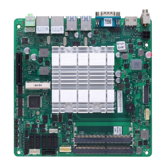
Page 11: Board And Pin Assignments
MANO321 Mini ITX Motherboard Section 2 Board and Pin Assignments Board Layout Top View Board and Pin Assignments... - Page 12 MANO321 Mini ITX Motherboard Bottom View Board and Pin Assignments...
-
Page 13: Rear I/O
MANO321 Mini ITX Motherboard Rear I/O Jumpers/Headers/Connectors 4-pin ATX Power Input Connector (CN26) PCI-Express x4 Slot (CN16) LVDS VDD Select Jumper (JP11) I2C Header (CN27) LVDS Signal Header (CN29) SPI Header (CN12) LVDS Backlight Control Header (CN55) Audio Header (CN52) AT/ATX Power Mode Select Jumper CMOS Battery Connector (BAT1) (JP13) -
Page 14: Jumper Settings
2 jumper pins to close. And remove jumper clip from 2 jumper pins to open. The following illustration shows how to set up jumper. Before applying power to MANO321 Series, please make sure all the jumpers are in factory default position. Below you can find a summary table of all jumpers and onboard default settings. -
Page 15: Com1 Data/Power Select (Jp1)
MANO321 Mini ITX Motherboard Jumper Description Setting 3-5 Close COM Data/Power Select JP1 ~ JP6 Default: RS-232 Data 4-6 Close LVDS VDD Select JP11 1-2 Close Default: +3.3V Level Clear CMOS JP12 1-2 Close Default: Normal Operation AT/ATX Power Mode Select JP13 1-2 Close Default: ATX Mode... -
Page 16: Clear Cmos (Jp12)
MANO321 Mini ITX Motherboard 2.3.4 Clear CMOS (JP12) This jumper allows you to clear the Real Time Clock (RTC) RAM in CMOS. You can clear the CMOS memory of date, time, and system setup parameters by erasing the CMOS RTC RAM data. The onboard button cell battery powers the RAM data in CMOS, which includes system setup information such as system passwords. -
Page 17: Connectors
MANO321 Mini ITX Motherboard Connectors Signals go to other parts of the system through connectors. Loose or improper connection might cause problems, please make sure all connectors are properly and firmly connected. Here is a summary table showing connectors on the hardware. Connector Description COM1 D-Sub Connector... -
Page 18: Com1 D-Sub Connector (Cn1)
MANO321 Mini ITX Motherboard 2.4.1 COM1 D-Sub Connector (CN1) This connector is a standard D-Sub connector for COM1 serial port interface which is selectable for RS-232/422/485 mode by BIOS setting (see section 4.4). The pin assignments of RS-232/422/485 are listed in table below. RS-232 RS-422 RS-485... -
Page 19: Front Panel Header (Cn10)
MANO321 Mini ITX Motherboard 2.4.3 Front Panel Header (CN10) The CN10 is a 2x7-pin (pitch=2.54mm) header. It includes Power-on, Reset, HDD LED and Power LED connections, allowing user to connect the PC case’s front panel switch functions. Signal Signal PWRLED+ EXT SPK- Buzzer PWRLED-... -
Page 20: Spi Header (Cn12)
MANO321 Mini ITX Motherboard 2.4.5 SPI Header (CN12) The CN12 is a 2x5-pin (pitch=2.00mm) header for SPI interface. Signal MISO MOSI 2.4.6 VGA Header (CN14) The CN14 is a 2x8-pin (pitch=2.00mm) header for VGA interface. Signal Signal VGA_RED VGA_GRN VGA_BLUE VGA_5VDDA HSYNC_C VSYNC_C... -
Page 21: Pci-Express X4 Slot (Cn16)
MANO321 Mini ITX Motherboard 2.4.8 PCI-Express x4 Slot (CN16) This motherboard comes with one PCI-Express x4 slot. Signal Signal +12V PRSNT1# +12V +12V RSVD +12V SMCLK SMDAT +3.3V +3.3V 3.3Vaux +3.3V WAKE# PERST# REFCLK+ PETp0 REFCLK- PETn0 PERp0 PRSNT2 PERn0 PETp1 PETn1 PERp1... -
Page 22: Ethernet Ports (Cn17 And Cn18)
MANO321 Mini ITX Motherboard 2.4.9 Ethernet Ports (CN17 and CN18) The motherboard comes with two high performance plug and play Ethernet interfaces (RJ-45) which are fully compliant with the IEEE 802.3 standard. Connection can be established by plugging one end of the Ethernet cable into this RJ-45 connector and the other end to a 1000/100/10-Base-T hub. -
Page 23: Audio Jack (Cn19)
MANO321 Mini ITX Motherboard 2.4.10 Audio Jack (CN19) The motherboard provides HD audio jack for line-out on the rear I/O. Install audio driver, and then attach audio devices to CN19. Pin Color Signal Green Line-out 2.4.11 PCI-Express Mini Card Connector (CN20) The mSATA interface is available through connector CN20. -
Page 24: Usb3.2 Gen1 Stack Ports (Cn21 And Cn22)
MANO321 Mini ITX Motherboard 2.4.12 USB3.2 Gen1 Stack Ports (CN21 and CN22) The motherboard comes with one stacked Universal Serial Bus (compliant with USB 3.2 GEN1) connector on the rear I/O for installing USB peripherals such as a keyboard, mouse, scanner, etc. Signal Signal USB_PWR... -
Page 25: Atx Power Input Connector (Cn26)
MANO321 Mini ITX Motherboard 2.4.15 ATX Power Input Connector (CN26) Steady and sufficient power can be supplied to all components on the board by connecting power connector. Please make sure all components and devices are properly installed before connecting the power connector. External power supply plug fits into the connector in only one orientation. -
Page 26: Lvds Signal Connector (Cn29)
MANO321 Mini ITX Motherboard 2.4.18 LVDS Signal Connector (CN29) The CN29 is a 2x20-pin (pitch=1.00mm) connector for LVDS panel interface Signal Signal LVDS_EDID_SCL LVDS_EDID_SDA LVDS_B_DATA0- LVDS_B_DATA3- LVDS_B_DATA0+ LVDS_B_DATA3+ LVDS_B_DATA1- LVDS_B_CLK- LVDS_B_DATA1+ LVDS_B_CLK+ LVDS_B_DATA2- LVDS_A_DATA0- LVDS_B_DATA2+ LVDS_A_DATA0+ LVDS_A_DATA3- LVDS_A_DATA1- LVDS_A_DATA3+ LVDS_A_DATA1+ LVDS_A_CLK- LVDS_A_DATA2- LVDS_A_CLK+... -
Page 27: Edp Connector (Cn50)
MANO321 Mini ITX Motherboard 2.4.19 eDP Connector (CN50) The embedded DisplayPort (eDP) interface is available through 40-pin connector (CN37), which is compliant with I-PEX-CABLINE II HT1 20143. The eDP is a design to replace internal digital LVDS links in computer monitor panels and TV panels. Signal Signal EDP_HPD... -
Page 28: Sata Power Connector (Cn51)
MANO321 Mini ITX Motherboard 2.4.20 SATA Power Connector (CN51) The CN51 is a 4-pin (pitch=2.54mm) connector for DC +12V and +5V power output. Signal +12V 2.4.21 Audio Header (CN52) The CN52 is a 2x5-pin (pitch=2.00mm) header for convenient connection and control of audio devices. -
Page 29: Cmos Battery Connector (Bat1)
MANO321 Mini ITX Motherboard 2.4.24 CMOS Battery Connector (BAT1) The BAT1 is a 2-pin (pitch=1.25mm) connector for CMOS battery interface. Signal 2.4.25 SIM Card Slot (SCN1) The SCN1 is for inserting SIM Card which is mainly used in wireless network application Signal UIM_PWR UIM_RESET... -
Page 30: Key B Connector (Scn2)
MANO321 Mini ITX Motherboard 2.4.26 M.2 Key B Connector (SCN2) The SCN2 is a M.2 Key B connector. It is suggested to install the M.2 storage module via SATA with 22mm width and 42mm length or the M.2 cellular module via USB 2.0 with 30mm width and 42mm length. -
Page 31: Ami Bios Setup Utility
MANO321 Mini ITX Motherboard Section 3 AMI BIOS Setup Utility The AMI UEFI BIOS provides users with a built-in setup program to modify basic system configuration. All configured parameters are stored in a flash chip to save the setup information whenever the power is turned off. - Page 32 MANO321 Mini ITX Motherboard Hot Keys Description → Left/Right The Left and Right <Arrow> keys allow you to select a setup screen. The Up and Down <Arrow> keys allow you to select a setup screen or sub Up/Down screen. The <Enter>...
-
Page 33: Main Menu
MANO321 Mini ITX Motherboard Main Menu When you first enter the setup utility, you will enter the Main setup screen. You can always return to the Main setup screen by selecting the Main tab. System Time/Date can be set up as described below. -
Page 34: Advanced Menu
MANO321 Mini ITX Motherboard Advanced Menu The Advanced menu also allows users to set configuration of the CPU and other system devices. You can select any of the items in the left frame of the screen to go to the sub menus: ►... - Page 35 MANO321 Mini ITX Motherboard CPU Configuration ⚫ This screen shows CPU information. AMI BIOS Setup Utility...
- Page 36 MANO321 Mini ITX Motherboard Trusted Computing ⚫ This screen provides function for specifying the TPM settings. TPM Device Selection Select TPM device: PTT: Intel ® built-in TPM. Enables PTT in SkuMgr. dTPM: External extended Infineon’s TPM. Disables PTT in SkuMgr. Security Device Support Enable or disable BIOS support for security device.
- Page 37 MANO321 Mini ITX Motherboard Enable or Disable Storage Hierarchy. Endorsement Hierarchy Enable or Disable Endorsement Hierarchy. Physical Presence Spec Version Select to Tell O.S. to support PPI Spec Version 1.2 or 1.3. : Some HCK tests might not support 1.3. Note Device Select TPM 1.2 will restrict support to TPM 1.2 devices, TPM 2.0 will restrict support to TPM 2.0...
- Page 38 MANO321 Mini ITX Motherboard ACPI Settings ⚫ ACPI Sleep State When the suspend button is pressed, the ACPI (Advanced Configuration and Power Interface) sleep state is S3 (Suspend to RAM). Restore AC Power Loss Decide the state of system when power is re-applied after a power failure. Power Off: Keep the power off until the power button is pressed.
- Page 39 MANO321 Mini ITX Motherboard F81966 Super IO Configuration ⚫ You can use this screen to select options for the Super IO Configuration and change the value of the selected option. A description of the selected item appears on the right side of the screen.
- Page 40 MANO321 Mini ITX Motherboard Serial Port 1~2 Configuration ⚫ Serial Port Enable or disable serial port 1~2. Change Settings Select an optimal settings for Super IO device. For serial port 1: Auto IO=3F8h, IRQ=4; IO=3F8h, IRQ=3, 4, 5, 6, 7, 9, 10, 11, 12; IO=2F8h, IRQ=3, 4, 5, 6, 7, 9, 10, 11, 12;...
- Page 41 MANO321 Mini ITX Motherboard Serial Port 3~6 Configuration ⚫ Serial Port Enable or disable serial port 3~6. Change Settings Select an optimal setting for Super IO device. For serial port 3: Auto IO=3E8h, IRQ=7; IO=3E8h, IRQ=3, 4, 5, 6, 7, 9, 10, 11, 12; IO=2E8h, IRQ=3, 4, 5, 6, 7, 9, 10, 11, 12;...
- Page 42 MANO321 Mini ITX Motherboard For serial port 5: Auto IO=2E0h, IRQ=7; IO=3E8h, IRQ=3, 4, 5, 6, 7, 9, 10, 11, 12; IO=2E8h, IRQ=3, 4, 5, 6, 7, 9, 10, 11, 12; IO=2F0h, IRQ=3, 4, 5, 6, 7, 9, 10, 11, 12; IO=2E0h, IRQ=3, 4, 5, 6, 7, 9, 10, 11, 12;...
- Page 43 MANO321 Mini ITX Motherboard Hardware Monitor ⚫ This screen monitors hardware health status. This screen displays the temperature of system and CPU, system voltages (VCCIN, DRAM, +5V, +12V, VCC 3.3V, VSB 3.3V, VBAT). AMI BIOS Setup Utility...
- Page 44 MANO321 Mini ITX Motherboard USB Configuration ⚫ USB Devices Display all detected USB devices. AMI BIOS Setup Utility...
- Page 45 MANO321 Mini ITX Motherboard Network Stack Configuration ⚫ Network Stack Enable or disable UEFI Network Stack. AMI BIOS Setup Utility...
- Page 46 MANO321 Mini ITX Motherboard ⚫ NVMe Configuration Displays information on your M.2 NVME PCIe SSD if installed. AMI BIOS Setup Utility...
- Page 47 MANO321 Mini ITX Motherboard Realtek PCIe GBE Family Controller ⚫ This screen shows the LAN device information. AMI BIOS Setup Utility...
-
Page 48: Chipset Menu
MANO321 Mini ITX Motherboard Chipset Menu The Chipset menu allows users to change the advanced chipset settings. You can select any of the items in the left frame of the screen to go to the sub menus: ► System Agent (SA) Configuration ►... - Page 49 MANO321 Mini ITX Motherboard System Agent (SA) Configuration ⚫ This screen allows users to configure System Agent (SA) parameters. For items marked with “”, please press <Enter> for more options. Graphics Configuration Select to open sub menu for parameters related to graphics configuration. VT-d VT-d capability.
- Page 50 MANO321 Mini ITX Motherboard Graphics Configuration ⚫ Internal Graphics Keep IGFX enabled based on the setup options. GTT Size This option can select the GTT Size. Aperture Size This option can select the Aperture Size. : Above 4GB MMIO BIOS assignment is automatically enabled when selecting 2048MB aperture.
- Page 51 MANO321 Mini ITX Motherboard PCH-IO Configuration ⚫ This screen allows you to set PCH parameters. SATA Configuration SATA device options settings. HD Audio HD Audio Subsystem Configuration Settings. AMI BIOS Setup Utility...
- Page 52 MANO321 Mini ITX Motherboard SATA Configuration ⚫ During system boot up, BIOS automatically detects the presence of SATA devices. In the SATA Configuration menu, you can see all currently installed SATA device(s). SATA Controller(s) Enable or disable the SATA Controller feature. AMI BIOS Setup Utility...
- Page 53 MANO321 Mini ITX Motherboard HD Audio ⚫ Control detection of the HD Audio device. Disabled: HDA will be unconditionally disabled. Enabled: HDA will be unconditionally enabled. AMI BIOS Setup Utility...
- Page 54 MANO321 Mini ITX Motherboard Onboard Device ⚫ Onboard Gigabit LAN 1/2 Enable or disable onboard Gigabit LAN 1/2. Onboard LAN1/LAN2 Option ROM Enable or disable onboard LAN1/LAN2 Option ROM. AMI BIOS Setup Utility...
- Page 55 MANO321 Mini ITX Motherboard LVDS Panel Setting ⚫ LVDS Panel Resolution Allows user to set LVDS Resolution. (Default: 1024x768) LVDS Panel Color Depth Allows user to set LVDS bit rate. (Default: 24 bit) AMI BIOS Setup Utility...
-
Page 56: Security Menu
MANO321 Mini ITX Motherboard Security Menu The Security menu allows users to change the security settings for the system. Administrator Password Set administrator password. User Password Set user password. AMI BIOS Setup Utility... -
Page 57: Boot Menu
MANO321 Mini ITX Motherboard Boot Menu The Boot menu allows users to change boot options of the system. Setup Prompt Timeout Number of seconds to wait for setup activation key. 65535(0xFFFF) means indefinite waiting. Bootup NumLock State Use this item to select the power-on state for the keyboard NumLock. Boot Success Beep Enable or disable beep sound after successful boot. -
Page 58: Save & Exit Menu
MANO321 Mini ITX Motherboard Save & Exit Menu The Save & Exit menu allows users to load your system configuration with optimal or fail-safe default values. Save Changes and Reset Reset the system after saving the changes. Discard Changes and Exit Exit system setup without saving any changes. -
Page 59: Appendix A Watchdog Timer
MANO321 Mini ITX Motherboard Appendix A Watchdog Timer About Watchdog Timer Software stability is major issue in most application. Some embedded systems are not watched by human for 24 hours. It is usually too slow to wait for someone to reboot when computer hangs. - Page 60 MANO321 Mini ITX Motherboard lpFnDll_Get_IO = (LPFNDLLGETIOSPACE)GetProcAddress(GetModuleHandle("diodll.dll"), "GetIoSpaceByte"); lpFnDll_Set_IO = (LPFNDLLSETIOSPACE)GetProcAddress(GetModuleHandle("diodll.dll"), "SetIoSpaceByte"); printf("Input Watch Dog Timer type, 1:Second ; 2:Minute :"); scanf("%d",&unit); printf("\nInput Timer to countdown:"); scanf("%d", &WDTtimer); printf("Start to countdown..."); //==Enter MB Pnp Mode== lpFnDll_Set_IO(0x2e, 0x87); lpFnDll_Set_IO(0x2e, 0x87); lpFnDll_Set_IO(0x2e, 0x07); lpFnDll_Set_IO(0x2f, 0x07);...
-
Page 61: Appendix B Digital I/O
MANO321 Mini ITX Motherboard Appendix B Digital I/O B.1 About Digital I/O The onboard digital I/O has 8 bits. Each bit can be set to function as input or output by software programming. In default, all pins are pulled high with +5V level (according to main power). The BIOS default settings are 4 inputs and 4 outputs. - Page 62 MANO321 Mini ITX Motherboard //MessageBox("Load diodll dll error", "", MB_OK); (hinstLibDLL) lpFnDll_Get_IO = (LPFNDLLGETIOSPACE)GetProcAddress(GetModuleHandle("diodll.dll"), "GetIoSpaceByte"); lpFnDll_Set_IO = (LPFNDLLSETIOSPACE)GetProcAddress(GetModuleHandle("diodll.dll"), "SetIoSpaceByte"); printf("Input Watch Dog Timer type, 1:Second ; 2:Minute :"); scanf("%d",&unit); printf("\nInput Timer to countdown:"); scanf("%d", &WDTtimer); printf("Start to countdown..."); //==Enter MB Pnp Mode== lpFnDll_Set_IO(0x2e, 0x87);...
- Page 63 MANO321 Mini ITX Motherboard lpFnDll_Set_IO(0x2e, 0x89); u89HData = lpFnDll_Get_IO(0x2f); u89HData = clrbit(u89HData, 3); lpFnDll_Set_IO(0x2f, u89HData); while //Get GPIO 8x Status lpFnDll_Set_IO(0x2e, 0x8A); u8AHData = lpFnDll_Get_IO(0x2f); lpFnDll_Set_IO(0x2f, u8AHData); (0x10 & u8AHData) //GPIO84 DI0 status DI0status = GPIO_HIGH; else DI0status = GPIO_LOW; (0x20 &...
Need help?
Do you have a question about the MANO321 Series and is the answer not in the manual?
Questions and answers