
Related Manuals for AXIOMTEK MANO560 Series


Summary of Contents for AXIOMTEK MANO560 Series
- Page 1 MANO560 Series ® Intel Socket 1700 Core i9/ i7/ i5/ i3 Processors Mini ITX Motherboard User’s Manual...
-
Page 2: Disclaimers
Axiomtek does not make any commitment to update the information in this manual. Axiomtek reserves the right to change or revise this document and/or product at any time without notice. No part of this document may be reproduced, stored in a retrieval system, or transmitted, in any form or by any means, electronic, mechanical, photocopying, recording, or otherwise, without the prior written permission of Axiomtek Co., Ltd. -
Page 3: Esd Precautions
It discharges static electricity from your body. ◼ Wear a wrist-grounding strap, available from most electronic component stores, when handling boards and components. Trademarks Acknowledgments Axiomtek is a trademark of Axiomtek Co., Ltd. ® ® Intel and Celeron are trademarks of Intel Corporation. -
Page 4: Table Of Contents
Table of Contents Disclaimers ...................... ii ESD Precautions ..................... iii Section 1 Introduction ..........1 Features ....................2 Specifications ..................2 Utilities Supported ................. 3 Block Diagram ..................4 Section 2 Board and Pin Assignments ....5 Board Layout ..................5 Rear I/O .................... - Page 5 2.4.23 SIM Card Slot (SCN2) ................26 Section 3 AMI BIOS Setup Utility ......27 Starting ....................27 Navigation Keys .................. 27 Main Menu ..................29 Advanced Menu .................. 30 Chipset Menu ..................43 Boot Menu ................... 47 Security Menu ..................48 Save &...
- Page 6 This page is intentionally left blank.
-
Page 7: Introduction
MANO560 Mini ITX Motherboard Section 1 Introduction The MANO560 Mini-ITX motherboard supports the new 14nm 12 Generation Intel ® Core™ i9 / i7/ i5 / i3 and Pentium ® processors in LGA1700 package. Featuring the new Intel ® H610 Express chipset with two DDR4 3200MHz memory support, this motherboard is built to perform best stability and reliability for industrial applications. -
Page 8: Features
MANO560 Mini ITX Motherboard Features LGA1700 Socket for 12 Generation Intel ® Core™ i9/ i7/ i5/ i3 and Pentium ® ⚫ processors (Alder Lake) ⚫ 2 DDR4 3200MHz memory with maximum capacity up to 64 GB ⚫ 1 PCI-Express x16 ⚫... -
Page 9: Utilities Supported
MANO560 Mini ITX Motherboard - One HDMI1.4 connector, resolution up to 4096x2160 @24Hz. - One VGA 15-pin D-Sub connector. - One 24-bit dual channel LVDS and one 8-pin inverter connector. LVDS resolution is max. up to 1920x1200. - One Embedded DisplayPort (eDP) with resolution max. up to 4096x2304 @60Hz;... -
Page 10: Block Diagram
MANO560 Mini ITX Motherboard Block Diagram Introduction... -
Page 11: Board And Pin Assignments
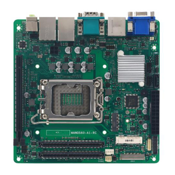
MANO560 Mini ITX Motherboard Section 2 Board and Pin Assignments Board Layout Top View Board and Pin Assignments... - Page 12 MANO560 Mini ITX Motherboard Bottom View Board and Pin Assignments...
-
Page 13: Rear I/O
MANO560 Mini ITX Motherboard Rear I/O Jumpers/Headers/Connectors 4-pin ATX Power Input Connector (CN70) Clear CMOS (JP3) AT/ATX Power Mode Select Jumper PCI-Express x16 Slot (CN20) (JP5) M.2 Key E Socket (CN22) USB 2.0 Header (CN62) PCI-Express Mini Card Connector (CN21) SPI Header (CN81) CPU Fan Header (CN60) COM VDD Select Jumper (JP1) -
Page 14: Jumper Settings
2 jumper pins to close. And remove jumper clip from 2 jumper pins to open. The following illustration shows how to set up jumper. Before applying power to MANO560 Series, please make sure all the jumpers are in factory default position. Below you can find a summary table of all jumpers and onboard default settings. -
Page 15: Com1 Data/Power Select (Jp1)
MANO560 Mini ITX Motherboard Jumper Description Setting 3-5 Close COM Data/Power Select Default: RS-232 Data 4-6 Close Clear CMOS 1-2 Close Default: Normal Operation LVDS VDD Select 1-2 Close Default: +3.3V Level AT/ATX Power Mode Select 1-2 Close Default: ATX Mode 2.3.1 COM1 Data/Power Select (JP1) This is a 3x2-pin (pitch=2.00mm) jumper. -
Page 16: Lvds Vdd Select (Jp4)
MANO560 Mini ITX Motherboard 2.3.3 LVDS VDD Select (JP4) The motherboard supports voltage selection for flat panel displays. Use this 2x3-pin (pitch=2.0mm) jumper to set up VDD power of the LVDS connector. To prevent hardware damage, before connecting please make sure that the input voltage of LVDS panel is correct. -
Page 17: Connectors
MANO560 Mini ITX Motherboard Connectors Signals go to other parts of the system through connectors. Loose or improper connection might cause problems, please make sure all connectors are properly and firmly connected. Here is a summary table showing connectors on the hardware. Connector Description COM1 and COM2 D-Sub Connector... -
Page 18: Com1 And Com2 D-Sub Connector (Cn1)
MANO560 Mini ITX Motherboard 2.4.1 COM1 and COM2 D-Sub Connector (CN1) The CN1 is a double 9-pin D-Sub connector for COM1 and COM2 serial port interfaces on the rear I/O. Only COM1 supports RS-232/422/485 mode. The pin assignments of RS- 232/422/485 are listed in table below. -
Page 19: Sata 3.0 Connectors (Cn7)
MANO560 Mini ITX Motherboard 2.4.3 SATA 3.0 Connectors (CN7) This connector supports the thin Serial ATA cable for primary internal storage device. Signal 2.4.4 USB 3.2 GEN1 Stack Port (CN10) The motherboard comes with one stacked Universal Serial Bus (compliant with USB 3.2 GEN1) connector on the rear I/O for installing USB peripherals such as a keyboard, mouse, scanner, etc. -
Page 20: Lan And Usb 2.0 Connectors (Cn11 And Cn19)
MANO560 Mini ITX Motherboard 2.4.5 LAN and USB 2.0 Connectors (CN11 and CN19) The motherboard supports two Ethernet ports (CN11, CN19): two RJ45 connectors with CN11: Intel® i225-V controller support 10/100/1000/2500Mbps. CN19: Intel® i219-V controller support 10/100/1000 Mbps. The Universal Serial Bus (compliant with USB 2.0) connectors on the rear I/O are for installing USB peripherals such as keyboard, mouse, scanner, etc. -
Page 21: Pci-Express Mini Card Connector (Cn21)
MANO560 Mini ITX Motherboard 2.4.6 PCI-Express Mini Card Connector (CN21) The CN21 complies with PCI-Express Mini Card Spec. V1.2. Signal Signal WAKE# +3.3VAUX +1.5V CLKREQ# UIM_PWR/NC UIM_DAT/NC REFCLK- UIM_CLK/NC REFCLK+ UIM_REST/NC UIM_VPP/NC PERST# PCIE_RX_D- +3.3VAUX PCIE_RX_D+ +1.5V SMB_CLK PCIE_TX_D- SMB_DATA PCIE_TX_D+ USB_D- USB_D+... -
Page 22: Key E Socket (Cn22)
MANO560 Mini ITX Motherboard 2.4.7 M.2 Key E Socket (CN22) The motherboard comes with one M.2 Key E socket (PCIe & USB2.0), The CN22 supports CNVi module. Signal Signal +3.3V_SBY USB_D+ +3.3V_SBY USB_D- M.2_BT_PCMCLK CNVI_WGR_DATA1_D- M.2_BT_PCMRST CNVI_WGR_DATA1_D+ M.2_BT_PCMIN M.2_BT_PCMOUT CNVI_WGR_DATA0_D- CNVI_WGR_DATA0_D+ UART_BT_WAKE- CNVI_WGR_CLK_D-... -
Page 23: Digital I/O Connector (Cn26)
MANO560 Mini ITX Motherboard 2.4.8 Digital I/O Connector (CN26) The CN26 is a 2x5-pin (pitch=2.00mm) connector for digital I/O interface. Signal 2.4.9 LVDS Signal Connector (CN29) The CN29 is a 2x20-pin (pitch=1.00mm) connector for LVDS panel interface Signal Signal LVDS_EDID_SCL LVDS_EDID_SDA LVDS_B_DATA0- LVDS_B_DATA3-... -
Page 24: Atx Power Input Connectors (Cn30 And Cn70)
MANO560 Mini ITX Motherboard 2.4.10 ATX Power Input Connectors (CN30 and CN70) Steady and sufficient power can be supplied to all components on the board by connecting power connector. Please make sure all components and devices are properly installed before connecting the power connector. For better compatibility, we recommend using a standard ATX 24-pin and 4-pin power supply for these connectors. -
Page 25: Displayport1.3 Connector (Cn32)
MANO560 Mini ITX Motherboard 2.4.11 DisplayPort1.3 Connector (CN32) The motherboard comes with DisplayPort interface on the rear I/O. Signal DP_TX0_+ DP_TX0_- DP_TX1_+ DP_TX1_- DP_TX2_+ DP_TX2_- DP_TX3_+ DP_TX3_- DP_AUX+ DP_AUX- DP_HPD +3.3V 2.4.12 HDMI1.4 Connector (CN33) The HDMI (High-Definition Multimedia Interface) is a compact digital interface which can transmit high-definition video and high-resolution audio over a single cable. -
Page 26: Vga Connector (Cn34)
MANO560 Mini ITX Motherboard 2.4.13 VGA Connector (CN34) The CN34 is a high rise 15-pin D-Sub connector which is commonly used for VGA display. This VGA interface configuration can be configured via software utility. Signal Signal Green Blue DDC DATA Horizontal Sync Vertical Sync DDC CLK... -
Page 27: Audio Header (Cn52)
MANO560 Mini ITX Motherboard 2.4.15 Audio Header (CN52) The CN52 is a 2x5-pin (pitch=1.27mm) header for convenient connection and control of audio devices. Signal Signal LINE_IN_L LINE_IN_R SPKOUT_L SPKOUT_R 2.4.16 LVDS Backlight Control Header (CN55) The CN55 is an 8-pin (pitch=1.25mm) header for LVDS backlight control interface. Signal +12V +12V... -
Page 28: Fan Headers (Cn60 And Cn61)
MANO560 Mini ITX Motherboard 2.4.17 Fan Headers (CN60 and CN61) The motherboard has two fan headers. The fan cable and connector may be different according to the fan manufacturer. Connect the fan cable to the connector while matching the black wire to pin#1.CN60 and CN61 both support Smart FAN function. CN60: CPU fan header, 4-pin (pitch=2.54mm) Signal FANPVOUT... -
Page 29: Front Panel Header (Cn80)
MANO560 Mini ITX Motherboard 2.4.19 Front Panel Header (CN80) The CN80 is a 2x7-pin (pitch=2.54mm) header. It includes Power-on, Reset, HDD LED and Power LED connections, allowing user to connect the PC case’s front panel switch functions. Signal Signal PWRLED+ EXT SPK N.C. -
Page 30: Spi Header (Cn81)
MANO560 Mini ITX Motherboard 2.4.20 SPI Header (CN81) The CN81 is a 9-pin (pitch=2.00mm) connector for SPI interface. Signal MISO MOSI 2.4.21 Audio Jack (CN82) The motherboard provides HD audio jack on the rear I/O. Install audio driver, and then attach audio devices to CN82. -
Page 31: Key B Socket (Scn1)
MANO560 Mini ITX Motherboard 2.4.22 M.2 Key B Socket (SCN1) The SCN1 is a M.2 Key B connector. It is suggested to install the M.2 storage module via SATA with 22mm width and 42mm length or the M.2 cellular module via USB 2.0 with 30mm width and 42mm length. -
Page 32: Sim Card Slot (Scn2)
MANO560 Mini ITX Motherboard 2.4.23 SIM Card Slot (SCN2) The SCN2 is for inserting SIM Card which is mainly used in wireless network application. Signal UIM_PWR UIM_RST UIM_CLK DATA Board and Pin Assignments... -
Page 33: Ami Bios Setup Utility
MANO560 Mini ITX Motherboard Section 3 AMI BIOS Setup Utility The AMI UEFI BIOS provides users with a built-in setup program to modify basic system configuration. All configured parameters are stored in a flash chip to save the setup information whenever the power is turned off. - Page 34 MANO560 Mini ITX Motherboard Hot Keys Description → Left/Right The Left and Right <Arrow> keys allow you to select a setup screen. The Up and Down <Arrow> keys allow you to select a setup screen or sub Up/Down screen. The <Enter>...
-
Page 35: Main Menu
MANO560 Mini ITX Motherboard Main Menu When you first enter the setup utility, you will enter the Main setup screen. You can always return to the Main setup screen by selecting the Main tab. System Time/Date can be set up as described below. -
Page 36: Advanced Menu
MANO560 Mini ITX Motherboard Advanced Menu The Advanced menu also allows users to set configuration of the CPU and other system devices. You can select any of the items in the left frame of the screen to go to the sub menus: ►... - Page 37 MANO560 Mini ITX Motherboard ⚫ Connectivity Configuration The CNVi (Connectivity Integration) is a proprietary connectivity interface by Intel for Wi- Fi and Bluetooth radios to lower costs and simplify their wireless modules. CNVi Mode This option configures Connectivity. 1. Auto Detection: If Discrete solution is discovered it will be enabled by default. 2.
- Page 38 MANO560 Mini ITX Motherboard ⚫ CPU Configuration This screen shows CPU information. Intel (VMX) Virtualization Technology Enable or disable Intel Virtualization Technology. When enabled, a VMM (Virtual Machine Mode) can utilize the additional hardware capabilities. It allows a platform to run multiple operating systems and applications independently, hence enabling a single computer system to work as several virtual systems.
- Page 39 MANO560 Mini ITX Motherboard ⚫ SATA Configuration During system boot up, BIOS automatically detects the presence of SATA devices. In the SATA Configuration menu, you can see all currently installed SATA device(s). SATA Controller(s) Enable or disable the SATA Controller feature. AMI BIOS Setup Utility...
- Page 40 MANO560 Mini ITX Motherboard ⚫ Trusted Computing This screen provides function for specifying the TPM settings. TPM Device Selection Select TPM device: PTT: Intel ® built-in TPM. Enables PTT in SkuMgr. dTPM: External extended Infineon’s TPM. Disables PTT in SkuMgr. Security Device Support Enable or disable BIOS support for security device.
- Page 41 MANO560 Mini ITX Motherboard ⚫ ACPI Settings ACPI Sleep State When the suspend button is pressed, the ACPI (Advanced Configuration and Power Interface) sleep state is S3 (Suspend to RAM). S3 Video Repost On enabling, Video Option ROM will be dispatched during S3 resume. Restore AC Power Loss Decide the state of system when power is re-applied after a power failure.
- Page 42 MANO560 Mini ITX Motherboard ⚫ F81966 Super IO Configuration You can use this screen to select options for the Super IO Configuration and change the value of the selected option. A description of the selected item appears on the right side of the screen.
- Page 43 MANO560 Mini ITX Motherboard ⚫ Serial Port 1 Configuration Serial Port Enable or disable serial port 1. Change Settings Select an optimal setting for Super IO device. Auto IO=3F8h, IRQ=4; IO=3F8h, IRQ=3, 4, 5, 6, 7, 9, 10, 11, 12; IO=2F8h, IRQ=3, 4, 5, 6, 7, 9, 10, 11, 12;...
- Page 44 MANO560 Mini ITX Motherboard ⚫ Serial Port 2~4 Configuration Serial Port Enable or disable serial port 2~4. Change Settings Select an optimal setting for Super IO device. For serial port 2: Auto IO=2F8h, IRQ=3; IO=3F8h, IRQ=3, 4, 5, 6, 7, 9, 10, 11, 12; IO=2F8h, IRQ=3, 4, 5, 6, 7, 9, 10, 11, 12;...
- Page 45 MANO560 Mini ITX Motherboard ⚫ Hardware Monitor This screen monitors hardware health status. This screen displays the temperature of system and CPU, cooling fans speed in RPM and system voltages (VCCIO, CPU SA, +5V and +12V). AMI BIOS Setup Utility...
- Page 46 MANO560 Mini ITX Motherboard ⚫ Smart Fan Mode Configuration This screen allows you to configure Smart Fan mode. You can use Smart Fan function to control CN60 and CN61. Smart Fan Function Enable or disable Smart Fan. Fan 1 Smart Fan Control Select Smart Fan operating mode.
- Page 47 MANO560 Mini ITX Motherboard ⚫ USB Configuration USB Devices Display all detected USB devices. AMI BIOS Setup Utility...
- Page 48 MANO560 Mini ITX Motherboard ⚫ Network Stack Configuration Network Stack Enable or disable UEFI Network Stack. IPv4/IPv6 PXE Support Enable or disable IPv4 PXE boot support. If disabled, IPv4/IPv6 PXE boot support will not be available. IPv4/IPv6 HTTP Support Enable or disable IPv4/IPv6 HTTP boot support. If disabled, IPv4/IPv6 HTTP boot support will not be available.
-
Page 49: Chipset Menu
MANO560 Mini ITX Motherboard Chipset Menu The Chipset menu allows users to change the advanced chipset settings. You can select any of the items in the left frame of the screen to go to the sub menus: ► PCH-IO Configuration ►... - Page 50 MANO560 Mini ITX Motherboard ⚫ PCH-IO Configuration This screen allows you to set PCH parameters. HD Audio Control detection of the HD Audio device. Disabled: HDA will be unconditionally disabled. Enabled: HDA will be unconditionally enabled. Auto: HDA will be enabled if present, disabled otherwise. ErP Control When ErP is enabled, system meets ErP requirement.
- Page 51 MANO560 Mini ITX Motherboard Onboard Device ⚫ Onboard LAN 1/2 Enable or disable onboard LAN 1/2. AMI BIOS Setup Utility...
- Page 52 MANO560 Mini ITX Motherboard RTD213x eDP-LVDS ⚫ IGD Flat Panel Allows user to set LVDS resolution. (Default: 1024x768) - LVDS signal divided into 1CH and 2CH. - 1CH: 1 Channel only support resolution up to 1366x768. Note - 2CH: 2 Channel support resolution higher than 1366x768. LVDS Output Allows user to set LVDS bit rate.
-
Page 53: Boot Menu
MANO560 Mini ITX Motherboard Boot Menu The Boot menu allows users to change boot options of the system. ⚫ Setup Prompt Timeout Number of seconds to wait for setup activation key. 65535(0xFFFF) means indefinite waiting. ⚫ Full Screen Logo Display. Enable or disable full screen logo display feature. -
Page 54: Security Menu
MANO560 Mini ITX Motherboard Security Menu The Security menu allows users to change the security settings for the system. ⚫ Administrator Password Set administrator password. ⚫ User Password Set user password. ► Secure Boot AMI BIOS Setup Utility... - Page 55 MANO560 Mini ITX Motherboard Secure Boot ⚫ Secure Boot is a security standard to help ensure that devices will only boot using software trusted by original equipment manufacturers (OEMs). When the computer starts, this firmware checks the signature of every boot software, including UEFI firmware drivers (also called option Rom), EFI applications, and operating systems.
-
Page 56: Save & Exit Menu
MANO560 Mini ITX Motherboard Save & Exit Menu The Save & Exit menu allows users to load your system configuration with optimal or fail-safe default values. ⚫ Discard Changes and Exit Exit system setup without saving any changes. ⚫ Save Changes and Reset Reset the system after saving the changes. -
Page 57: Appendix A Watchdog Timer
MANO560 Mini ITX Motherboard Appendix A Watchdog Timer About Watchdog Timer Software stability is major issue in most application. Some embedded systems are not watched by human for 24 hours. It is usually too slow to wait for someone to reboot when computer hangs. - Page 58 MANO560 Mini ITX Motherboard lpFnDll_Get_IO = (LPFNDLLGETIOSPACE)GetProcAddress(GetModuleHandle("diodll.dll"), "GetIoSpaceByte"); lpFnDll_Set_IO = (LPFNDLLSETIOSPACE)GetProcAddress(GetModuleHandle("diodll.dll"), "SetIoSpaceByte"); printf("Input Watch Dog Timer type, 1:Second ; 2:Minute :"); scanf("%d",&unit); printf("\nInput Timer to countdown:"); scanf("%d", &WDTtimer); printf("Start to countdown..."); //==Enter MB Pnp Mode== lpFnDll_Set_IO(0x2e, 0x87); lpFnDll_Set_IO(0x2e, 0x87); lpFnDll_Set_IO(0x2e, 0x07); lpFnDll_Set_IO(0x2f, 0x07);...
-
Page 59: Appendix B Digital I/O
MANO560 Mini ITX Motherboard Appendix B Digital I/O B.1 About Digital I/O The onboard digital I/O has 8 bits. Each bit can be set to function as input or output by software programming. In default, all pins are pulled high with +5V level (according to main power). The BIOS default settings are 4 inputs and 4 outputs. - Page 60 MANO560 Mini ITX Motherboard //MessageBox("Load diodll dll error", "", MB_OK); (hinstLibDLL) lpFnDll_Get_IO = (LPFNDLLGETIOSPACE)GetProcAddress(GetModuleHandle("diodll.dll"), "GetIoSpaceByte"); lpFnDll_Set_IO = (LPFNDLLSETIOSPACE)GetProcAddress(GetModuleHandle("diodll.dll"), "SetIoSpaceByte"); printf("Input Watch Dog Timer type, 1:Second ; 2:Minute :"); scanf("%d",&unit); printf("\nInput Timer to countdown:"); scanf("%d", &WDTtimer); printf("Start to countdown..."); //==Enter MB Pnp Mode== lpFnDll_Set_IO(0x2e, 0x87);...
- Page 61 MANO560 Mini ITX Motherboard lpFnDll_Set_IO(0x2e, 0x89); u89HData = lpFnDll_Get_IO(0x2f); u89HData = clrbit(u89HData, 3); lpFnDll_Set_IO(0x2f, u89HData); while //Get GPIO 8x Status lpFnDll_Set_IO(0x2e, 0x8A); u8AHData = lpFnDll_Get_IO(0x2f); lpFnDll_Set_IO(0x2f, u8AHData); (0x10 & u8AHData) //GPIO84 DI0 status DI0status = GPIO_HIGH; else DI0status = GPIO_LOW; (0x20 &...
- Page 62 MANO560 Mini ITX Motherboard This page is intentionally left blank. Digital I/O...
-
Page 63: Appendix Cbios Update
MANO560 Mini ITX Motherboard Appendix C BIOS Update With the BIOS-Flasher utility you can easily update motherboard BIOS without having to enter operating system. In this appendix you may learn how to do it in just a few steps. Please read and follow the instructions below carefully. - Page 64 MANO560 Mini ITX Motherboard After booting up, press <F12> to enter the BIOS update screen. Then press <F12> again to enter next screen. Now you can see ini figure below, the "fs0" is the detected USB device. If multiple USB flash drives or hard drives are connected, there will be several optional devices such as "fs1", "fs2"...
- Page 65 MANO560 Mini ITX Motherboard Choose the new BIOS file, then press “Y”. The update will take a few minutes, do not turn off the power or interrupt the update process. Please wait until the utility completes the entire BIOS update process. The following screen will appear once the update is completed.
Need help?
Do you have a question about the MANO560 Series and is the answer not in the manual?
Questions and answers