Table of Contents
Advertisement
Quick Links
Advertisement
Table of Contents

Related Manuals for AXIOMTEK MANO840


Summary of Contents for AXIOMTEK MANO840
- Page 1 MANO840 ® Intel Bay Trail SoC CPU Mini ITX Motherboard User’s Manual...
-
Page 2: Disclaimers
Axiomtek does not make any commitment to update the information in this manual. Axiomtek reserves the right to change or revise this document and/or product at any time without notice. No part of this document may be reproduced, stored in a retrieval system, or transmitted, in any form or by any means, electronic, mechanical, photocopying, recording, or otherwise, without the prior written permission of Axiomtek Co., Ltd. -
Page 3: Esd Precautions
Wear a wrist-grounding strap, available from most electronic component stores, when handling boards and components. Trademarks Acknowledgments Axiomtek is a trademark of Axiomtek Co., Ltd. ® Windows is a trademark of Microsoft Corporation. AMI is a trademark of American Megatrend Inc. -
Page 4: Conventions Used In This Manual
Conventions Used in This Manual To make sure that you perform certain tasks properly, take note of the following symbols used throughout this manual. Information to prevent injury to yourself when trying to complete a task. Warning Information to prevent damage to the components when trying to complete a task. -
Page 5: Table Of Contents
Table of Contents Disclaimers ..................... ii ESD Precautions ................... iii Conventions Used in This Manual ............... iv Chapter 1 Introduction ..........1 Features ....................2 Specifications ..................2 Utilities Supported ................3 Block Diagram ..................4 Chapter 2 Board and Pin Assignments ....5 Board Layout .................. - Page 6 3.1.1 Placement Direction .................. 19 3.1.2 Screw Holes ....................19 System Memory ................. 20 3.2.1 Overview ....................20 3.2.2 Memory Configurations ................21 3.3.3 Installing a SO-DIMM ................21 3.2.4 Removing a SO-DIMM ................23 Expansion Card ................. 23 3.3.1 Installing an Expansion Card..............
-
Page 7: Chapter 1 Introduction
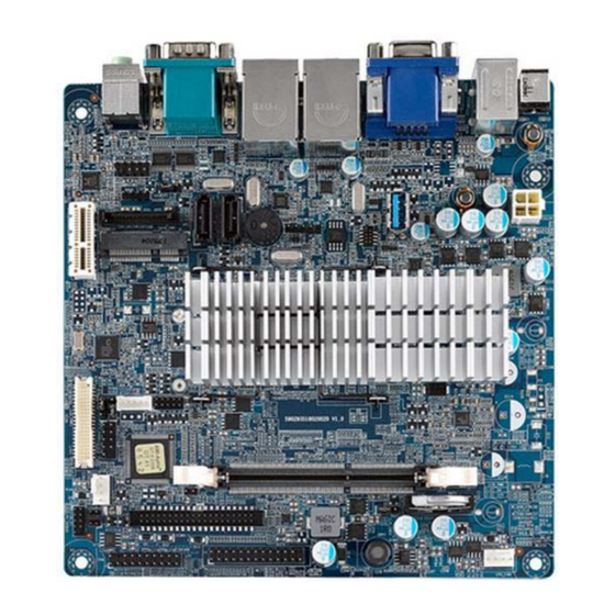
The motherboard has onboard CPU Intel Celeron™ J1900 Quad core 2.42GHz. MANO840 has rich I/O connectivity with PS/2, COM port, Dual LAN, USB port and audio jack integrated in a standard 170mm x 170mm Mini ITX form factor. These motherboards also support dual display for LVDS, HDMI and VGA. -
Page 8: Features
MANO840 Mini ITX Motherboard Features ® Intel Celeron™ J1900 SoC processor 1 DDR3L 1333/1066MHz up to 8GB 1 PCI-Express x1 slot 1 USB 3.0 and 5 USB 2.0 supported 2 SATA 2.0 supported 6 COM ports supported ... -
Page 9: Utilities Supported
MANO840 Mini ITX Motherboard Hardware Monitoring Detect CPU/system temperature, voltage and fan speed. Watchdog Timer 1~255 seconds; up to 255 levels. Power Management ACPI (Advanced Configuration and Power Interface). Form Factor Mini ITX form factor. -
Page 10: Block Diagram
MANO840 Mini ITX Motherboard Block Diagram Introduction... -
Page 11: Board And Pin Assignments
MANO840 Mini ITX Motherboard Chapter 2 Board and Pin Assignments Board Layout Rear Panel I/O Board and Pin Assignments... -
Page 12: Jumper Settings
And remove jumper clip from 2 jumper pins to open. The following illustration shows how to set up jumper. Before applying power to MANO840 Series, please make sure all of the jumpers are in factory default position. Below you can find a summary table and onboard default settings. -
Page 13: Clear Cmos (Clr_Cmos)
MANO840 Mini ITX Motherboard 2.3.1 Clear CMOS (CLR_CMOS) This jumper allows you to clear the Real Time Clock (RTC) RAM in CMOS. You can clear the CMOS memory of date, time, and system setup parameters by erasing the CMOS RTC RAM data. The onboard button cell battery powers the RAM data in CMOS, which includes system setup information such as system passwords. -
Page 14: Com Ri/+5V/+12V Select (Com_Ri)
MANO840 Mini ITX Motherboard 2.3.4 COM RI/+5V/+12V Select (COM_RI) This jumper allows you to select the power mode of COM port. Function Setting +12V 1-2 close RI (Default) 3-4 close 5-6 close 2.3.5 SATA DOM Power Select (SATA_P7) This jumper allows you to select the power mode of SATA DOM. -
Page 15: Connectors
MANO840 Mini ITX Motherboard Connectors Signals go to other parts of the system through connectors. Loose or improper connection might cause problems, please make sure all connectors are properly and firmly connected. Here is a summary table which shows connectors on the hardware. -
Page 16: Rear Panel Connectors
MANO840 Mini ITX Motherboard 2.4.1 Rear Panel Connectors DC_IN. This inlet is for 12V DC inlet. PS/2 mouse port (green). This port is for a PS/2 mouse. PS/2 keyboard port (purple). This port is for a PS/2 keyboard. VGA port. This 15-pin VGA port connects to a VGA monitor. -
Page 17: Digital I/O Connector (Dio)
MANO840 Mini ITX Motherboard System fan interface is available through SYS_FAN, see table below. Signal +12V SENSE Do not forget to connect the fan cables to the fan connectors. Insufficient air flow inside the system may damage the motherboard components. -
Page 18: Atx Power Connector (Atx12V)
MANO840 Mini ITX Motherboard Hard Disk Drive Activity LED (Pin 1-3 HDLED) This 2-pin connector is for the HDD Activity LED. Connect the HDD Activity LED cable to this connector. The IDE LED lights up or flashes when data is read from or written to the HDD. -
Page 19: Lvds Connector (Lvds)
MANO840 Mini ITX Motherboard 2.4.7 LVDS Connector (LVDS) The connector is for 24-bit dual channel LVDS panel. Signal Signal LCD_VDD LCD_VDD LCD_VDD LCD_VDD TXO0- TXE0- TXO0+ TXE0+ TXO1- TXE1- TXO1+ TXE1+ TXO2- TXE2- TXO2+ TXE2+ TXOC- TXEC- TXOC+ TXEC+ DDC_CLK... -
Page 20: Lcd Inverter Connector (Lvdspw)
MANO840 Mini ITX Motherboard 2.4.8 LCD Inverter Connector (LVDSPW) The connector is for the control of internal LVDS brightness. Signal +12V ENBKL Signal Description: For inverter with adjustable backlight function, it is possible to control the LCD brightness through the PWM signal. -
Page 21: Speaker Connector (Spkr)
MANO840 Mini ITX Motherboard 2.4.10 Speaker Connector (SPKR) This connector supports speaker signal. Signal SPK-LL- SPK-LL+ SPK-RR- SPK-RR+ 2.4.11 SATA Connectors (SATA1 and SATA2) These connectors support SATA 2.0 and are for the Serial ATA signal cables for Serial ATA hard disk drives. -
Page 22: Usb 2.0 Connector (F_Usb)
MANO840 Mini ITX Motherboard 2.4.12 USB 2.0 Connector (F_USB) This connector is for USB 2.0 port. Connect the optional USB module cable to this connector then install the module to a slot opening at the back of the system chassis. -
Page 23: Com Connector (Jcom3-1)
MANO840 Mini ITX Motherboard 2.4.14 COM Connector (JCOM3-1) This connector is for four serial ports (COM3~COM6). Connect the serial port module cable to this connector then install the module to a slot opening at the back of the system chassis. - Page 24 MANO840 Mini ITX Motherboard This page is intentionally left blank. Board and Pin Assignments...
-
Page 25: Chapter 3 Hardware Installation
MANO840 Mini ITX Motherboard Chapter 3 Hardware Installation Take note of the following precautions before you install motherboard components or change any motherboard settings. Unplug the power cord from the wall socket before touching any component. Use a grounded wrist strap or touch a safely grounded object or a metal... -
Page 26: System Memory
MANO840 Mini ITX Motherboard Place this side towards the rear of the chassis. System Memory 3.2.1 Overview The motherboard comes with one 204-pin Double Data Rate 3 Low voltage (DDR3L) Small Outline Dual Inline Memory Modules (SO-DIMM) socket. A DDR3L module has the same physical dimensions as a DDR SO-DIMM but has a 204-pin footprint compared to the 204-pin DDR2 DIMM. -
Page 27: Memory Configurations
MANO840 Mini ITX Motherboard 3.2.2 Memory Configurations You may install 1GB, 2GB, 4GB and 8GB non-ECC DDR3L SO-DIMM into the SO-DIMM socket using the memory configurations in this section. If you installed over 4GB memory module, the system may detect less than 3GB of total memory because of address space allocation for other critical functions. - Page 28 MANO840 Mini ITX Motherboard Align a SO-DIMM on the socket such that the notch on the SO-DIMM matches the break on the socket. DDR3L SO-DIMM notch Unlocked retaining clip Firmly insert the SO-DIMM into the socket until the retaining clips snap back in place and the SO-DIMM is properly seated.
-
Page 29: Removing A So-Dimm
MANO840 Mini ITX Motherboard 3.2.4 Removing a SO-DIMM Simultaneously press the retaining clips downward to unlock the SO-DIMM. Remove the SO-DIMM from the socket. Unlocked retaining clip Support the SO-DIMM lightly with your fingers when pressing the retaining clips. The SO-DIMM might get damaged when it flips out with extra force. -
Page 30: Configuring An Expansion Card
MANO840 Mini ITX Motherboard 3.3.2 Configuring an Expansion Card After installing the expansion card, configure it by adjusting the software settings. Turn on the system and change the necessary BIOS settings, if any. See Chapter 5 for information on BIOS setup. -
Page 31: Chapter 4 Hardware Description
Make sure all correct settings are arranged for your installed microprocessor to prevent the CPU from damages. BIOS The MANO840 Series uses AMI Plug and Play BIOS with a single 64Mb SPI Flash. System Memory The MANO840 Series supports one 204-pin DDR3L SO-DIMM socket for maximum memory capacity up to 8GB DDR3L SDRAMs. -
Page 32: I/O Port Address Map
MANO840 Mini ITX Motherboard I/O Port Address Map ® The Intel Celeron J1900 SoC processor communicates via I/O ports. Total 1KB port addresses are available for assigning to other devices via I/O expansion cards. Hardware Description... - Page 33 MANO840 Mini ITX Motherboard Hardware Description...
-
Page 34: Interrupt Controller (Irq) Map
MANO840 Mini ITX Motherboard Interrupt Controller (IRQ) Map The interrupt controller (IRQ) mapping list is shown as follows: Hardware Description... - Page 35 MANO840 Mini ITX Motherboard Hardware Description...
- Page 36 MANO840 Mini ITX Motherboard Hardware Description...
- Page 37 MANO840 Mini ITX Motherboard Hardware Description...
- Page 38 MANO840 Mini ITX Motherboard Hardware Description...
- Page 39 MANO840 Mini ITX Motherboard Hardware Description...
- Page 40 MANO840 Mini ITX Motherboard Hardware Description...
-
Page 41: Memory Map
MANO840 Mini ITX Motherboard Memory Map The memory mapping list is shown as follows: Hardware Description... - Page 42 MANO840 Mini ITX Motherboard This page is intentionally left blank. Hardware Description...
-
Page 43: Ami Bios Setup Utility
MANO840 Mini ITX Motherboard Chapter 5 AMI BIOS Setup Utility The AMI UEFI BIOS provides users with a built-in setup program to modify basic system configuration. All configured parameters are stored in a flash chip to save the setup information whenever the power is turned off. - Page 44 MANO840 Mini ITX Motherboard Hot Keys Description Left/Right The Left and Right <Arrow> keys allow you to select a setup screen. The Up and Down <Arrow> keys allow you to select a setup screen or Up/Down sub-screen. The <Enter> key allows you to display or change the setup option listed for a Enter particular setup item.
-
Page 45: Main Menu
MANO840 Mini ITX Motherboard Main Menu When you first enter the setup utility, you will enter the Main setup screen. You can always return to the Main setup screen by selecting the Main tab. System Time/Date can be set up as described below. -
Page 46: Advanced Menu
MANO840 Mini ITX Motherboard Advanced Menu Launch PXE OpROM Enable or disable the boot ROM function of the onboard LAN chip when the system boots The Advanced menu also allows users to set configuration of the CPU and other system devices. - Page 47 MANO840 Mini ITX Motherboard ACPI Settings You can use this screen to select options for the ACPI configuration, and change the value of the selected option. A description of the selected item appears on the right side of the screen.
- Page 48 MANO840 Mini ITX Motherboard RTC Wake Settings Wake system with Fixed Time Enable or disable system wake on alarm even. When enabled, system will wake upon the hr/min/sec specified. AMI BIOS Setup Utility...
- Page 49 MANO840 Mini ITX Motherboard CPU Configuration This screen shows the CPU information. AMI BIOS Setup Utility...
- Page 50 MANO840 Mini ITX Motherboard SATA Configuration In this Configuration menu, you can see the currently installed hardware in the SATA ports. During system boot up, the BIOS automatically detects the presence of SATA devices. SATA Mode Determine how SATA controller(s) operate. Operation mode options are Disabled, IDE Mode and AHCI Mode.
- Page 51 MANO840 Mini ITX Motherboard Intel IGD SWSCI OpRegion LCD Panel Type This option allows you to select the type of LCD panel connected to the motherboard’s built-in graphics chip. AMI BIOS Setup Utility...
- Page 52 MANO840 Mini ITX Motherboard USB Configuration You can use this screen to select options for the USB Configuration, and change the value of the selected option. A description of the selected item appears on the right side of the screen.
- Page 53 MANO840 Mini ITX Motherboard Super IO Configuration You can use this screen to select options for the Super IO Configuration, and change the value of the selected option. A description of the selected item appears on the right side of the screen.
- Page 54 MANO840 Mini ITX Motherboard H/W Monitor Use this screen for Smart Fan configuration and hardware health status monitoring. This screen displays the temperature of system and CPU, cooling fan speed in RPM and system voltages (CPU VCORE, 5V, 5VSB, 12V and 3.3V).
- Page 55 MANO840 Mini ITX Motherboard TXE Configuration Enable or disable TXE firmware. AMI BIOS Setup Utility...
- Page 56 MANO840 Mini ITX Motherboard Trusted Computing Security Device Support Enable or disable BIOS support for security device. AMI BIOS Setup Utility...
- Page 57 MANO840 Mini ITX Motherboard DIO Configuration Allow user to check digital input 1~4 port state and set digital output 5~8 port setting. EUP Function AMI BIOS Setup Utility...
-
Page 58: Chipset Menu
MANO840 Mini ITX Motherboard Chipset Menu The Chipset menu allows users to change the advanced chipset settings. You can select any of the items in the left frame of the screen to go to the sub menus: ► North Bridge ►... - Page 59 MANO840 Mini ITX Motherboard North Bridge This screen is for North Bridge configuration. DVMT Total Gfx Mem When set to Max Mode, the graphics driver will reserve a Max. of system memory as graphics memory, according to system and graphics requirement...
- Page 60 MANO840 Mini ITX Motherboard South Bridge LAN 1/2 Controller Enable or disable onboard LAN1/LAN2 controller. Azalia HD Audio Enable or disable onboard HD Audio controller. Azalia Internal HDMI Codec Enable or disable onboard Audio internal HDMI controller. Resume from LAN1/2 Enable or disable resume from LAN1/LAN2 function.
-
Page 61: Boot Menu
MANO840 Mini ITX Motherboard Boot Menu The Boot menu allows users to change boot options of the system. Operation System Select Select which OS would be installed. Configuration options are Windows 7 or other OS, Windows 8.x, Windows 8.x with CSM and Manual. - Page 62 MANO840 Mini ITX Motherboard Boot Mode Select This item could be set to Legacy or UEFI. Set Boot Priority Set boot device priority by BIOS setting. AMI BIOS Setup Utility...
-
Page 63: Security Menu
MANO840 Mini ITX Motherboard Security Menu The Security menu allows users to change the security settings for the system. Administrator Password Set setup administrator password. User Password Set user password. AMI BIOS Setup Utility... -
Page 64: Save & Exit Menu
MANO840 Mini ITX Motherboard Save & Exit Menu The Save & Exit menu allows users to load your system configuration with optimal or fail-safe default values. Save Changes and Exit Exit system setup after saving the changes. Discard Changes and Exit Exit system setup without saving the changes.
Need help?
Do you have a question about the MANO840 and is the answer not in the manual?
Questions and answers