
Related Manuals for AXIOMTEK MANO500 Series


Summary of Contents for AXIOMTEK MANO500 Series
- Page 1 MANO500 Series ® Intel Socket 1151 Core i7/ i5/ i3 Processors Mini ITX Motherboard User’s Manual...
- Page 2 Axiomtek does not make any commitment to update the information in this manual. Axiomtek reserves the right to change or revise this document and/or product at any time without notice. No part of this document may be reproduced, stored in a retrieval system, or transmitted, in any form or by any means, electronic, mechanical, photocopying, recording, or otherwise, without the prior written permission of Axiomtek Co., Ltd.
-
Page 3: Esd Precautions
It discharges static electricity from your body. Wear a wrist-grounding strap, available from most electronic component stores, when handling boards and components. Trademarks Acknowledgments Axiomtek is a trademark of Axiomtek Co., Ltd. ® ® Intel and Celeron are trademarks of Intel Corporation. -
Page 4: Table Of Contents
Table of Contents Disclaimers ...................... ii ESD Precautions ..................... iii Chapter 1 Introduction ..........1 Features ....................1 Specifications ..................2 Utilities Supported ................. 3 Block Diagram ..................4 Chapter 2 Board and Pin Assignments ....5 Board Layout ..................5 Rear I/O .................... - Page 5 2.4.20 Fan Connectors (CPU_FAN1 and SYS_FAN1) ........23 2.4.21 SIM Card Slot (SIM1) ................23 2.4.22 SATA 3.0 Connectors (SATA1~SATA3) ............. 23 Chapter 3 Hardware Description ......25 Microprocessors .................. 25 BIOS....................25 System Memory .................. 25 Chapter 4 AMI BIOS Setup Utility ......27 Starting ....................
- Page 6 This page is intentionally left blank.
-
Page 7: Chapter 1 Introduction
MANO500 Mini ITX Motherboard Chapter 1 Introduction The MANO500 is a Mini-ITX motherboard which supports the new 14nm 6 Generation ® ® ® Core™ i7/ i5/ i3, Pentium Intel and Celeron processors in LGA1151 package. Featuring the ® new Intel H110 /Q170 Express chipset with two DDR4 2133MHz memory support, this motherboard is built to perform best stability and reliability for industrial applications. -
Page 8: Specifications
MANO500 Mini ITX Motherboard Specifications ® ® Core™ i7/ i5/ i3, Pentium LGA1151 Socket for 6 and 7 Generation Intel ® Celeron processors. Chipset ® Intel H110/Q170. BIOS AMI BIOS via SPI interface System Memory ... -
Page 9: Utilities Supported
MANO500 Mini ITX Motherboard Power Input One ATX power input connector. One 12V ATX power input connector for CPU Power. Operating Temperature 0°C ~60°C. Storage Temperature -20°C ~60°C. Form Factor Mini ITX (6.7” x 6.7”, 17.0cm x 17.0cm). All specifications and images are subject to change without notice. -
Page 10: Block Diagram
MANO500 Mini ITX Motherboard Block Diagram Introduction... -
Page 11: Board And Pin Assignments
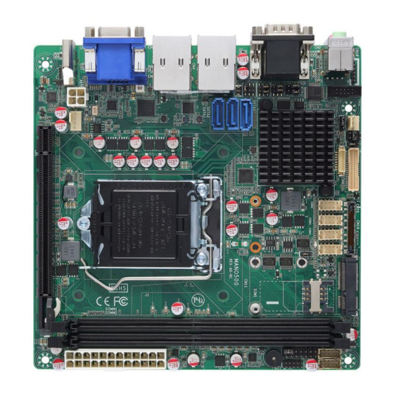
MANO500 Mini ITX Motherboard Chapter 2 Board and Pin Assignments Board Layout Board and Pin Assignments... - Page 12 MANO500 Mini ITX Motherboard Board and Pin Assignments...
-
Page 13: Rear I/O
MANO500 Mini ITX Motherboard Rear I/O Jumpers/Headers/Connectors Keyboard and Mouse Header (CN18) COM1 Data/Power Select Jumper (JP6) Front Audio Header (CN16) eDP Connector (CN19) PCI-Express Mini Card Connector Clear CMOS Jumper (JP1) (CN11) System Fan Connector (SYS_FAN1) SIM Card Slot (SIM1) DDR4 LONG-DIMM Sockets (DIMM1, LVDS VDD Select Jumper (JP7) DIMM2) -
Page 14: Jumper Settings
And remove jumper clip from 2 jumper pins to open. The following illustration shows how to set up jumper. Before applying power to MANO500 Series, please make sure all of the jumpers are in factory default position. Below you can find a summary table of all jumpers and onboard default settings. -
Page 15: Clear Cmos (Jp1)
MANO500 Mini ITX Motherboard Jumper Description Setting Clear CMOS 1-2 Close Default: Normal Operation AT/ATX Power Mode Select 1-2 Close Default: ATX Mode 1-2 Close COM1 RS-232/422/485 Mode Select 3-5, 4-6 Close Default: RS-232 3-5, 4-6 Close CN7 Pin 1: DCD 3-5 Close COM1 Data/Power Select Default: RS-232 Data... -
Page 16: Com1 Rs-232/422/485 Mode Select (Jp3, Jp4, Jp5)
MANO500 Mini ITX Motherboard 2.3.3 COM1 RS-232/422/485 Mode Select (JP3, JP4, JP5) Use these jumpers (3x2-pin p=2.54mm) to set COM1 port to operate in RS-232, RS-422 or RS-485 communication mode. Function Setting JP3 1-2 close RS-232 mode JP4 3-5, 4-6 close (Default) JP5 3-5, 4-6 close JP3 3-4 close... -
Page 17: Connectors
MANO500 Mini ITX Motherboard Connectors Signals go to other parts of the system through connectors. Loose or improper connection might cause problems, please make sure all connectors are properly and firmly connected. Here is a summary table showing connectors on the hardware. Connector Description PCI-Express x16 Slot... -
Page 18: Audio Jack (Cn2)
MANO500 Mini ITX Motherboard 2.4.1 Audio Jack (CN2) The motherboard provides HD audio jack on the rear I/O. Install audio driver, and then attach audio devices to CN2. Pin Color Signal Green Line-out Pink MIC-in 2.4.2 LAN and USB 3.0 Connectors (CN3 and CN4) The motherboard comes with two high performance plug and play Ethernet interfaces (RJ-45) which are fully compliant with the IEEE 802.3 standard. -
Page 19: Displayport Connector (Cn5)
MANO500 Mini ITX Motherboard 2.4.3 DisplayPort Connector (CN5) The DisplayPort interface is available through CN5. Signal DP_TX0_P DP_TX0_N DP_TX1_P DP_TX1_N DP_TX2_P DP_TX2_N DP_TX3_P DP_TX3_N DP_AUXP DP_AUXN DP_HPD +3.3V 2.4.4 VGA Connector (CN6) The CN6 is a high rise 15-pin D-Sub connector which is commonly used for VGA display. This VGA interface configuration can be configured via software utility. -
Page 20: Com Connector (Cn7)
MANO500 Mini ITX Motherboard 2.4.5 COM Connector (CN7) The CN7 is a double-deck DB-9 connector for COM1 and COM2 serial port interfaces where only COM1 is selectable for RS-232/422/485 mode by jumper settings (see section 2.3.3). The pin assignments of RS-232/422/485 are listed in table below. COM1: COM1 RS-232... -
Page 21: Lvds Signal Header (Cn9)
MANO500 Mini ITX Motherboard 2.4.7 LVDS Signal Header (CN9) This motherboard has a 20x2-pin p=1.00mm header for LVDS panel interface. Signal Signal LVDS_B_DATA3- LVDS_B_DATA0- LVDS_B_DATA3+ LVDS_B_DATA0+ LVDS_B_CLK- LVDS_B_DATA1- LVDS_B_ CLK + LVDS_B_DATA1+ LVDS_A_DATA0- LVDS_B_DATA2- LVDS_A_DATA0+ LVDS_B_DATA2+ LVDS_A_DATA1- LVDS_A_DATA3- LVDS_A_DATA1+ LVDS_A_DATA3+ [**] LVDS_PRSNT#(Detect) LVDS_A_DATA2-... -
Page 22: Front Panel Header (Cn10)
MANO500 Mini ITX Motherboard 2.4.8 Front Panel Header (CN10) This is front panel header (7x2-pin p=2.54mm). Signal Power LED+ SPK- BUZZER- Power LED- SPK+ PWR- PWR+ RESET- RESET+ HD LED- HD LED+ : The buzzer on motherboard will be active when pin 2 and pin 4 is connected;... -
Page 23: Pci-Express Mini Card Connector (Cn11)
MANO500 Mini ITX Motherboard 2.4.9 PCI-Express Mini Card Connector (CN11) The CN11 complies with PCI-Express Mini Card Spec. V1.2. Signal Signal WAKE# +3.3VAUX +1.5V +3.3VAUX UIM_PWR UIM_DAT REFCLK- UIM_CLK REFCLK+ UIM_REST UIM_VPP W_DISABLE# PERST# PERN0 +3.3VAUX PERP0 +1.5V SMB_CLK PETN0 SMB_DATA PETP0 USB_10-... -
Page 24: Msata Slot (Cn12)
MANO500 Mini ITX Motherboard 2.4.10 mSATA Slot (CN12) Signal Signal +3.3VAUX +1.5V PERST# SATA0_RX_DP +3.3VAUX SATA0_RX_DN +1.5V SMB_CLK SATA0_TX_DN SMB_DATA SATA0_TX_DP USB_9- USB_9+ +3.3VAUX +3.3VAUX +1.5V +3.3VAUX Board and Pin Assignments... -
Page 25: Usb 2.0 Wafers (Cn13 And Cn14)
MANO500 Mini ITX Motherboard 2.4.11 USB 2.0 Wafers (CN13 and CN14) These are 5x2-pin p=2.00mm headers for USB 2.0 interface. CN13 Signal CN13 Signal USB5- USB6- USB5+ USB6+ CN14 Signal CN14 Signal USB7- USB8- USB7+ USB8+ 2.4.12 GPIO Header (CN15) This header (5x2-pin p=2.54mm) is for digital I/O interface. -
Page 26: Front Audio Header (Cn16)
MANO500 Mini ITX Motherboard 2.4.13 Front Audio Header (CN16) This is front audio header (5x2-pin p=2.00mm) for convenient connection and control of audio devices. Signal Signal MIC_IN LINE_IN_L LINE_IN_R AUD_OUT_L AUD_OUT_R 2.4.14 LVDS Backlight Control Header (CN17) This is an 8x1-pin p=1.25mm header for LVDS backlight control interface. Signal +12V +12V... -
Page 27: Edp Connector (Cn19)
MANO500 Mini ITX Motherboard 2.4.16 eDP Connector (CN19) Signal Signal EMB_HPD EDP_TXN3C EDP_TXP3_C EDP_TXN2_C EDP_TXP2_C EDP_TXN1_C EDP_TXP1_C EDP_TXN0_C EDP_TXP0_C EMB_AUXP EMB_AUXN VSS_EDP_AMOLED +3.3V VCC_EDP_BKLT VSS_EDP_AMOLED EDP_BKLTCTL EDP_BKLTEN VCC_EDP_BKLT +3.3V ISH_I2C0_SCL_R ISH_I2C0_SDA_R +3.3V CN19 is co-layout with LVDS signal header (CN9); they can’t be accessed simultaneously. -
Page 28: Power Input Connectors (Atx1 And Atx2)
MANO500 Mini ITX Motherboard 2.4.18 Power Input Connectors (ATX1 and ATX2) Steady and sufficient power can be supplied to all components on the board by connecting power connector. Please make sure all components and devices are properly installed before connecting the power connector. External power supply plug fits into this connector in only one orientation. -
Page 29: Fan Connectors (Cpu_Fan1 And Sys_Fan1)
MANO500 Mini ITX Motherboard 2.4.20 Fan Connectors (CPU_FAN1 and SYS_FAN1) This motherboard has two fan connectors. Find fan speed option(s) of CPU_FAN1 at BIOS Setup Utility: Advanced\HW Monitor\PC Health Status. CPU_FAN1 (4x1-pin p=2.54mm): Signal +12V FAN Speed Detection FAN Speed Control SYS_FAN1 (3x1-pin p=2.54mm): Signal +12V... - Page 30 MANO500 Mini ITX Motherboard This page is intentionally left blank. Board and Pin Assignments...
-
Page 31: Chapter 3 Hardware Description
CPU from damages. BIOS The MANO500 Series uses AMI Plug and Play BIOS with a single SPI Flash. System Memory The MANO500 supports two 288-pin DDR4 LONG-DIMM sockets for maximum memory capacity up to 32GB DDR4 SDRAMs. - Page 32 MANO500 Mini ITX Motherboard This page is intentionally left blank. Hardware Description...
-
Page 33: Ami Bios Setup Utility
MANO500 Mini ITX Motherboard Chapter 4 AMI BIOS Setup Utility The AMI UEFI BIOS provides users with a built-in setup program to modify basic system configuration. All configured parameters are stored in a flash chip to save the setup information whenever the power is turned off. - Page 34 MANO500 Mini ITX Motherboard Hot Keys Description Left/Right The Left and Right <Arrow> keys allow you to select a setup screen. The Up and Down <Arrow> keys allow you to select a setup screen or sub Up/Down screen. The <Enter>...
-
Page 35: Main Menu
MANO500 Mini ITX Motherboard Main Menu When you first enter the setup utility, you will enter the Main setup screen. You can always return to the Main setup screen by selecting the Main tab. System Time/Date can be set up as described below. -
Page 36: Advanced Menu
MANO500 Mini ITX Motherboard Advanced Menu The Advanced menu also allows users to set configuration of the CPU and other system devices. You can select any of the items in the left frame of the screen to go to the sub menus: ►... - Page 37 MANO500 Mini ITX Motherboard ACPI Settings ACPI Sleep State Select the ACPI (Advanced Configuration and Power Interface) sleep state. Configuration options are Suspend Disabled and S3 (Suspend to RAM). The S3 (Suspend to RAM) option selects ACPI sleep state the system will enter when suspend button is pressed. AMI BIOS Setup Utility...
- Page 38 MANO500 Mini ITX Motherboard CPU Configuration This screen shows CPU information, and you can change the value of the selected option. Hyper-threading Enable or disable Hyper-threading Technology, which allows a single physical processor to multitask as multiple logical processors. When disabled, only one thread per enabled core is enabled.
- Page 39 MANO500 Mini ITX Motherboard SATA Configuration During system boot up, the BIOS automatically detects the presence of SATA devices. In the SATA Configuration menu, you can see the currently installed hardware in the SATA ports. SATA Controller(s) Enable or disable the SATA Controller feature. The default is Enabled. AMI BIOS Setup Utility...
- Page 40 MANO500 Mini ITX Motherboard SATA Mode Selection Determine how SATA controller(s) operate. Operation mode options are: AHCI (Advanced Host Controller Interface) RAID (for Chipset Q170 only) PCH-FW Configuration This screen displays ME Firmware information. AMT Configuration (for Chipset Q170 only) Use this screen to configure AMT parameters.
- Page 41 MANO500 Mini ITX Motherboard AMT BIOS Features Enable or disable Active Management Technology BIOS features. The default is Enabled. USB Configuration USB Devices Display all detected USB devices. AMI BIOS Setup Utility...
- Page 42 MANO500 Mini ITX Motherboard IT8786 Super IO Configuration You can use this screen to select options for the Super IO Configuration, and change the value of the selected option. A description of the selected item appears on the right side of the screen.
- Page 43 MANO500 Mini ITX Motherboard Hardware Monitor This screen monitors hardware health status. This screen displays the temperature of system and CPU, cooling fans speed in RPM and system voltages (VCC_CPU, VCC_DDR, +12V, +5V and +3.3V). AMI BIOS Setup Utility...
- Page 44 MANO500 Mini ITX Motherboard Smart Fan Function This screen allows you to select CPU fan mode. CPU FAN This item allows you to select the fan speed option(s) of CPU_FAN1 (See Section 2.4.20) which can be set to Full on, Automatic mode and Manual Mode. AMI BIOS Setup Utility...
- Page 45 MANO500 Mini ITX Motherboard Automatic mode Follow super I/O IT8786 integrated automatic mode as the below to adjust the fan speed. AMI BIOS Setup Utility...
- Page 46 MANO500 Mini ITX Motherboard Manual Mode Input the Fan Start PWM to start the fan. AMI BIOS Setup Utility...
- Page 47 MANO500 Mini ITX Motherboard Utility Configuration BIOS Flash Utility BIOS flash utility configuration. For more detailed information, please refer to Appendix B. AMI BIOS Setup Utility...
-
Page 48: Chipset Menu
MANO500 Mini ITX Motherboard Chipset Menu The Chipset menu allows users to change the advanced chipset settings. You can select any of the items in the left frame of the screen to go to the sub menus: ► System Agent (SA) Configuration ►... - Page 49 MANO500 Mini ITX Motherboard System Agent (SA) Configuration This screen allows users to configure System Agent (SA) parameters. For items marked with “”, please press <Enter> for more options. Graphics Configuration Open sub menu for parameters related to graphics configuration. Memory Configuration Open sub menu for information related to system memory.
- Page 50 MANO500 Mini ITX Motherboard Graphics Configuration Primary IGFX Boot Display Select the video device which will be activated during POST (Power-On Self Test). The default is Auto. Secondary IGFX Boot Display After selecting other than “auto” on “Primary IGFX Boot Display”, the Secondary IGFX Boot Display will show up and the options are Disabled, HDMI and VGA.
- Page 51 MANO500 Mini ITX Motherboard LVDS Panel Type Select LVDS panel resolution. AMI BIOS Setup Utility...
- Page 52 MANO500 Mini ITX Motherboard Backlight Control This item is for backlight control setting. Selection options are PWM Inverted and PWM Normal. If the LCD brightness regards 5V PWM signal as the brightest, PWM Inverted shall be selected. AMI BIOS Setup Utility...
- Page 53 MANO500 Mini ITX Motherboard Memory Configuration This screen shows the system memory information. AMI BIOS Setup Utility...
- Page 54 MANO500 Mini ITX Motherboard PCH-IO Configuration This screen allows you to set PCH parameters. PCH LAN Controller Enable or disable onboard PCH LAN controller. Wake on LAN After enabling PCH LAN Controller, enabling or disabling integrated LAN to wake the system.
-
Page 55: Security Menu
MANO500 Mini ITX Motherboard Security Menu The Security menu allows users to change the security settings for the system. Administrator Password This item indicates whether an administrator password has been set (installed or uninstalled). User Password This item indicates whether a user password has been set (installed or uninstalled). AMI BIOS Setup Utility... -
Page 56: Boot Menu
MANO500 Mini ITX Motherboard Boot Menu The Boot menu allows users to change boot options of the system. Setup Prompt Timeout Number of seconds to wait for setup activation key. 65535(0xFFFF) means indefinite waiting. Bootup NumLock State Use this item to select the power-on state for the keyboard NumLock. ... -
Page 57: Save & Exit Menu
MANO500 Mini ITX Motherboard Save & Exit Menu The Save & Exit menu allows users to load your system configuration with optimal or fail-safe default values. Save Changes and Exit When you have completed the system configuration changes, select this option to leave Setup and return to Main Menu. - Page 58 MANO500 Mini ITX Motherboard Discard Changes Select this option to quit Setup without making any permanent changes to the system configuration. Select Discard Changes from the Save & Exit menu and press <Enter>. Select Yes to discard changes. Restore Defaults It automatically sets all Setup options to a complete set of default settings when you select this option.
-
Page 59: Appendix A Watchdog Timer
MANO500 Mini ITX Motherboard Appendix A Watchdog Timer About Watchdog Timer Software stability is major issue in most application. Some embedded systems are not watched by human for 24 hours. It is usually too slow to wait for someone to reboot when computer hangs. - Page 60 MANO500 Mini ITX Motherboard This page is intentionally left blank. Watchdog Timer...
-
Page 61: Appendix Bbios Flash Utility
Please read and follow the instructions below carefully. In your USB flash drive, create a new folder and name it “Axiomtek”, see figure below. Copy BIOS ROM file (e.g. MANO500.005) to “Axiomtek” folder. - Page 62 Select the USB drive containing BIOS ROM file you want to update using the <> or <> key. Then press <Enter> to get into “Axiomtek” folder. Now you can see the BIOS ROM file on the screen, press <Enter> to select.
- Page 63 MANO500 Mini ITX Motherboard Please wait while BIOS completes the entire flash update process: erase data, write new data and verify data. 10. When you see the following figure, press <Enter> to finish the update process. After that the system will shut down and restart immediately. BIOS Flash Utility...
Need help?
Do you have a question about the MANO500 Series and is the answer not in the manual?
Questions and answers