
Related Manuals for AXIOMTEK MANO120


Summary of Contents for AXIOMTEK MANO120
- Page 1 MANO120 AMD G-Series T56N 1.65GHz APU With A55E Controller Hub (FCH) Mini-ITX Motherboard User’s Manual...
-
Page 2: Table Of Contents
MANO120 Mini-ITX SBC User’s Manual Contents Safety Information ................iv CHAPTER 1 INTRODUCTION ................ 1 Before you proceed ................1 Motherboard Overview ................ 2 1.2.1 Placement Direction....................2 1.2.2 Screw Holes ......................2 Motherboard Layout ................3 Central Processing Unit (CPU) ............5 System Memory .................. - Page 3 MANO120 Mini-ITX SBC User’s Manual CHAPTER 2 BIOS Setup ................35 BIOS Setup Program ..............35 2.1.1 Legend Box ......................37 2.1.2 List Box ........................37 2.1.3 Sub-menu ......................38 BIOS Menu Screen ................. 39 2.2.1 Main ........................39 2.2.2 Advanced .......................
-
Page 4: Safety Information
MANO120 Mini-ITX SBC User’s Manual Safety Information Electrical safety To prevent electrical shock hazard, disconnect the power cable from the electrical outlet before relocating the system. When adding or removing devices to or from the system, ensure that the power cables for the devices are unplugged before the signal cables are connected. -
Page 5: Technical Support
If a problem arises with your system and no solution can be obtained from the user’s manual, please contact your place of purchase or local distributor. Alternatively, please try the following help resources for further guidance. Visit the Axiomtek website for FAQ, technical guide, BIOS updates, driver updates, and other information: http://www.axiomtek.com... -
Page 6: Packing List
Before you begin installing your single board, please make sure that the following materials have been shipped: 1 x MANO120 Mini ITX Main board 1 x CD-ROM contains the followings: - User’s manual (this manual in PDF file) -... - Page 7 MANO120 Mini-ITX SBC User’s Manual Revision History Revision Revision History Date V 1.0 First release 2012/3/5 Specifications Summary G-Series APU Type AMD G-Series T56N 1.65GHz DC Processor Family AMD G-Series TDP 18W, T shutdown 125℃ Long Life Processor List Package FT1 (BGA) 413 balls p=0.8mm, 19x19 mm...
- Page 8 MANO120 Mini-ITX SBC User’s Manual Chipset Fusion Controller Hub AMD A55E Controller Hub (Hudson-E1) PCIe x4 Gen 2 8 USB 2.0 (4 Rear, 4 Internal) SMBus SATA 5 SATA 3.0 (One support SATADOM) HD Audio support 4 channel, Power Saving, 4 codec Clock Gen.
- Page 9 MANO120 Mini-ITX SBC User’s Manual BIOS BIOS Core BIOS Core AMI EFI BIOS Flash BIOS Flash 16Mb SPI SW RAID SW RAID None Boot up Device Serial ATA Yes (CFast) IDE device USB device Boot from LAN Power Management ACPI ACPI 3.0...
- Page 10 MANO120 Mini-ITX SBC User’s Manual Internal Connector Debug Port HDT header Display LVDS esp. 1, (optional) Inverter LVDS INV 1, 3.3 V Audio Front Panel Amplifier SPDI/F Serial SATA SATA 5 (SATA III 6 Gb/s) SATA power Fan connector System fan connector...
- Page 11 MANO120 Mini-ITX SBC User’s Manual Audio 1 Line-out Phone Jack 1 MIC co-lay 1 jack connector Power Power Connector Power Type AT/ATX Power Requirement +3.3V, +5V, +12V, -12V, 5Vsb GPIO General 8bit Front I/O Display HDMI 1, co-layout with header...
- Page 12 MANO120 Mini-ITX SBC User’s Manual LED Indicator 4; alive, green; dead, red HDD Status 4; access, flash yellow Power on rear IO 1; Blue Expansion Slot Expansion Slot Mini-PCI Express PCIex 4 PCB Physical Feature Dimension 170x 170mm Layer 6 Layer Power Consumption <...
- Page 13 MANO120 Mini-ITX SBC User’s Manual PCB Printing Model name in silkscreen None Revision in silkscreen PCB Color Blue CE mark on PCB WEEE axiomtek PCB part number Version FCC mark on PCB Cert. Compliance Pre-scan for Class B, EN-55022/24 Pre-scan for FCC PART 15, Class B...
-
Page 14: Block Diagram
MANO120 Mini-ITX SBC User’s Manual Block Diagram This chapter describes the main board features and the new technologies it supports... -
Page 15: Chapter 1 Introduction
MANO120 Mini-ITX SBC User’s Manual CHAPTER 1 INTRODUCTION 1.1 Before you proceed Take note of the following precautions before you install motherboard components or change any motherboard settings. Unplug the power cord from the wall socket before touching any component. -
Page 16: Motherboard Overview
MANO120 Mini-ITX SBC User’s Manual 1.2 Motherboard Overview Before you install the motherboard, study the configuration of your chassis to ensure that the motherboard fits into it. Refer to the chassis documentation before installing the motherboard. Make sure to unplug the power cord before installing or removing the motherboard. -
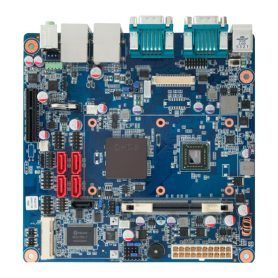
Page 17: Motherboard Layout
MANO120 Mini-ITX SBC User’s Manual 1.3 Motherboard Layout Introduction... - Page 18 MANO120 Mini-ITX SBC User’s Manual Layout Content List Slots Label Function Note CFast Compact Flash socket Rear side MINI_PCIE Mini PCI-E slot 52PIN PCIE PCI E slot 64PIN SODIMM_A1 204-PIN SODIMM slot 1 204-PIN Jumpers Label Function Note CLRTC Clear CMOS1 3 x 1 header, pitch 2.54mm...
-
Page 19: Central Processing Unit (Cpu)
MANO120 Mini-ITX SBC User’s Manual 1.4 Central Processing Unit (CPU) 1.4.1 Connect the CPU Fan cable to the CPU_FAN connector on the motherboard. Do not forget to connect the CPU Fan connector! Hardware monitoring errors can occur if you fail to plug this connector. -
Page 20: System Memory
MANO120 Mini-ITX SBC User’s Manual 1.5 System Memory 1.5.1 DIMM Sockets Location The motherboard comes with one 204-pin Double Data Rate 3 (DDR3) SODIMM sockets. A DDR3 module has the same physical dimensions as a DDR DIMM but has a 204-pin footprint. -
Page 21: Memory Configurations
MANO120 Mini-ITX SBC User’s Manual 1.5.2 Memory Configurations You can install 1GB, 2GB and 4GB DDR3 DIMMs into the SODIMM sockets using the memory configurations in this section. Installing DDR3 DIMM other than the recommended configurations may cause memory sizing error or system boot failure. Use any of the recommended configurations. -
Page 22: Installing A Ddr3 Dimm
MANO120 Mini-ITX SBC User’s Manual 1.5.3 Installing a DDR3 DIMM Make sure to unplug the power supply before adding or removing DIMMs or other system components. Failure to do so may cause severe damage to both the motherboard and the components. -
Page 23: Removing A Ddr3 Dimm
MANO120 Mini-ITX SBC User’s Manual 1.5.4 Removing a DDR3 DIMM Press the two ejector tabs on the slot outward simultaneously, and then pull out the DIMM module. Support the DIMM lightly with your fingers when pressing the ejector tabs. The DIMM might get damaged when it flips out with extra force. -
Page 24: Expansion Slots
MANO120 Mini-ITX SBC User’s Manual 1.6 Expansion Slots In the future, you may need to install expansion cards. The following sub‑sections describe the slots and the expansion cards that they support. Make sure to unplug the power cord before adding or removing expansion cards. -
Page 25: Standard Interrupt Assignments
MANO120 Mini-ITX SBC User’s Manual 1.6.3 Standard Interrupt Assignments * There IRQs are usually available for ISA or PCI device Priority Standard Function System Timer Keyboard Controller Redirect to IRQ#9 IRQ holder for PCI streering* Communications Port (COM1)* IRQ holder for PCI streering*... -
Page 26: Jumpers
MANO120 Mini-ITX SBC User’s Manual 1.7 Jumpers 1.7.1 Clear CMOS (CMOS1) This jumper allows you to clear the Real Time Clock (RTC) RAM in CMOS. You can clear the CMOS memory of date, time, and system setup parameters by erasing the CMOS RTC RAM data. -
Page 27: Com3 Ri/+5V/+12V Selection (Jsetcom3)
MANO120 Mini-ITX SBC User’s Manual 1.7.2 COM3 RI/+5V/+12V Selection (JSETCOM3) +5V (Default) +12V Ring Introduction... -
Page 28: Com4 Ri/+5V/+12V Selection (Jsetcom4)
MANO120 Mini-ITX SBC User’s Manual 1.7.3 COM4 RI/+5V/+12V Selection (JSETCOM4) +5V (Default) +12V Ring Introduction... -
Page 29: Connectors
MANO120 Mini-ITX SBC User’s Manual 1.8 Connectors 1.8.1 Rear Panel Connectors Label Function Description PS/2 mouse The standard PS/2 mouse DIN connector is for a KBMS connector PS/2 mouse. Serial port COM12 D-Sub 9-pin, male connector This port allows Gigabit connection to a Local Area Network (LAN) through a network hub. - Page 30 MANO120 Mini-ITX SBC User’s Manual This port connects a headphone or a speaker. In Line-Out port 4-channel, 6-channel, and 8-channel configuration, AUDIO (Lime) the function of this port becomes Front Speaker Out. Microphone port AUDIO This port connects a microphone.
-
Page 31: Front Panel Audio Connector (Aafp)
MANO120 Mini-ITX SBC User’s Manual 1.8.2 Front Panel Audio Connector (AAFP) This connector is for a chassis-mounted front panel audio I/O module that supports either HD Audio or legacy AC ‘97 (optional) audio standard. Connect one end of the front panel audio I/O module cable to this connector. -
Page 32: Atx Power Connector (Atxpwr)
MANO120 Mini-ITX SBC User’s Manual 1.8.3 ATX Power Connector (ATXPWR) These connectors are for ATX power supply plugs. The power supply plugs are designed to fit these connectors in only one orientation. Find the proper orientation and push down firmly until the connectors completely fit. -
Page 33: At/Atx Mode Select (Pson1)
MANO120 Mini-ITX SBC User’s Manual 1.8.4 AT/ATX Mode Select (PSON1) Introduction... -
Page 34: Lcd Power (Vddsafe) (Jbl3)
MANO120 Mini-ITX SBC User’s Manual 1.8.5 LCD POWER (VDDSAFE) (JBL3) Introduction... -
Page 35: Serial Port Connector (Com3, Com4)
MANO120 Mini-ITX SBC User’s Manual 1.8.6 Serial Port Connector (COM3, COM4). Component type: HEADER 2X5P /2.54mm, w/o Pin10 COM3 COM4 Introduction... -
Page 36: System Panel & Speaker (Jfp1 + Jfp2)
MANO120 Mini-ITX SBC User’s Manual 1.8.7 System Panel & Speaker (JFP1 + JFP2) Component type: HEADER 4x3P /2.54mm Internal PIN7-10 PIN3-6 POWER BT PIN1-10 External PIN9-12 SYS_RESET Introduction... -
Page 37: Ower Led & Key Lock (Jfp3)
MANO120 Mini-ITX SBC User’s Manual ower LED & Key lock (JFP3) 1.8.8 Component type: HEADER 1X5P /2.54mm Introduction... -
Page 38: Inverter Pwr (Jbl1)
MANO120 Mini-ITX SBC User’s Manual 1.8.9 Inverter PWR (JBL1) Component type: WAFER 1x5P / 2.0mm Introduction... -
Page 39: Spi Connector (Cn4)
MANO120 Mini-ITX SBC User’s Manual SPI connector (CN4) 1.8.10 Component type: HEADER 2X4P /2.54mm Introduction... -
Page 40: Spdif Out (Spdif_Out1)
MANO120 Mini-ITX SBC User’s Manual SPDIF OUT (SPDIF_OUT1) 1.8.11 Component type: HEADER 1X4P /2.54mm Introduction... -
Page 41: 18-Bit Lvds Connector (Lvds1)
MANO120 Mini-ITX SBC User’s Manual 1.8.12 18-bit LVDS Connector (LVDS1) Component type: HIROSE DF-13 /40P,1.25mm Introduction... -
Page 42: Amp_R+R-/Amp_L+L- (Cn10)
MANO120 Mini-ITX SBC User’s Manual 1.8.13 AMP_R+R-/AMP_L+L- (CN10) Component type: HEADER 1X4P /2.54mm Introduction... -
Page 43: Serial Ata Connector (Sata1, Sata2)
MANO120 Mini-ITX SBC User’s Manual 1.8.14 Serial ATA Connector (SATA1, SATA2) These connectors are for the Serial ATA signal cables for Serial ATA hard disk drives. SATA1 SATA2 Introduction... - Page 44 MANO120 Mini-ITX SBC User’s Manual Serial ATA Connector (SATA3, SATA4) These connectors are for the Serial ATA signal cables for Serial ATA hard disk drives. SATA3 SATA4 Introduction...
- Page 45 MANO120 Mini-ITX SBC User’s Manual Serial ATA Connector (SATA5) These connectors are for the SATADOM and Serial ATA signal cables for Serial ATA hard disk drives. SATA5 Introduction...
- Page 46 MANO120 Mini-ITX SBC User’s Manual Connect the right-angle side of SATA signal cable to SATA device. Or you may connect the right-angle side of SATA cable to the onboard SATA port to avoid Mechanical conflict with huge graphics cards. ...
-
Page 47: Usb 2.0 Connector (Usb5,6)
MANO120 Mini-ITX SBC User’s Manual 1.8.15 USB 2.0 Connector (USB5,6) These connectors are for USB 2.0 ports. Connect the USB/GAME module cable to any of these connectors, then install the module to a slot opening at the back of the system chassis. - Page 48 MANO120 Mini-ITX SBC User’s Manual USB 2.0 Connector (USB7,8) These connectors are for USB 2.0 ports. Connect the USB/GAME module cable to any of these connectors, then install the module to a slot opening at the back of the system chassis.
-
Page 49: Chapter 2 Bios Setup
MANO120 Mini-ITX SBC User’s Manual CHAPTER 2 BIOS Setup 2.1 BIOS Setup Program This motherboard supports a programmable firmware chip that you can update using the provided utility. Use the BIOS Setup program when you are installing a motherboard, reconfiguring your system, or prompted to “Run Setup.” This section explains how to configure your system using this utility. - Page 50 MANO120 Mini-ITX SBC User’s Manual The Setup program is designed to make it as easy to use as possible. Being a menu-driven program, it lets you scroll through the various sub-menus and make your selections from the available options using the navigation keys.
-
Page 51: Legend Box
MANO120 Mini-ITX SBC User’s Manual 2.1.1 Legend Box The keys in the legend bar allow you to navigate through the various setup menus Key(s) Function Description ← Select Screen ↑↓ Select Item Change Option / Field Enter Go to Sub Screen... -
Page 52: Sub-Menu
MANO120 Mini-ITX SBC User’s Manual Sub-menu 2.1.3 Note that a right pointer symbol appears to the left of certain fields. This pointer indicates that you can display a sub-menu from this field. A sub-menu contains additional options for a field parameter. To display a sub-menu, move the highlight to the field and press <Enter>. -
Page 53: Bios Menu Screen
MANO120 Mini-ITX SBC User’s Manual 2.2 BIOS Menu Screen When you enter the BIOS, the following screen appears. The BIOS menu screen displays the items that allow you to make changes to the system configuration. To access the menu items, press the up/down/right/left arrow key on the keyboard until the desired item is highlighted, then press [Enter] to open the specific menu. - Page 54 MANO120 Mini-ITX SBC User’s Manual 2.2.1.1 Date [Day, xx/ xx/ xxxx] The date format is <week>, <month>, <day>, <year>. 2.2.1.2 Time [xx : xx : xx] The time format is <hour><minute><second>, based on the 24-hour clock. BIOS Setup...
-
Page 55: Advanced
MANO120 Mini-ITX SBC User’s Manual 2.2.2 Advanced BIOS Setup... - Page 56 MANO120 Mini-ITX SBC User’s Manual 2.2.2.1 ACPI Setting BIOS Setup...
- Page 57 MANO120 Mini-ITX SBC User’s Manual 2.2.2.2 CPU Configuration BIOS Setup...
- Page 58 MANO120 Mini-ITX SBC User’s Manual 2.2.2.3 IDE Configuration SATA Port1 SATA Port2 SATA Port3 SATA Port4 SATA Port5 BIOS Setup...
- Page 59 MANO120 Mini-ITX SBC User’s Manual 2.2.2.4 USB Configuration BIOS Setup...
- Page 60 MANO120 Mini-ITX SBC User’s Manual 2.2.2.5 Second Super IO Configuration BIOS Setup...
- Page 61 MANO120 Mini-ITX SBC User’s Manual 2.2.2.6 Super IO Configuration BIOS Setup...
- Page 62 MANO120 Mini-ITX SBC User’s Manual 2.2.2.7 H/W Monitor BIOS Setup...
-
Page 63: Chipset
MANO120 Mini-ITX SBC User’s Manual 2.2.3 Chipset This category displays base memory, extended memory, and total memory detected during POST (Power On Self Test). BIOS Setup... - Page 64 MANO120 Mini-ITX SBC User’s Manual 2.2.3.1 North Bridge BIOS Setup...
- Page 65 MANO120 Mini-ITX SBC User’s Manual 2.2.3.1.1 Memory Configuration BIOS Setup...
- Page 66 MANO120 Mini-ITX SBC User’s Manual 2.2.3.1.2 Node 0 Information BIOS Setup...
- Page 67 MANO120 Mini-ITX SBC User’s Manual 2.2.3.2 North Bridge LVDS Coning Select BIOS Setup...
- Page 68 MANO120 Mini-ITX SBC User’s Manual 2.2.3.3 South Bridge BIOS Setup...
- Page 69 MANO120 Mini-ITX SBC User’s Manual 2.2.3.3.1 SB SATA Configuration BIOS Setup...
- Page 70 MANO120 Mini-ITX SBC User’s Manual 2.2.3.3.2 SB USB Configuration BIOS Setup...
-
Page 71: Boot
MANO120 Mini-ITX SBC User’s Manual 2.2.4 Boot BIOS Setup... -
Page 72: Save & Exit
MANO120 Mini-ITX SBC User’s Manual 2.2.5 Save & Exit BIOS Setup...
Need help?
Do you have a question about the MANO120 and is the answer not in the manual?
Questions and answers