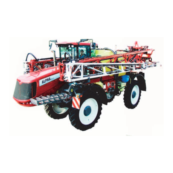
Sign In
Upload
Manuals
Brands
Hardi Manuals
Farm Equipment
ALPHA EVO II EcoDrive
Hardi ALPHA EVO II EcoDrive Manuals
Manuals and User Guides for Hardi ALPHA EVO II EcoDrive. We have
1
Hardi ALPHA EVO II EcoDrive manual available for free PDF download: Instruction Book
Hardi ALPHA EVO II EcoDrive Instruction Book (222 pages)
Brand:
Hardi
| Category:
Farm Equipment
| Size: 27.88 MB
Table of Contents
Table of Contents
3
EU Declaration
9
EU Declaration of Conformity
9
General Safety Instructions
11
Obligations and Liability
11
Comply with the Instruction Book
11
Before First Use of the Sprayer
11
Obligations of the Operator
14
Risks in Handling the Sprayer
15
Disclaimer
15
Organizational Measures
16
Personal Protective Equipment
16
Representation of Safety Symbols
17
Explanation of Symbols
17
Warning Signs on the Sprayer
18
Explanation of Labels
18
Safety and Protection Equipment
19
Safety at Start-Up
19
Faulty Safety Equipment
19
Informal Safety Measures
20
Additional Safety Instructions
20
Operator Training
21
Authorized Persons
21
Safety Measures in Normal Operation
22
Protection Equipment
22
Products Manufacturer Responsibility
22
Residual Energy
23
Possible Dangers
23
Service and Maintenance Work
24
Preventive Measures
24
Design Changes
25
Operator Limitations
25
Spare Parts, Wear Parts and Aids
25
Cleaning and Disposal
26
Environmental Protection
26
Workstation
27
Intended Place for Operator
27
Risks of Non-Compliance
27
If the Safety Information Is Ignored
28
Possible Risks and Dangers
28
Safety Information for Operators
29
General Safety and Accident Prevention
29
Mixture Carried on the Tank
30
Road Transport
30
Hydraulic System
31
Electrical System
31
Use of the Sprayer
32
Field Sprayer Operation
33
Environmental Precautions
33
Service Work Precautions
34
Cleaning
34
Service and Maintenance
35
Description
37
General Info
37
View
37
Identification Plate
38
Data
39
Sprayer Use
40
Lifetime
41
Liquid System
42
Pump
42
Dynamicfluid4 Pressure Regulation
44
Filters
46
Diagram - Liquid System with Optional Extras
51
Diagram - Intelligent Liquid System with Optional Extras
52
TWIN Air Technique
53
General Info
53
Boom
54
Standard Boom Features
54
Engine
56
Rating Plates of Engine and After-Treatment Gas System
56
Exhaust Gas After-Treatment
56
Cabin
58
Description
58
Description of Driver's Seat
59
Control Panel
60
General Description of Operator's Seat
61
Cabin Ceiling Controls
62
Speed Selector and Parking Brake
62
4-Wheels Steering (Standard)
63
Steering Column
63
Aluminium Hydraulic Controls
64
HAZ Boom Hydraulic Function Controls
65
TERRA FORCE Boom Hydraulic Controls
65
Multi-Function Display
67
Transmission
68
Diff-Lock Differential Locking Front/Back
68
Anti-Skid (SAPE)
68
Pneumatic System
69
Pneumatic Diagram (with Optional Equipment)
69
Sprayer Setup
71
Cabin
71
Recommendations before Installing the Filter
71
Install the Filter
71
Unloading the Sprayer from the Truck
72
Accessories
72
Precautions before Putting the Sprayer into Operation
73
Spraying
74
Spraying Pump
74
Fitting the Nozzles
74
Cyclonefilter
74
Boomprime Adjustment
75
Chassis
76
Altering the Track Width
76
Tyres Inflate Pressure
77
Tightening Lug Nuts
77
Operation
79
Driving
79
Starting up and Shutting down the Engine
79
Travelling and Braking
80
Parking Brake
81
Steering - Automatic 4-Wheel Steering Version (Standard)
82
General Information
82
Driving in 2-Wheel Steering
82
Driving in 4-Wheel Steering
83
Driving in Offset 2-Wheel Steering
83
Steering - Automatic 4-WS
84
Genral Info
84
Operation
84
2-Wheel Steering Mode
84
Follower' Mode
85
Steering Axle Mode
85
Manual Mode
86
Slope Counter-Steering Function
87
CRAB" Mode
87
Hydraulic Track Adjustment (Optional)
88
HTA Control Unit Display
88
Transmission and Engine Operation
90
General Info
90
Information Messages
90
Settings Driving Mode
91
Field / Uphill / Downhill Mode
91
Automotive Mode
92
Comfort, Normal, Power Mode
93
Ecodrive Mode
94
Limitation of Travel Speed in Field, Uphill, Downhill Modes
94
Limitation of Travel Speed in Automotive Mode
95
Engine R.P.M. Limitation
96
Inter-Axle Differential Lock (Difflock)
97
Electronic Traction Control (SAPE)
97
Fuel and Adblue Gauges
97
Operation Monitoring
99
Messages Related to Events
99
Error Messages
100
Severity of Engine Defects
101
Exhaust Gas Aftertreatment System with SCR
101
Implementation of the Standstill Regeneration
102
Engine Anti-Stall
103
Engine Overspeed
103
Hydraulic Overheating
103
Hydraulic Oil too Low
104
Battery Voltage too Low
104
Retractable Gangway
104
Cabin
106
Suspension of the Cab (if Fitted)
106
Air Conditioning
106
Operating Modes
106
Pressurization Operating Mode
109
Default Codes
110
Water Valve Calibration
110
General Info
111
Manoeuvring of the Boom
114
End Nozzles (Optional)
114
Filling/Washing Location Requirements
116
Filling of Water
116
Filling through Tank Lid
117
External Filling Device
118
Filling of Rinsing Tank
118
Filling of Clean Water Tank
119
Operating the Turbofiller
121
Filling Powder Chemicals Using the Turbofiller
124
Turbofiller Rinsing
125
Boomprime
126
Boomflush - Manual Cleaning
126
Before Returning to Refill the Sprayer
127
Parking the Sprayer
127
Liquid Fertilizer
127
Operating Limits
128
Cleaning
130
General Info
130
Quick Reference - Cleaning
131
Cleaning the Tank and Liquid System
133
Cleaning and Maintenance of Filters
133
Use of Cleaning Agent
133
Use of Rinsing Tank and Rinsing Nozzles
134
Full Internal Cleaning (Soak Wash)
137
Primeflow - Manual Cleaning
138
Boomflush - Manual Cleaning
138
Technical Residue
138
Using the Drain Valve
138
Pressure Draining
139
Outside Cleaning - Use of External Cleaning Device
139
Maintenance
141
Lubrication
141
General Information
141
Suitable Lubricants
141
Maintenance Intervals
141
Resetting the Maintenance Intervals
141
Recommended Part List
142
Service Intervals
143
Engine
144
Lubricating Oil Level
144
Engine Radiators
144
Coolant
144
Engine Suction System
145
Dry Air Filter
145
Fuel Pre-Filter Draining
146
Fuel Pre-Filter
146
Engine Lubricating Oil
147
Adblue Filter Replacement
148
Cooling System
148
Battery
149
Cabin and Air Conditioning
150
Replacement the Cabin Filter (Category 4)
150
Air Conditioning Compressor
151
Air Conditioning Gas
151
Hydraulic
152
Hydraulic System
152
Hydraulic Filters Replacement
152
Auxiliary Hydraulic Filters
153
Drain the Hydraulic Tank
153
Cleaning the Hydraulic Tank
154
Chassis and Boom
155
HTA Rear Axle Lubrication
155
HTA Front Axle Lubrication
155
Paralift Lubrication
156
LPA5 Central Frame Lubrication
156
TR4 Boom Lubrication
157
RHA Boom Lubrication
157
Tightening Lug Nuts
158
Spraying
159
Suction Filter (if Fitted)
159
Pressure Filter (if Fitted)
159
Cyclonefilter
159
In-Line Filter
160
Nozzle Filter
160
Spraying Circuit
160
Greasing the Pump
160
Spraying Pressure Gauge
161
Compressed Air System
162
Draining Air Tanks
162
Air Compressor
163
Air Pressure Switch Adjustment
164
Occasional Maintenance
165
General Info
165
Lifting and Removing the Pump
165
Pump Valves and Diaphragms Renewal
165
Speed Sensor for Pump
167
Level Indicator Adjustment
167
Feed Pipe Clamp Assembly
168
Feed Pipe Snap-Lock Assembly
168
Nozzle Holder Assembly
168
Nozzle Pipe Assembly
171
Boomprime One-Way Valve
172
Adjustment of 3-Way Valve
173
HAZ Boom
174
Readjustment of Boom - General Info
174
Adjustment of Springs in Centre Section
175
Adjustment of Boom Tilt
176
Horizontal Alignment of Inner Sections
177
Adjustment of Breakaway Section
181
Yaw Damping
181
Alignment of Rubber Pads on Spray Boom
182
TR4 Boom
183
Off-Season Storage
187
After Storage
188
Repair
189
Operational Problems
189
General Info
189
Spraying
190
Hydraulic Functions
190
Transmission
191
Release the Brake
191
Transmission Pump High Pressure Relief Valves
192
Errors Messages
193
Transmission Errors
193
Engine Errors Codes
195
Engine Codes Errors
196
Location of Main Components
200
Main Circuit Fuses and Relays
200
Multifunction Display
202
Side Lights Fuses
202
Fuses Test
203
Engine and Jobcom Fuses
203
Air Compressor Fuse
203
Jobcom with Primeflow
204
Jobcom Connections
204
Direct Activated Hydraulic, DAH, PCB #93Connections
204
Optional Power Supply Connection, out
204
Lightening
205
Hydraulic Track Axle
206
Angular Sensor Faulty
206
Calibrating the Angular Sensor Stops
206
Track Width Calibration
206
Cabin
208
Diagnostic
208
Technical Specifications
211
Characteristics
211
Main Characteristics
211
Overall Dimensions
211
Weight
212
Tyres
212
Accumulator
213
Hydraulic Pressure
213
Air Pressure
213
Air Conditioning
213
Sound Level
213
Identification Plates
214
Cabin
216
Air Conditioning Diagram
217
Advertisement
Advertisement
Related Products
Hardi EVRARD ALPHA 2500
Hardi ALPHA evo EcoDrive TWIN FORCE
Hardi ALPHA evo ALU-TWIN FORCE
Hardi NEPTUN AB820
Hardi ZATURN AG820
Hardi ZATURN AG920
Hardi ZENIT AG750
Hardi ARROW 2000
Hardi AEON CENTURA DELTA FORCE
Hardi AEON CENTURA TWIN FORCE
Hardi Categories
Paint Sprayer
Farm Equipment
Controller
Tractor Accessories
Boom Lifts
More Hardi Manuals
Login
Sign In
OR
Sign in with Facebook
Sign in with Google
Upload manual
Upload from disk
Upload from URL