Table of Contents
Advertisement
Advertisement
Table of Contents

Subscribe to Our Youtube Channel
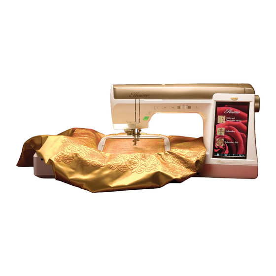
Related Manuals for Baby Lock Ellisimo BLSO


Summary of Contents for Baby Lock Ellisimo BLSO
-
Page 3: Using The Machine Setting Mode Key
LCD SCREEN Using the Machine Setting Mode Key Press to change the default machine settings (needle stop position, embroidery speed, opening display, etc.). To display the different settings screens, press for “Sewing settings”, “General settings” or for “Embroidery settings”. Memo •... - Page 4 Display the program version. “Version 1” shows the program version of the LCD panel, “Version 2” shows the program version of the machine. Memo • The latest version of software is installed in your machine. Check with your local authorized Baby Lock retailer or at “www.babylock.com” for available updates (see page 331).
- Page 5 LCD SCREEN Embroidery settings a Select from among 14 embroidery frame displays (see page 230). b Change the thread color display on the embroidery screen; thread number, color name (see page 229). c When the thread number “#123” is selected, select from six thread brands (see page 229). d Adjust the maximum embroidery speed setting (see page 229).
- Page 6 Basics of Disassembly Main parts Removal of Top cover unit assy 1. Remove the top cover unit assy. 1. → Refer to 3 - 3 "Disassembly of Top cover unit assy". Removal of Accessory table assy 1. Remove the accessory table assy. 1. →...
- Page 7 Basics of Disassembly Main parts Removal of Free arm front cover assy 1. Remove the screw 1 and the screw 2. 2. Remove the hook 1 and the 2 hooks 2, and then remove the free arm front cover assy. 3. →...
- Page 8 Basics of Disassembly Main parts Removal of Face plate assy 1. Remove the face plate screw cap 1. *Key point • Remove the face plate screw cap 1 by using the pin or etc. 2. Open the face plate connector cover 2. 3.
- Page 9 Basics of Disassembly Main parts Removal of Belt cover 1. Remove the upper cover cap 1. *Key point • Remove it while inserting flat-blade screwdriver. in the position of the right figure. 2. Remove the 2 screws 1, and then remove the belt cover 2. *Key point •...
- Page 10 Basics of Disassembly Main parts Removal of Bobbin winder (upper cover assy) 1. Remove the connector 1 from the main PCB assy.. 2. Remove the 3 screw caps 2 from the bobbin winder (upper cover assy.) *Key point • Remove the screw cap 2 by using the pin or etc. 3.
- Page 11 Basics of Disassembly Main parts Removal of Front cover assy 1. Remove the screw 1, and then remove the front cover assy. 1. *Key point • Remove the hook of the front cover while pushing the arrow 2 of the rear cover, and then remove the hook of the front cover while pulling the arrow 3 of the rear cover.
- Page 12 Basics of Disassembly Main parts Removal of Rear cover assy 1. Remove the screw 1, the screw 2 and the 4 screws 3, and then remove the rear cover assy. 1. *Key point • Release the 2 hooks 2 from the base plate assy.. →...
- Page 13 Basics of Disassembly Main parts Removal of Connector cover 1. Remove the connector 1 of the FC jack assy. from the main PCB assy., and then remove the ferrite core 2 from the clip 3. 2. Remove the 2 screws 1, and then remove the connector cover 4. *Key point •...
- Page 14 Basics of Assembly Main parts Attachment of Connector cover 1. Attach the connector cover 1 to the base plate assy. with the 2 screws 1. *Key point • Check that the 2 hooks 2 hang on the base plate assy.. 2.
-
Page 15: Main Parts
Basics of Assembly Main parts Attachment of Rear cover assy 1. Set the rear cover assy. 1 to the arm bed, and then secure it with the 4 screws 1, the screw 2 and the screw 3. *Key point • Check that the 2 hooks 2 hang on the base plate assy.. •... - Page 16 Basics of Assembly Main parts Attachment of Front cover assy 1. Attach the connector 1 of the lead wire assy main-panel to the panel PCB assy. 2. 2. Attach the FFC 3 to the panel PCB assy. 2. *Key point •...
- Page 17 Test Mode Start Test mode and Contents With front cover 1. How to start test mode Turn on the power while pressing the (Start/Stop button) and the (Reverse stich button), then test mode starts (test mode screen is displayed). 2. Contents of test mode Test mode Ref.
-
Page 18: Test Mode
Test Mode Start Test mode and Contents Test mode Ref. Mode Contents of test mode page Display target and actual rotation speed of upper Speed shaft. Running the machine with the maximum electric Power power. Embroidery and utility stitch count. Clearing Memory/Clearing Counter (Able to reset in maintenance) NP Sensor... - Page 19 Test Mode Start Test mode and Contents 3. Check switches and sensors function (Test Mode No.29) State: Current switch or sensor operation. Record: Switch or sensor operating record. (Use in production line) Clear button:Reset the record. (Use in production line) Item: Foot Jack Foot controller jack...
-
Page 20: Touch Panel
Adjustment Touch panel [Adjustment standard] Touch the 5 point in order from 1 to 5, and then “SUCCESS” is displayed. [Adjustment procedure] 1. Turn the power on while pressing the (Start/Stop button), (Reverse stitch button) and (Needle position button). 2. Touch the point (+) in order from 1 to 5. *Key point •... -
Page 21: Timing Belt Tension
Adjustment Timing belt tension [Adjustment standard] 2.5 to 3.5mm slack by pushing the center of the belt with a force of 1.96N (200g). [Adjustment procedure] 1. Remove the covers. See “Procedure 1 to 12 in Main parts in Basics of Disassembly in Chapter 2”. 2. -
Page 22: Motor Belt Tension
Adjustment Motor belt tension [Adjustment standard] 1.5 to 3.5mm slack by pushing the center of the belt with a force of 0.98N (100g). [Adjustment procedure] 1. Remove the covers. See “Procedure 1 to 12 in Main parts in Basics of Disassembly in Chapter 2”. 2. -
Page 23: Fine Tension
Adjustment Fine tension [Adjustment standard] Start test mode, pass the schappe spun thread #60 through tension plate and pull it by tension gauge, then adjust tension must be in 0.04 to 0.05N (4 to 5g). [Adjustment procedure] 1. Remove the front thread guard cover. 2. -
Page 24: Upper Thread Tension
Adjustment Upper thread tension [Adjustment standard] Start test mode, pass the schappe spun thread #60 through tension plate, tension disk,and plate assy., and pull it by tension gauge, then adjust tension must be in 0.33 to 0.41N (34 to 42g). [Adjustment procedure] 1. -
Page 25: Thread Take Up Spring Tension
Adjustment Thread take up spring tension In case replace or disassemble thread take up spring or thread catching case, need to adjust. [Adjustment standard] The tension (0.15 to 0.19N ; 15 to 19g) when pulling the thread take up spring up with the thread to the right above. [Adjustment procedure] 1. - Page 26 Adjustment Thread take up spring tension 6. Through thread inside thread guide wire, then tie thread at the point A (thread take up spring). Pull thread to above with the tension gauge, and check tension when pulling it to the thread guide wire. 7.
-
Page 27: Inner Rotary Hook Assy. (Lower Thread) Tension
Adjustment Inner rotary hook assy. (lower thread) tension [Adjustment standard] Inner rotary hook assy. (lower thread) tension is 0.10 to 0.12N (10 to 12g). [Adjustment procedure] 1. Set the bobbin (the schappe spun thread #60) in the inner rotary hook assy.. 2. - Page 28 Adjustment Upper shaft shutter angle [Adjustment standard] In the test mode “22” buzzer stops, when the base line of the pulley is at the top (0 angle). [Adjustment procedure] 1. Remove the belt cover and the bobbin winder (upper cover assy.). 2.
-
Page 30: Left Base Line Needle Drop
Adjustment Left base line needle drop [Adjustment standard] In the test mode “04”, needle top (left base line) must drop in the right side of “V” groove on needle plate. (See 1 below) [Adjustment procedure] 1. Remove the face plate assy., and the presser foot. 2. -
Page 31: Needle Bar Rising
Adjustment Needle bar rising [Adjustment standard] The right edge of the needle aligns with the outer rotary hook point when raising needle bar up 2.9 to 3.3mm from its lowest position. [Adjustment procedure] 1. Start the test mode, and then select the “04” (3-point needle drop mode). 2. -
Page 32: Needle Bar Height
Adjustment Needle bar height [Adjustment standard] When turn the pulley by hand until the right edge of the needle aligns with the outer rotary hook point, clearance between the top of needle hole and the outer rotary hook point is 1.0 to 1.4mm. [Adjustment procedure] 1. -
Page 33: Needle Threader
Adjustment Needle threader [Adjustment standard] When passing the hook into the needle hole, clearance between the upper edge of the hook and the upper edge of the needle hole is 0mm. [Adjustment procedure] 1. Remove the face plate assy.. 2. Attach the #11 needle. 3. - Page 34 Technical Service Tip! Baby Lock Ellisimo Needle Threader Exchange Procedure: The new advanced needle threader hook that has been added to the Ellisimo has a new spring that was not on other models. Failure to detach spring prior to removing the threader hook will cause damage to the spring.
- Page 35 3. In the case that the parts separate, please assemble as shown © Tacony Corp 10/2008...
- Page 36 4. While reattaching the Threader Hook Assemble. Make sure metal stud is positioned into plastic track. 5. Reconnect spring to metal plate (with use of a small hook tool). © Tacony Corp 10/2008...
-
Page 38: Needle Clearance Left/Right
Adjustment Needle clearance left/right [Adjustment standard] In the test mode “04”, clearance between needle top and outer rotary hook point is same at the base line of both left and right. [Adjustment procedure] 1. Remove the face plate assy., the presser foot, the needle plate A and the needle plate B, and then remove the inner rotary hook. -
Page 39: Inner Rotary Hook Bracket Position
Adjustment Inner rotary hook bracket position [Adjustment standard] Clearance (overlap) between inner rotary hook point and bracket spring must be 1.6 to 1.8mm. [Adjustment procedure] 1. Remove the needle plate B. 2. Set the inner rotary hook in the outer rotary hook assy.. 3. -
Page 40: Presser Bar Height And Parallelism
Adjustment Presser bar height and parallelism [Adjustment standard] The clearance between the needle plate A and bottom surface of the presser foot is 7.0 to 7.5mm. Presser foot parallel with feed dog hole. [Adjustment procedure] 1. Remove the face plate assy.. 2. - Page 41 Adjustment Cloth pressure setting [Adjustment standard] In the test mode “02”, set the cloth pressure: 0mm and 3mm. [Adjustment procedure] 1. Attach the J presser foot. 2. Start the test mode, and then select the “02” (Fabric thickness setting / PF PM Adjust mode). 3.
- Page 42 Adjustment Knee lifter position [Adjustment standard] In the test mode “02”, set the maximum and minimum knee lifter position. [Adjustment procedure] 1. Start the test mode, and then select the “02” (Fabric thickness setting / PF PM Adjust mode). 2. Turn the pulley by hand and down the feed dog lower than the needle plate A. 3.
- Page 43 Adjustment Feed dog height and parallelism [Adjustment standard] When the feed dog is in highest position, feed dog height from needle plate A surface is 0.9 to 1.1mm. Feed dog parallel with needle plate A. [Adjustment procedure] 1. Remove the needle plate B, presser foot and needle. 2.
-
Page 44: Front/Back And Left/Right Position Of Feed Dog
Adjustment Front/back and left/right position of feed dog [Adjustment standard] The clearance (front/back) between the forward edge of the feed dog middle tooth and needle plate A is to 3.2 to 3.8mm, and the clearance (left/right) between the feed dog and needle plate A must be equal. [Adjustment procedure] 1. -
Page 45: Feed Forward/Backward
Adjustment Feed forward/backward [Adjustment standard] In the test mode “13”, sewing 100 forward stitches, and 100 reverse stitches without thread, the distance between forward and backward feed is less than 5mm. [Adjustment procedure] 1. Attach the J presser. 2. Remove the needle plate B, the free arm cover and the free arm front cover assy.. 3. - Page 46 Adjustment Side feed straight stitch [Adjustment standard] In the test mode “36”, the pattern must be in the standard (length and angle). [Adjustment procedure] 1. Attach the N presser foot. 2. Start the test mode, and then select the “36” (Side Feed Adjustment mode). 3.
- Page 47 Adjustment One point [Adjustment standard] In the test mode “03”, sewing one point pattern, and no overlapping, opening, shifting. [Adjustment procedure] 1. Attach the N presser foot. 2. Start the test mode, and the select the “03” (Pattern Adjustment mode). 3.
-
Page 48: Bh Lever Switch Position
Adjustment BH lever switch position [Adjustment standard] Raising up presser foot lever, and extend BH presser foot maximum, back it 2 clicks. 1 Pull the BH presser foot forward as much as possible, and the BH 0 touches the BH 2 and the BH 2 bows a little bit (Fig.4). -
Page 49: Main Parts
Basics of Assembly Main parts Attachment of Ground plate B 1. Attach the ground plate B 1 to the ground plate A and the tension pulley holder B assy. with the screw 1 and the screw 2. Torque Screw, Bind M3X6 0.79 –... - Page 50 Basics of Assembly Main parts Attachment of Belt cover 1. Set the belt cover 1, and then secure it with the 2 screws 1. *Key point • Check that the hook hang on each of the front cover assy., the rear cover assy.
- Page 51 Basics of Assembly Main parts Attachment of Front thread guard cover 1. Attach the front thread guard cover 1 with the screw 1. 2. Attach the screw cap 2. Torque Screw, Bind 0.79 – 1.18 N·m M4X6 Attachment of Face plate assy 1.
- Page 52 Basics of Assembly Main parts Attachment of Base plate cover 1. Set the base plate cover 1 to the base plate assy., and then secure it with the 2 screws 1. *Key point • Check that the 4 2 hooks hang on the base plate assy.. Torque Screw, Bind M4X6...
- Page 53 Basics of Assembly Main parts Attachment of Free arm cover 1. Attach the free arm cover 1 with the screw 1. Torque Screw, Bind M4X6 0.79 – 1.18 N·m Attachment of Needle plate B assy 1. Attach the needle plate B assy. 1. 2.
-
Page 54: Camera Calibration
Adjustment Camera calibration In case replacing parts or done adjustment related to needle-presser module, need to adjust camera calibration. [Adjustment standard] In the test mode “54” and “57”, the camera calibration and camera view check succeed. [Preparation before adjustment] 1. Print out the pattern sheet for calibration (next page 4- 35), use the white plain paper (A4 or letter size). - Page 55 Camera calibration 4 - 35...
- Page 56 Adjustment Camera calibration [Adjustment procedure] 1. Remove the presser foot, the presser foot holder and the needle. 2. Start the test mode, and then select the “54” (Camera Calibration mode). 3. Press the (Needle position button), and raise the needle bar up.
- Page 57 Adjustment Camera calibration 6. Press the button, and image processing result is displayed about 20 seconds later. (Fig. 4) *Key point • “O” is success, “X” is no good. • When the “X” is displayed on the screen, press the button, and then start again from the procedure 5.
- Page 58 Adjustment Camera calibration 11. Press the button image processing result it displayed. (Fig. 7) *Key point • “O” is success, “X” is no good. • Check needle drop point aligns with red circle (visual check). • When the “X” is displayed on the screen, press the button, and then start again from the procedure 5.
- Page 59 Adjustment Embroidery center position (embroidery unit) In case needle does not drop in the center of embroidery sheet hole. 1. Select the test mode “42” (Embroidery Position Adjust mode). 2. Adjust the needle position by pressing the button on the screen for needle to drop in the center of embroidery sheet hole.
- Page 60 Adjustment Embroidery center position (embroidery unit) Repairing or adjusting embroidery unit, check this adjustment. [Adjustment standard] In the test mode “23”, when pressing the button, needle drops in the center of embroidery sheet hole. [Adjustment procedure] Checking the embroidery center position 1.
- Page 61 Failure Investigation for Electronic Parts * Perform resistance measurements after turning off the power, and detaching the connectors to be measured from the PCB. Error message list ............5 - 2 Power does not come on..........5 - 3 Pulse motors do not return to starting point ..... 5 - 5 Touch panel does not work ..........
-
Page 62: Failure Investigation For Electronic Parts
Failure Investigation Error message list for Electronic Parts Error display Cause (5 - 37) Abnormal rotation in main motor. Key pressed continually with power ON (5 - 38) (operation system SW). (5 - 39) Dirty speed sensor. (5 - 39) NP sensor disconnect. -
Page 63: Power Does Not Come On
Failure Investigation Power does not come on for Electronic Parts When the power is turned on, nothing appears on the LCD. Is the power supply cord free from Connect the power supply damage and connected correctly? cord correctly or replace it. Is the inlet assy. - Page 64 Repair Manual Problem Primary factors and causes Repair method Items for Inspection method Inspection and standards Stitch skipping Needle tip damaged while Needle replacement Tip damage to Touch the needle tip Thread abrasion sewing needle with your finger, be Thread breakage Needle catches and bends sure that it is not Seam unevenness...
Need help?
Do you have a question about the Ellisimo BLSO and is the answer not in the manual?
Questions and answers
My babylock Ellisimo Camera is darker and image is not being recognized
The camera on the Baby Lock Ellisimo BLSO automatically changes the brightness to level “5” while searching for the embroidery positioning sticker. If the camera is not recognizing images, it may be because the embroidery positioning sticker is not correctly placed or the pattern is outside the embroidery field. In this case, reposition the sticker so the pattern is within the embroidery field and press again.
This answer is automatically generated
replacement of presser foot lifter button