
Related Manuals for Avalue Technology ESM-TGH


Summary of Contents for Avalue Technology ESM-TGH
- Page 1 ESM-TGH 11th Gen. Intel®Core™ i7/i5/i3/Celeron BGA Processor Type 6 COMe Basic Module User’s Manual Ed –06 July 2022 Copyright Notice Copyright 2022 Avalue Technology Inc., ALL RIGHTS RESERVED. Part No. E2047290200R...
- Page 2 Disclaimer Avalue Technology Inc. reserves the right to make changes, without notice, to any product, including circuits and/or software described or contained in this manual in order to improve design and/or performance. Avalue Technology assumes no responsibility or liability for the...
- Page 3 Applications that are described in this manual are for illustration purposes only. Avalue Technology Inc. makes no representation or warranty that such application will be suitable for the specified use without further testing or modification.
-
Page 4: Table Of Contents
2.3.3.1 Signal Description – COM Express Connector 2 (CN1B) ............29 2.3.3.1.1 USB3.0 Signals ......................... 29 2.3.3.1.2 DDI Signals ........................29 2.3.3.1.3 PCI Express Signals......................29 2.3.3.1.4 PEG PCI Express Lanes Signals ..................29 Installing Heatsink / Cooler ..................30 4 ESM-TGH User’s Manual... - Page 5 ESM-TGH User’s Manual BIOS Setup ........................ 32 Introduction ......................33 Starting Setup ......................33 Using Setup ......................34 Getting Help ......................35 In Case of Problems ....................35 BIOS setup ......................36 3.6.1 Main Menu ............................36 3.6.1.1 System Language ........................37 3.6.1.2...
- Page 6 Install Chipset Driver ....................80 Install Dynamic Tuning Driver ................. 81 Install VGA Driver ....................82 Install Ethernet Driver ....................83 Install ME Driver ...................... 85 Install Serial IO Driver ..................... 86 5. Mechanical Drawing ....................87 6 ESM-TGH User’s Manual...
-
Page 7: Getting Started
1.2 Packing List Before you begin installing your single board, please make sure that the following materials have been shipped: 1 x ESM-TGH COMe Module 1 x Desiccant (5g) 2 x Screw-Pan (D4.4) M2.5*4mm Ni ... -
Page 8: Document Amendment History
ESM-TGH User’s Manual 1.3 Document Amendment History Revision Date Comment July 2022 Avalue Initial Release 8 ESM-TGH User’s Manual... -
Page 9: Manual Objectives
We strongly recommend that you study this manual carefully before attempting to set up ESM-TGH series or change the standard configurations. Whilst all the necessary information is available in this manual we would recommend that unless you are confident, you contact your supplier for guidance. -
Page 10: System Specifications
1.4b: 4096x2304@60Hz (Optional) ->Per Intel design guide, need to add Redriver ( Redriver in carrier board to fine tune the signal of DP1.4). (Only support 4Lanes 2560x1440 & 2Lanes 1920x1080) Multiple Display Supporting 4 display up to 2K (3DDI+eDP) Digital Display HDMI/DP (default) 10 ESM-TGH User’s Manual... - Page 11 4 Test Axis: X, Y and Z axis 5 30 min. per each axis 6 IEC 60068-2-64 Test:Fh Package Vibration Test: 1 Test PSD: 0.026G²/Hz , 2.16 Grms 2 Test frequency: 5~500 Hz 3 Test axis : X,Y and Z axis ESM-TGH User’s Manual 11...
- Page 12 2 Test high : 96.5cm 3 Package weight : 5Kg 4 Test drawing Windows* 10 IOT Enterprise, Linux* Yocto*, Android* Support. OS Information PS. Carrier : with EEV-EX16 B1 version Note: Specifications are subject to change without notice. 12 ESM-TGH User’s Manual...
-
Page 13: Architecture Overview-Block Diagram
ESM-TGH User’s Manual 1.6 Architecture Overview—Block Diagram The following block diagram shows the architecture and main components of ESM-TGH. ESM-TGH User’s Manual 13... -
Page 14: Hardware Configuration
ESM-TGH User’s Manual 2. Hardware Configuration 14 ESM-TGH User’s Manual... -
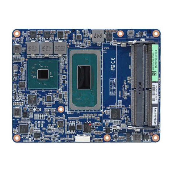
Page 15: Product Overview
ESM-TGH User’s Manual 2.1 Product Overview ESM-TGH User’s Manual 15... -
Page 16: Connector List
5 x 2 header, pitch 2.00mm BIOS_SPI1 CN1A COM Express connector 1 COM Express connector 2 CN1B SODIMM1 260-pin DDR4 SDRAM DIMM socket SODIMM2 260-pin DDR4 SDRAM DIMM socket SODIMM3 260-pin DDR4 SDRAM DIMM socket AT/ATX mode selector 16 ESM-TGH User’s Manual... -
Page 17: Setting Jumpers & Connectors
ATX mode *Default 2.3.1.1 Signal Description –AT/ATX mode selection AT/ATX mode Description AT mode Auto-power on, no need to press Power button to enable power on/off ATX mode Press the power button to enable power on/off ESM-TGH User’s Manual 17... -
Page 18: Com Express Connector 1 (Cn1A)
SER1_TX A101 B101 FAN_PWMOUT A100 B100 SER0_RX SER0_TX TYPE10# TPM_PP VGA_I2C_DAT VGA_I2C_CK VGA_VSYNC GPO0 VGA_HSYNC VGA_BLU +3.3V_SPI VGA_GRN PCIE_CLK_REF- VGA_RED PCIE_CLK_REF+ CB_EDP_HDP +ATX5VSB +ATX5VSB GPI3 +ATX5VSB LVDS_I2C_DAT/EDP_AUX- A84 +ATX5VSB LVDS_BKLT_CTRL/ LVDS_I2C_CK/EDP_AUX+ EDP_BKLT_CTRL LVDS_A_CK-/EDP_TX3- LVDS_B_CK- LVDS_A_CK+/EDP_TX3+ LVDS_B_CK+ 18 ESM-TGH User’s Manual... - Page 19 PCIE_RX2+ A60 B60 PCIE_TX3- A59 B59 PCIE_RX3- PCIE_TX3+ A58 B58 PCIE_RX3+ A57 B57 GPO2 PCIE_TX4- A56 B56 PCIE_RX4- PCIE_TX4+ A55 B55 PCIE_RX4+ GPI0 A54 B54 GPO1 PCIE_TX5- A53 B53 PCIE_RX5- PCIE_TX5+ A52 B52 PCIE_RX5+ A51 B51 ESM-TGH User’s Manual 19...
- Page 20 HDA_RST# A30 B30 HDA_SDIN0 HDA_SYNC A29 B29 HDA_SDIN1 (S)ATA_ACT# A28 B28 BATLOW# A27 B27 SATA2_RX- A26 B26 SATA3_RX- SATA2_RX+ A25 B25 SATA3_RX+ SUS_S5# A24 B24 PWR_OK SATA2_TX- A23 B23 SATA3_TX- SATA2_TX+ A22 B22 SATA3_TX+ A21 B21 20 ESM-TGH User’s Manual...
- Page 21 GBE0_MDI0- A12 B12 PWRBTN# A11 B11 LPC_CLK/ GBE0_MDI1+ A10 B10 ESPI_CK LPC_DRQ1#/ GBE0_MDI1- ESPI_ALERT1# LPC_DRQ0#/ GBE0_LINK# ESPI_ALERT0# LPC_AD3/ GBE0_MDI2+ ESPI_IO_3 LPC_AD2/ GBE0_MDI2- ESPI_IO_2 LPC_AD1/ GBE0_LINK2500# A5 ESPI_IO_1 LPC_AD0/ GBE0_LINK1000# A4 ESPI_IO_0 LPC_FRAME#/ GBE0_MDI3+ ESPI_CS0# GBE0_MDI3- GBE0_ACT# ESM-TGH User’s Manual 21...
-
Page 22: Signal Description - Com Express Connector 1 (Cn1A)
PCI Express Differential Receive Pair 0-5 2.3.2.1.4 Flat Panel LVDS Signals Signal Signal Description LVDS_BKLT_CTRL Controls panel digital power. LVDS_I2C_CK I2C clock output for LVDS display use. LVDS_I2C_DAT I2C data line for LVDS display use. LVDS_VDD_EN LVDS panel power enables. 22 ESM-TGH User’s Manual... -
Page 23: Lpc/Espi Signals
Signal Description SUS_S3# Indicates system is in Suspend to RAM state. Active low output. BATLOW# Indicates that external battery is low PWRBTN# Power button to bring system out of S5 (soft off), active on rising edge. ESM-TGH User’s Manual 23... -
Page 24: Sata Signals
General purpose I2C port data I/O line. 2.3.2.1.11 USB3.0 Signals Signal Signal Description USB_SSTX[0:1]+ Additional transmit signal differential pairs for the SuperSpeed USB data path. USB_SSTX[0:1]- USB_SSRX[0:1]+ Additional receive signal differential pairs for the SuperSpeed USB data path. USB_SSRX[0:1]- 24 ESM-TGH User’s Manual... -
Page 25: Com Express Connector 2 (Cn1B)
C103 D103 PEG_RX15- C102 D102 PEG_TX15- PEG_RX15+ C101 D101 PEG_TX15+ C100 D100 PEG_RX14- PEG_TX14- PEG_RX14+ PEG_TX14+ PEG_RX13- PEG_TX13- PEG_RX13+ PEG_TX13+ PEG_RX12- PEG_TX12- PEG_RX12+ PEG_TX12+ PEG_RX11- PEG_TX11- PEG_RX11+ PEG_TX11+ PEG_RX10- PEG_TX10- PEG_RX10+ PEG_TX10+ PEG_RX9- PEG_TX9- PEG_RX9+ PEG_TX9+ ESM-TGH User’s Manual 25... - Page 26 C60 D60 PEG_RX2- C59 D59 PEG_TX2- PEG_RX2+ C58 D58 PEG_TX2+ TYPE1# C57 D57 TYPE2# PEG_RX1- C56 D56 PEG_TX1- PEG_RX1+ C55 D55 PEG_TX1+ TYPE0# C54 D54 PEG_LAN_RV# PEG_RX0- C53 D53 PEG_TX0- PEG_RX0+ C52 D52 PEG_TX0+ C51 D51 26 ESM-TGH User’s Manual...
- Page 27 DDI2_CTRLCLK_AUX+ C32 D32 DDI1_PAIR2+ C31 D31 C30 D30 DDI1_PAIR1- C29 D29 DDI1_PAIR1+ C28 D28 RSVD7 C27 D27 DDI1_PAIR0- C26 D26 DDI1_PAIR0+ C25 D25 DDI1_HPD C24 D24 PCIE_RX7- C23 D23 PCIE_TX7- PCIE_RX7+ C22 D22 PCIE_TX7+ C21 D21 ESM-TGH User’s Manual 27...
- Page 28 C17 D17 C16 D16 DDI1_CTRLDATA_AUX- C15 D15 DDI1_CTRLCLK_AUX+ C14 D14 USB_SSRX3+ C13 D13 USB_SSTX3+ USB_SSRX3- C12 D12 USB_SSTX3- C11 D11 USB_SSRX2+ C10 D10 USB_SSTX2+ USB_SSRX2- USB_SSTX2- USB_SSRX1+ C7 USB_SSTX1+ USB_SSRX1- USB_SSTX1- USB_SSRX0+ C4 USB_SSTX0+ USB_SSRX0- USB_SSTX0- 28 ESM-TGH User’s Manual...
-
Page 29: Signal Description - Com Express Connector 2 (Cn1B)
PCI Express Differential Transmit Pair 6 PCIE_RX6 +/- PCI Express Differential Receive Pair 6 2.3.3.1.4 PEG PCI Express Lanes Signals Signal Signal Description PEG_TX[0:15]+ PCI Express Graphics transmit differential paris. PEG_TX[0:15]- PEG_RX[0:15]+ PCI Express Graphics recevie differential paris. PEG_RX[0:15]- ESM-TGH User’s Manual 29... -
Page 30: Installing Heatsink / Cooler
2.4 Installing Heatsink / Cooler Standard Temperature Heat spreader Cooler Step1. Using 5 screws (M2.5-16L) to lock the heat spreader and Cooler through PCB screw holes from top to bottom. Note: Screw Size/Q’TY - M2.5-16L Ni*5pcs 30 ESM-TGH User’s Manual... - Page 31 ESM-TGH User’s Manual Wide Temperature Heat spreader Cooler Step1. Using 5 screws (M2.5-16L) to lock the heat spreader and Cooler through PCB screw holes from top to bottom. Note: Screw Size/Q’TY - M2.5-16L Ni*5pcs ESM-TGH User’s Manual 31...
-
Page 32: Bios Setup
ESM-TGH User’s Manual 3. BIOS Setup 32 ESM-TGH User’s Manual... -
Page 33: Introduction
If the message disappears before you respond and you still wish to enter Setup, restart the system to try again by turning it OFF then ON or pressing the "RESET" button on the system case. You may also restart by simultaneously pressing <Ctrl>, <Alt>, and <Delete> keys. ESM-TGH User’s Manual 33... -
Page 34: Using Setup
Note: Some of the navigation keys differ from one screen to another. To Display a Sub Menu Use the arrow keys to move the cursor to the sub menu you want. Then press <Enter>. A “” pointer marks all sub menus. 34 ESM-TGH User’s Manual... -
Page 35: Getting Help
Even a seemingly small change to the chipset setup has the potential for causing you to use the override. ESM-TGH User’s Manual 35... -
Page 36: Bios Setup
<Enter> to accept and enter the sub-menu. 3.6.1 Main Menu This section allows you to record some basic hardware configurations in your computer and set the system clock. 36 ESM-TGH User’s Manual... -
Page 37: System Language
Note: The BIOS setup screens shown in this chapter are for reference purposes only, and may not exactly match what you see on your screen. Visit the Avalue website (www.avalue.com.tw) to download the latest product and BIOS information. ESM-TGH User’s Manual 37... -
Page 38: Advanced Menu
Use the CPU configuration menu to view detailed CPU specification and configure the CPU. Item Options Description Intel (VMX) Virtualization Disabled When enabled, a VMM can utilize the additional Technology Enabled[Default] hardware capabilities provided by Vanderpool 38 ESM-TGH User’s Manual... -
Page 39: Power & Performance
ESM-TGH User’s Manual Technology. All[Default] Number of cores to enable in each processor Active Processor Cores package. 3.6.2.2 Power & Performance 3.6.2.2.1 CPU – Power Management Control ESM-TGH User’s Manual 39... -
Page 40: Gt - Power Management Control
Check to enable render standby RC6(Render Standby) Disabled support. Default Max Frequency[Default],/ 100Mhz/150Mhz/200Mhz/250Mhz/ 300Mhz/350Mhz/400Mhz/450Mhz/ Maximum GT frequency 500Mhz/550Mhz/600Mhz/650Mhz/ Auto Updated. 700Mhz/750Mhz/800Mhz/850Mhz/ 900Mhz/950Mhz/1000Mhz/1050Mhz/ 1100Mhz/1150Mhz/1200Mhz Enable: Disables Turbo GT Enabled Disable Turbo GT frequency frequency. Disabled: GT Disabled[Default] frequency is not limited. 40 ESM-TGH User’s Manual... -
Page 41: Pch-Fw Configuration
ESM-TGH User’s Manual 3.6.2.3 PCH-FW Configuration 3.6.2.3.1 Firmware Update Configuration Item Option Description Disabled[Default], ME FW Image Re-Flash Enable/Disable Me FW Image Re-Flash function. Enabled ESM-TGH User’s Manual 41... -
Page 42: Ptt Configuration
3.6.2.3.2 PTT Configuration 3.6.2.4 Trusted Computing Item Options Description Enables or Disables BIOS support for security device. Disable, Security Device Support O.S. will not show Security Device. TCG EFI protocol Enable[Default] and INT1A interface will not be available. 42 ESM-TGH User’s Manual... -
Page 43: Apci Settings
S3 (Suspend to RAM)[Default] button is pressed. 3.6.2.6 IT5571 Super IO Configuration You can use this item to set up or change the IT5571 Super IO configuration for serial ports. Please refer to 3.6.2.6.1 ~ 3.6.2.6.2 for more information. ESM-TGH User’s Manual 43... -
Page 44: Serial Port 1 Configuration
Set Parameters of Serial Port 1 (COMA). Serial Port 2 Configuration Set Parameters of Serial Port 2 (COMB). 3.6.2.6.1 Serial Port 1 Configuration Item Option Description Enabled[Default], Serial Port Enable or Disable Serial Port (COM). Disabled 3.6.2.6.2 Serial Port 2 Configuration 44 ESM-TGH User’s Manual... -
Page 45: Hw Monitor
ESM-TGH User’s Manual Item Option Description Enabled[Default], Serial Port Enable or Disable Serial Port (COM). Disabled 3.6.2.7 HW Monitor Item Options Description Enabled, Smart Fan Function Enables or Disables Smart Fan. Disabled[Default] ESM-TGH User’s Manual 45... -
Page 46: Smart Fan Mode Configuration
Mode 05/Mode 06/ Mode 07/ Mode 08/ CPU Smart Fan Mode CPU Smart Fan Mode Select. Mode 09/Mode 10/ Mode 11/ Mode 12/ Mode 13/Mode 14/ Mode 15/ Mode 16/ Mode 17/Mode 18/ Mode 19/ Mode 20 Fan PWM(0-255) Fan PWM duty. 46 ESM-TGH User’s Manual... -
Page 47: S5 Rtc Wake Settings
Options Description Disabled, Enable or disable System wake on alarm event. Select Wake system from S5 Fixed Time[Default] Fixed Time, system will wake on the hr::min::sec Dynamic Time specified. Select Dynamic Time, System will wake on ESM-TGH User’s Manual 47... - Page 48 Select Fixed Time, system will wake on the Wake system from S5 Fixed Time hr::min::sec specified. Select Dynamic Time, System Dynamic Time[Default] will wake on the current time + Increase minute(s). Wake up minute increase 1-5. 48 ESM-TGH User’s Manual...
-
Page 49: Serial Port Console Redirection
ESM-TGH User’s Manual 3.6.2.9 Serial Port Console Redirection Item Options Description Disabled[Default], Console Redirection Console Redirection Enable or Disable. Enabled Disabled[Default], Console Redirection EMS Console Redirection Enable or Disable. Enabled 3.6.2.9.1 COM0 ESM-TGH User’s Manual 49... - Page 50 With this mode enabled only text will be sent. Recorder Mode Enabled This is to capture Terminal data. Disabled[Default] Enables or disables extended terminal Resolution 100x31 Enabled resolution. VT100[Default] Intel Linux XTERMR6 Putty KeyPad Select FunctionKey and KeyPad on Putty. ESCN VT400 50 ESM-TGH User’s Manual...
-
Page 51: Com1
Stop bits indicate the end of a serial data packet. (A start bit indicates the beginning). 1[Default] Stop Bits The standard setting is 1 stop bit. Communication with slow devices may require more than 1 stop bit. ESM-TGH User’s Manual 51... -
Page 52: Console Redirection Settings
VT-UTF8 is the preferred terminal type for out-of-band VT100+ management. The next best choice is VT100+ and Terminal Type VT-UTF8[Default], then VT100+ and them VT100. See above, in Console ANSI Redirection Settings page, for more Help with Terminal 52 ESM-TGH User’s Manual... -
Page 53: Acoustic Management Configuration
Flow Control Hardware RTS/CTS flow. Once the buffers are empty, a ‘start’ signal can be Software Xon/Xoff sent to re-start the flow. Hardware flow control uses two wires to send start/stop signals. 3.6.2.10 Acoustic Management Configuration ESM-TGH User’s Manual 53... -
Page 54: Usb Configuration
Mass storage device emulation type. ‘AUTO’ Auto[Default] Floppy enumerates devices according to their media Mass Storage Devices Forced FDD format. Optical drives are emulated as ‘CDROM’, drives with no media will be Hard Disk CD-ROM emulated according to a drive type. 54 ESM-TGH User’s Manual... -
Page 55: Network Stack Configuration
3.6.2.12 Network Stack Configuration Item Options Description Enabled Network Stack Enable/Disable UEFI Network Stack. Disabled[Default] Item Options Description Enabled[Default] Network Stack Enable/Disable UEFI Network Stack. Disabled Ipv4 PXE Support Enabled Enable Ipv4 PXE Boot Support. If disabled IPV4 ESM-TGH User’s Manual 55... -
Page 56: Nvme Configuration
HTTP boot option will not be created. Wait time to press ESC key to abort the PXE PXE boot wait time boot. Number of times presence of media will be Media detect count checked. 3.6.2.13 NVMe Configuration 56 ESM-TGH User’s Manual... -
Page 57: Tls Auth Configuration
ESM-TGH User’s Manual 3.6.2.14 Tls Auth Configuration 3.6.2.14.1 Console Redirection Settings Item Description Cert GUID Input digit character in 11111111-2222-3333-4444-1234567890ab format. ESM-TGH User’s Manual 57... -
Page 58: Chipset
ESM-TGH User’s Manual 3.6.3 Chipset 3.6.3.1 System Agent (SA) Configuration Item Option Description Enabled[Default] VT-d VT-d capability. Disabled 58 ESM-TGH User’s Manual... -
Page 59: Memory Configuration
Maximum Value of TOLUD. Dynamic /1 GB/1.25 GB/1.5 assignment would adjust TOLUD Max TOLUD GB/1.75 GB/2 GB/2.25 automatically based on largest MMIO GB/2.5 GB/2.75 GB/3 length of installed graphic controller. GB/3.25 GB/3.5 GB 3.6.3.1.2 Graphics Configuration ESM-TGH User’s Manual 59... -
Page 60: Pch-Io Configuration
Specify what state to go to when power is re-applied after State After G3 S5 State a power failure (G3 state). TRUE[Default] Enable/Disable setting SPD Write Disable. For security SPD Write Disable FALSE recommendations, SPD write disable bit must be set. 60 ESM-TGH User’s Manual... -
Page 61: Pci Express Configuration
3.6.3.2.1.1 PCIe Root Port 5 (PCIEX4_1.1) Item Option Description Enabled[Default], PCIe Root Port 5 (PCIEX4_1.1) Control the PCI Express Root Port. Disabled Set the ASPM Level: Force L0s – Force all Disabled[Default], ASPM links to L0s State AUTO – BIOS auto ESM-TGH User’s Manual 61... - Page 62 L0s State AUTO – BIOS auto ASPM configure DISABLE – Disables ASPM. L0sL1 Auto Disabled[Default] L1 Substates L1.1 PCI Express L1 Substates settings. L1.1 & L1.2 Auto[Default] Gen1 PCIe Speed Configure PCIe Speed. Gen2 Gen3 62 ESM-TGH User’s Manual...
- Page 63 L0s State AUTO – BIOS auto ASPM configure DISABLE – Disables ASPM. L0sL1 Auto Disabled[Default] L1 Substates L1.1 PCI Express L1 Substates settings. L1.1 & L1.2 Auto[Default] Gen1 PCIe Speed Configure PCIe Speed. Gen2 Gen3 ESM-TGH User’s Manual 63...
- Page 64 L0s State AUTO – BIOS auto ASPM configure DISABLE – Disables ASPM. L0sL1 Auto Disabled[Default] L1 Substates L1.1 PCI Express L1 Substates settings. L1.1 & L1.2 Auto[Default] Gen1 PCIe Speed Configure PCIe Speed. Gen2 Gen3 64 ESM-TGH User’s Manual...
- Page 65 L0s State AUTO – BIOS auto ASPM configure DISABLE – Disables ASPM. L0sL1 Auto Disabled[Default] L1 Substates L1.1 PCI Express L1 Substates settings. L1.1 & L1.2 Auto Gen1 PCIe Speed Configure PCIe Speed. Gen2 Gen3[Default] ESM-TGH User’s Manual 65...
- Page 66 L0s State AUTO – BIOS auto ASPM configure DISABLE – Disables ASPM. L0sL1 Auto Disabled[Default] L1 Substates L1.1 PCI Express L1 Substates settings. L1.1 & L1.2 Auto[Default] Gen1 PCIe Speed Configure PCIe Speed. Gen2 Gen3 66 ESM-TGH User’s Manual...
- Page 67 L0s State AUTO – BIOS auto ASPM configure DISABLE – Disables ASPM. L0sL1 Auto Disabled[Default] L1 Substates L1.1 PCI Express L1 Substates settings. L1.1 & L1.2 Auto[Default] Gen1 PCIe Speed Configure PCIe Speed. Gen2 Gen3 ESM-TGH User’s Manual 67...
- Page 68 L0s State AUTO – BIOS auto ASPM configure DISABLE – Disables ASPM. L0sL1 Auto Disabled[Default] L1 Substates L1.1 PCI Express L1 Substates settings. L1.1 & L1.2 Auto[Default] Gen1 PCIe Speed Configure PCIe Speed. Gen2 Gen3 68 ESM-TGH User’s Manual...
- Page 69 L0s State AUTO – BIOS auto ASPM configure DISABLE – Disables ASPM. L0sL1 Auto Disabled[Default] L1 Substates L1.1 PCI Express L1 Substates settings. L1.1 & L1.2 Auto[Default] Gen1 PCIe Speed Configure PCIe Speed. Gen2 Gen3 ESM-TGH User’s Manual 69...
- Page 70 Enabled = keep clock enabledeven if Disabled unused. Disabled = Disable clock. Platform-POR = CLKREQ signal is assigned Platform-POR ClkReq for Clock4 to CLKSRC according to board layout. Disabled[Default], Disabled = CLKREQ will not be used. 70 ESM-TGH User’s Manual...
-
Page 71: Sata And Rst Configuration
Options Description Enabled[Default] SATA Controller(s) Enable/Disable SATA Device. Disabled, AUTO[Default] Gen1 1.5 Gb/s SATA Speed Limitation Set the maximum speed of SATA. Gen2 3.0 Gb/s Gen3 6.0 Gb/s Enabled[Default] SATA1/2/3/4 Enable or Disable SATA Port. Disabled ESM-TGH User’s Manual 71... -
Page 72: Usb Configuration
ESM-TGH User’s Manual 3.6.3.2.3 USB Configuration Item Option Description Selectively Enable/Disable the corresponding USB Disabled[Default] USB Port Disable Override port from reporting a Device Connection to the Select Per-Pin controller. 72 ESM-TGH User’s Manual... -
Page 73: Hd Audio Configuration
Specifies DSP enabled system compliance: 1.Non-UAA (IntelSST driver support only – Audio DSP Non-UAA (IntelSST) CC_040100) 2. UAA (HD Audio Inbox or IntelSST driver support – CC_040380) Compliance Mode UAA (HDA Inbox/IntelSST)[Default] Note: NHLT (DMIC/BT/I2S configuration)is published for non-UAA only. ESM-TGH User’s Manual 73... -
Page 74: Board & Panel Configuration
Panel Brightness Control Method. 1.BIOS Panel Brightness Control BIOS[Default] 2.Brightness Button 3.Variable Resistor Method OS Driver 4.OS Driver. Panel Brightness Select Panel back light PWM duty. 100%[Default] Panel Back Light PWM 200[Default] Select Panel back light PWM Frequency. 74 ESM-TGH User’s Manual... - Page 75 CS2# range : 4Eh/4Fh. via CS3# via CS0#[Default] via CS1# Set CS# IO rounting for 2Eh Decode eSPI decode Port 2Eh/2Fh via CS2# range : 2Eh/2Fh. via CS3# Disabled[Default] SHOW DMI INFO SHOW DMI INFO. Enabled ESM-TGH User’s Manual 75...
-
Page 76: Security
ESM-TGH User’s Manual 3.6.4 Security Administrator Password Set setup Administrator Password User Password Set User Password 76 ESM-TGH User’s Manual... -
Page 77: Boot
Setup Prompt Timeout 1~ 65535 key. 65535(0xFFFF) means indefinite waiting. Bootup NumLock State Select the keyboard NumLock state Off[Default] Disabled Quiet Boot Enables or disables Quiet Boot option Enabled[Default] Boot Option #1 Set the system boot order. ESM-TGH User’s Manual 77... -
Page 78: Save And Exit
This option restores all BIOS settings to the factory default. This option is useful if the controller exhibits unpredictable behavior due to an incorrect or inappropriate BIOS setting. 3.6.6.4 Launch EFI Shell from filesystem device Attempts to Launch EFI Shell application (Shellx64.efi) from one of the available filesystem devices. 78 ESM-TGH User’s Manual... -
Page 79: Drivers Installation
ESM-TGH User’s Manual 4. Drivers Installation Note: Installation procedures and screen shots in this section are for your reference and may not be exactly the same as shown on your screen. ESM-TGH User’s Manual 79... -
Page 80: Install Chipset Driver
Windows 10 operation system. If the warning message appears while the installation process, click Continue to go on. Step 3. Click Install. Step 4. Complete setup. Step1. Click Next. Step 2. Click Accept. 80 ESM-TGH User’s Manual... -
Page 81: Install Dynamic Tuning Driver
If the warning message appears while the installation process, click Continue to go on. Step 3. Click Next to continue installation. Step 4. Click Finish to complete setup. Step1. Click Next to start installation. Step 2. Click Yes. ESM-TGH User’s Manual 81... -
Page 82: Install Vga Driver
Note: The installation procedures and screen shots in this section are based on Windows 10 operation system. Step 3. Click Start. Step 1. Click Begin installation. Step 4. Complete setup. Step 2. Click I agree. 82 ESM-TGH User’s Manual... -
Page 83: Install Ethernet Driver
Windows 10 operation system. Step 3. Click Next to continue setup. Step 1. Click Install Drivers and Step 4. Click Next. Software. Step 5. Click Install. Step 2. Click Next. ESM-TGH User’s Manual 83... - Page 84 ESM-TGH User’s Manual Step 6. Click Finish to complete the setup. 84 ESM-TGH User’s Manual...
-
Page 85: Install Me Driver
If the warning message appears while the installation process, click Continue to go on. Step 3. Click Next to continue installation. Step 4. Click Finish to complete setup. Step1. Click Next to start installation. Step 2. Click Next. ESM-TGH User’s Manual 85... -
Page 86: Install Serial Io Driver
If the warning message appears while the installation process, click Continue to go on. Step 3. Click Next. Step1. Click Next to start installation. Step 4. Click Next. Step 2. Click Next. Step 5. Click Finish to complete setup. 86 ESM-TGH User’s Manual... -
Page 87: Mechanical Drawing
ESM-TGH User’s Manual 5. Mechanical Drawing ESM-TGH User’s Manual 87... - Page 88 ESM-TGH User’s Manual Unit: mm 88 ESM-TGH User’s Manual...
Need help?
Do you have a question about the ESM-TGH and is the answer not in the manual?
Questions and answers