
Subscribe to Our Youtube Channel
Related Manuals for Avalue Technology EBM-QM87U


Summary of Contents for Avalue Technology EBM-QM87U
- Page 1 EBM-QM87U Intel® 4th Generation ULT Processor 5.25” Mini Module Quick Installation Guide Ed – 23 April 2014 Part No. E2017582200R...
-
Page 2: Fcc Statement
Disclaimer Avalue Technology Inc. reserves the right to make changes, without notice, to any product, including circuits and/or software described or contained in this manual in order to improve design and/or performance. Avalue Technology assumes no responsibility or liability for the... -
Page 3: Life Support Policy
Applications that are described in this manual are for illustration purposes only. Avalue Technology Inc. makes no representation or warranty that such application will be suitable for the specified use without further testing or modification. -
Page 4: Product Warranty
A product returned without proof of the purchase date is not eligible for warranty service. Write the RMA number visibly on the outside of the package and ship it prepaid to your dealer. 4 EBM-QM87U Quick Installation Guide... -
Page 5: Getting Started
1.2 Packing List Before you begin installing your single board, please make sure that the following materials have been shipped: 1 x EBM-QM87U Intel® 4th Generation ULT Processor 5.25” Mini Module 1 x DVD-ROM or CD-ROM contains the followings: ... - Page 6 EBM-QM87U Quick Installation Guide 2. Hardware Configuration 6 EBM-QM87U Quick Installation Guide...
-
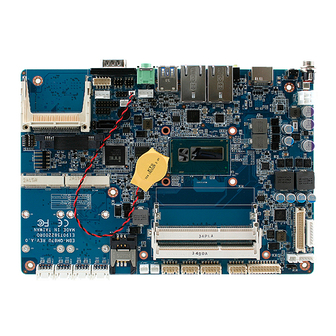
Page 7: Product Overview
Quick Installation Guide 2.1 Product Overview EBM-QM87U Quick Installation Guide 7... -
Page 8: Jumper And Connector List
3 x 1 header, pitch 2.00mm Multi-function select DIP switch 6pin Serial port 1/ 2 – RS485 mode select DIP switch 6pin Connectors Label Function Note Compact Flash card connector CFCARD COM1 Serial Port 1 connector D-sub 9 pin, male 8 EBM-QM87U Quick Installation Guide... - Page 9 4 x 2 header, pitch 2.00mm JSPI JEC_SPI EC_Program 4 x 2 header, pitch 2.00mm SPWR SATA Power connector 2 x 1 wafer, pitch 2.00mm SATA1 Serial ATA connector SIM card slot HDMI connector HDMI HP_OUT Audio line-out connector EBM-QM87U Quick Installation Guide 9...
-
Page 10: Setting Jumpers & Connectors
EBM-QM87U Quick Installation Guide 2.3 Setting Jumpers & Connectors 2.3.1 SATA Power select (JP1) * Default Signal SATA1 P7 2.3.2 Clear CMOS (JP4) Protect* Clear CMOS * Default 10 EBM-QM87U Quick Installation Guide... - Page 11 Auto Direction* RTS# Control 485TXP external OPEN* biasing resistor 485TXN external OPEN* biasing resistor In Serial Port 2 mode Auto Direction* RTS# Control 485TXP external * Default OPEN* biasing resistor 485TXN external OPEN* biasing resistor EBM-QM87U Quick Installation Guide 11...
- Page 12 EBM-QM87U Quick Installation Guide 2.3.5 Serial port 1/ 2 pin9 signal select (JRI1/ JRI2) Ring* +12V JRI2 JRI1 * Default 2.3.6 LCD backlight brightness adjustment (JVR) * Default Signal DC MODE VBRIGHT * Default PWM MODE 12 EBM-QM87U Quick Installation Guide...
- Page 13 For inverters with adjustable Backlight function, it is possible to control the LCD brightness through the VR signal controlled by JVR. Please see the JVR section for detailed circuitry information. 2.3.8 LCD Inverter connector (JBKL2) Signal +12V EBM-QM87U Quick Installation Guide 13...
- Page 14 EBM-QM87U Quick Installation Guide 2.3.9 CPU fan connector (CPU_FAN) Signal FAN_PWM0 EC_TACH0 +12V 2.3.10 System fan connector (SYS_FAN) Signal FAN_PWM1 EC_TACH1 +12V 14 EBM-QM87U Quick Installation Guide...
- Page 15 Quick Installation Guide 2.3.11 Serial port 2 connector (JCOM2) RS-232 Mode Signal Signal NRXDB# NDCDB NDTRB# NTXDB NDSRB# NCTSB# NRTSB# NRIB# RS-422 Mode Signal Signal 485TXP 485TXN 485RXN 485RXP RS-485 Mode Signal PIN PIN Signal 485TXP 485TXN EBM-QM87U Quick Installation Guide 15...
- Page 16 Serial port 3/ 4/ 5/ 6 connector (COM3/ COM4/ COM5/ COM6) Signal PIN PIN Signal JCOM6 COM_RI# JCOM5 COM_RTS# COM_CTS# JCOM4 COM_DSR# JCOM3 COM_TXD COM_DTR# COM_DCD# COM_RXD 2.3.13 LED indicator connector (JLED) Signal PIN PIN Signal PWR_LED# +5VSB HDD_LED# LAN1_ACT# +V3P3M LAN2_ACT# +V3P3A PWR_BTN 16 EBM-QM87U Quick Installation Guide...
- Page 17 Quick Installation Guide 2.3.14 General purpose I/O connector (JDIO) Signal PIN PIN Signal SMB_CLK_VCC 18 17 SMB_DATA_VCC 2.3.15 Touch panel connector (JTOUCH) Signal THX- THX+ THPROBE_R THY+ THY- EBM-QM87U Quick Installation Guide 17...
- Page 18 EBM-QM87U Quick Installation Guide 2.3.16 SATA Power connector (SPWR) Signal 2.3.17 Power connector (PWR1) Signal Signal +V_DCIN +V_DCIN 18 EBM-QM87U Quick Installation Guide...
- Page 19 Quick Installation Guide 2.3.18 LVDS connector (JLVDS) Signal PIN PIN Signal LVDS_DDC_CLK LVDS_DDC_DATA LVDS_DATA1_P LVDS_DATA0_P LVDS_DATA1_N LVDS_DATA0_N LVDS_DATA3_P LVDS_DATA2_P LVDS_DATA3_N LVDS_DATA2_N LVDS_DATA5_P LVDS_DATA4_P LVDS_DATA5_N LVDS_DATA4_N LVDS_DATA7_P LVDS_DATA6_P LVDS_DATA7_N LVDS_DATA6_N LVDS_CLK2_P LVDS_CLK1_P LVDS_ CLK2_N LVDS_ CLK1_N +12V +12V EBM-QM87U Quick Installation Guide 19...
- Page 20 EBM-QM87U Quick Installation Guide 2.3.19 USB connector 1 (JUSB1) Signal Signal +VCC_USB23 +VCC_USB23 USB_DN2 USB_DN3 USB_DP2 USB_DP3 2.3.20 USB connector 2 (JUSB2) Signal Signal +VCC_USB45 +VCC_USB45 USB_DN4 USB_DN5 USB_DP4 USB_DP5 20 EBM-QM87U Quick Installation Guide...
- Page 21 LINEOUT_R LINEOUT_L LINE1_RIN LINE1_LIN MIC_RIN MIC_LIN FRONT_JD LINE1_JD MIC1_JD 2.3.22.1 Signal Description – Audio connector (JAUDIO) Signal Signal Description LINE1_JD AUDIO IN (LINE_RIN/LIN)sense pin FRONT_JD AUDIO Out(ROUT/LOUT) sense pin MIC1_JD MIC IN (MIC_RIN/LIN) sense pin EBM-QM87U Quick Installation Guide 21...
- Page 22 EBM-QM87U Quick Installation Guide 2.3.23 AMPLIFIER_R (JAMP_R) Signal AMP_ROUT- AMP_ROUT+ 2.3.24 AMPLIFIER_L (AMP_L) Signal AMP_LOUT- AMP_LOUT+ 22 EBM-QM87U Quick Installation Guide...
- Page 23 Quick Installation Guide 2.3.25 LPC connector (JLPC) Signal PIN PIN Signal L80LLAT L80HLAT +5VSB SERIRQ CLK_PCI_JLPC LPC_AD3 LPC_LFRAME# LPC_AD2 PLTRST# LPC_AD1 +V3P3S LPC_AD0 2.3.26 SPI connector (JSPI) Signal PIN PIN Signal HOLD# SPI_SI SPI_SO SPI_CLK SPI_CS0# +V3P3A_SPI EBM-QM87U Quick Installation Guide 23...
- Page 24 EBM-QM87U Quick Installation Guide 2.3.27 EC_Program (JEC_SPI) Signal PIN PIN Signal EC_SMDAT_DEBUG 10 EC_SMCLK_DEBUG EC_HOLD# EC_FMOSI EC_FMISO EC_FSCK EC_FSCE# +VSPI_EC 24 EBM-QM87U Quick Installation Guide...
Need help?
Do you have a question about the EBM-QM87U and is the answer not in the manual?
Questions and answers