
Related Manuals for Avalue Technology EBM-BDW


Summary of Contents for Avalue Technology EBM-BDW
- Page 1 EBM-BDW 5th Gen Intel® Core™ SoC Processor i7/i5/i3 5.25” Mini Module User’s Manual Ed – 21 July 2015 Part No. E2047582400R...
- Page 2 Disclaimer Avalue Technology Inc. reserves the right to make changes, witho ut notice, to any product, including circuits and/or software described or contained in this manual in order to improve design and/or performance. Avalue Technology assumes no responsibility or liability for the...
- Page 3 Applications that are described in this manual are for illustration purposes only. Avalue Technology Inc. makes no representation or warranty that such application will be suitable for the specified use without further testing or modification.
- Page 4 A product returned without proof of the purchase date is not eligible for warranty service. Write the RMA number visibly on the outside of the package and ship it prepaid to your dealer. 4 EBM-BDW User’s Manual...
-
Page 5: Table Of Contents
LPC connector (JLPC) ...................... 28 2.3.20 LVDS connector (JLVDS) ....................29 2.3.21 USB connector 1 (JUSB1) ....................30 2.3.22 USB connector 2 (JUSB2) ....................30 2.3.23 AMPLIFIER_R (JAMP_R)....................31 2.3.24 AMPLIFIER_L (AMP_L) ....................31 2.3.25 SPI connector (JSPI)......................32 EBM-BDW User’s Manual... - Page 6 SATA Configuration ...................... 53 3.6.2.10 Thermal Configuration ....................54 3.6.2.10.1 Platform Thermal Configuration..................54 3.6.2.11 Network Stack Configuration..................55 3.6.2.12 CSM Configuration......................56 3.6.2.13 USB Configuration ......................57 3.6.3 Chipset ..........................57 3.6.3.1 System Agent (SA) Configuration ................... 58 6 EBM-BDW User’s Manual...
- Page 7 Install Chipset Driver ..................70 Install Ethernet Driver ..................71 Install IRST Driver .................... 73 Install ME Driver ....................75 Install VGA Driver .................... 76 Install Audio Driver (For Realtek ALC892) ............78 5. Mechanical Drawing ..................... 79 EBM-BDW User’s Manual...
-
Page 8: Getting Started
1.2 Packing List Before you begin installing your single board, please make sure that the following materials have been shipped: 1 x EBM-BDW 5th Generation intel Core Processor 5.25” Mini Module 1 x Driver/Utility DVD-ROM ... -
Page 9: Document Amendment History
User’s Manual 1.3 Document Amendment History Revision Date Comment July 2015 Avalue Initial Release EBM-BDW User’s Manual... -
Page 10: Manual Objectives
We strongly recommend that you study this manual carefully before attempting to set up EBM-BDW or change the standard configurations. Whilst all the necessary information is available in this manual we would recommend that unless you are confident, you contact your supplier for guidance. -
Page 11: System Specifications
1 x USB 2.0 for Touch controller 1 x USB through mPCIe port GPIO 16-bit General Purpose I/O for DI (8bit) and DO(8bit) IC: PCA9555 Touch Interface 1 x USB 2.0 (EETI ETP-CP-MER4485XRU support 5 wire) Display EBM-BDW User’s Manual 11... - Page 12 1 x dual deck LED(green color for power-on indication/ Yellow color for HDD active indication) Power 1 x Lockable DC Jack Audio 1 x Headphone Audio Jack 1 x COM1 Mechanical & Environmental Power +12 ~ +26V, ErP Requirement 12 EBM-BDW User’s Manual...
- Page 13 Safety CE FCC Class B Others 4 screw holes for fixing heatsink without covering RAM Certifications Certification Information FCC Class B Software Support OS Information Win8, Win7, Linux Note: Specifications are subject to change without notice. EBM-BDW User’s Manual 13...
-
Page 14: Architecture Overview-Block Diagram
EBM-BDW User’s Manual 1.6 Architecture Overview—Block Diagram The following block diagram shows the architecture and main components of EBM-BDW. 14 EBM-BDW User’s Manual... -
Page 15: Hardware Configuration
User’s Manual 2. Hardware Configuration EBM-BDW User’s Manual 15... -
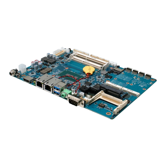
Page 16: Product Overview
EBM-BDW User’s Manual 2.1 Product Overview 16 EBM-BDW User’s Manual... -
Page 17: Jumper And Connector List
3 x 1 header, pitch 2.00mm (SATA1- Serial ATA connector) SATA 2 Pin 7 Power Mode selector 3 x 1 header, pitch 2.00mm Connectors Label Function Note CPU_FAN CPU fan connector 4 x 1 wafer, pitch 2.54mm EBM-BDW User’s Manual 17... - Page 18 4 x 2 header, pitch 2.00 mm SPWR SATA Power connector 2 x 1 wafer, pitch 2.00mm SATA1 Serial ATA connector 1 SIM card slot HDMI HDMI connector HP_OUT Audio line-out connector CFCARD Compact Flash card slot 18 EBM-BDW User’s Manual...
-
Page 19: Setting Jumpers & Connectors
Serial port 1/2 - RS-485 mode selector (SW2) In Serial Port 1 mode Auto Direction RTS# Control External biasing OPEN resistor External biasing OPEN resistor In Serial Port 2 mode Auto Direction RTS# Control External biasing OPEN resistor External biasing OPEN resistor EBM-BDW User’s Manual 19... -
Page 20: Serial Port 1/ 2 - Rs-422 Mode Selector (Sw3)
External biasing OPEN resistor External biasing OPEN resistor In Serial Port 2 mode External biasing OPEN resistor External biasing OPEN resistor 2.3.4 Serial port 1/ 2 pin9 signal select (JRI1/ JRI2) Ring* +12V JRI1 JRI2 * Default 20 EBM-BDW User’s Manual... -
Page 21: Sata Power Select (Jp1)
User’s Manual 2.3.5 SATA Power select (JP1) * Default Signal SATA_PWR1 SATA1_P7 * Default 2.3.6 Clear CMOS (JP4) Protect* Clear CMOS * Default EBM-BDW User’s Manual 21... -
Page 22: Lcd Backlight Brightness Adjustment (Jvr)
EBM-BDW User’s Manual 2.3.7 LCD backlight brightness adjustment (JVR) PWM Mode* DC Mode * Default 2.3.8 LED indicator connector (JLED) Signal PIN PIN Signal PWR_LED_FP# +5VSB HDD_LED# LAN1_ACT# +V3P3M LAN2_ACT# +V3P3A PWR_BTN_IN_EC# 22 EBM-BDW User’s Manual... -
Page 23: Lcd Inverter Connector 1 (Jbkl1)
For inverters with adjustable Backlight function, it is possible to control the LCD brightness through the VR signal controlled by JVR. Please see the JVR section for detailed circuitry information. 2.3.10 LCD Inverter connector 2 (JBKL2) Signal +12V EBM-BDW User’s Manual 23... -
Page 24: Cpu Fan Connector (Cpu_Fan)
EBM-BDW User’s Manual 2.3.11 CPU fan connector (CPU_FAN) Signal FAN_PWM0 EC_TACH0 +12V 2.3.12 System fan connector (SYS_FAN) Signal FAN_PWM1 EC_TACH1 +12V 24 EBM-BDW User’s Manual... -
Page 25: Serial Port 2 Connector (Jcom2)
User’s Manual 2.3.13 Serial port 2 connector (JCOM2) RS-232 Mode Signal Signal NRXDB# NDCDB NDTRB# NTXDB NDSRB# NCTSB# NRTSB# NRIB# RS-422 Mode Signal Signal 485TXP 485TXN 485RXN 485RXP RS-485 Mode Signal PIN PIN Signal 485TXP 485TXN EBM-BDW User’s Manual 25... -
Page 26: Serial Port 3/4/5/6 Connector (Jcom3/Jcom4/Jcom5/Jcom6)
2.3.14 Serial port 3/4/5/6 connector (JCOM3/JCOM4/JCOM5/JCOM6) Signal PIN PIN Signal COM_RI# JCOM6 COM_RTS# COM_CTS# JCOM5 COM_DSR# JCOM4 COM_TXD COM_DTR# JCOM3 COM_DCD# COM_RXD# 2.3.15 General purpose I/O connector (JDIO) Signal PIN PIN Signal I2C-SMB_CLK_VCC 18 17 I2C-SMB_DATA_VCC 26 EBM-BDW User’s Manual... -
Page 27: Touch Panel Connector (Jtouch)
User’s Manual 2.3.16 Touch panel connector (JTOUCH) Signal THX- THX+ THPROBE_R THY+ THY- 2.3.17 SATA Power connector (SPWR) Signal EBM-BDW User’s Manual 27... -
Page 28: Power Connector (Pwr1)
EBM-BDW User’s Manual 2.3.18 Power connector (PWR1) Signal Signal +V_DCIN +V_DCIN 2.3.19 LPC connector (JLPC) Signal PIN PIN Signal +5VSB SERIRQ CLK_PCI_JLPC LPC_AD3 LPC_LFRAME# LPC_AD2 PLTRST# LPC_AD1 LPC_AD0 28 EBM-BDW User’s Manual... -
Page 29: Lvds Connector (Jlvds)
User’s Manual 2.3.20 LVDS connector (JLVDS) Signal PIN PIN Signal LVDS_DDC_CLK LVDS_DDC_DATA LVDS_DATA1_P LVDS_DATA0_P LVDS_DATA1_N LVDS_DATA0_N LVDS_DATA3_P LVDS_DATA2_P LVDS_DATA3_N LVDS_DATA2_N LVDS_DATA5_P LVDS_DATA4_P LVDS_DATA5_N LVDS_DATA4_N LVDS_DATA7_P LVDS_DATA6_P LVDS_DATA7_N LVDS_DATA6_N LVDS_CLK2_P LVDS_CLK1_P LVDS_ CLK2_N LVDS_ CLK1_N +12V +12V EBM-BDW User’s Manual 29... -
Page 30: Usb Connector 1 (Jusb1)
EBM-BDW User’s Manual 2.3.21 USB connector 1 (JUSB1) Signal PIN PIN Signal +VCC_USB23 +VCC_USB23 USB_DN2 USB_DN3 USB_DP2 USB_DP3 2.3.22 USB connector 2 (JUSB2) Signal PIN PIN Signal +VCC_USB45 +VCC_USB45 USB_DN4 USB_DN5 USB_DP4 USB_DP5 30 EBM-BDW User’s Manual... -
Page 31: Amplifier_R (Jamp_R)
User’s Manual 2.3.23 AMPLIFIER_R (JAMP_R) Signal AMP_ROUT- AMP_ROUT+ 2.3.24 AMPLIFIER_L (AMP_L) Signal AMP_LOUT- AMP_LOUT+ EBM-BDW User’s Manual 31... -
Page 32: Spi Connector (Jspi)
Signal LINEOUT_R LINEOUT_L LINE1_RIN LINE1_LIN MIC_RIN MIC_LIN FRONT_JD LINE1_JD MIC1_JD 2.3.26.1 Signal Description – Audio connector (JAUDIO) Signal Signal Description LINE1_JD AUDIO IN (LINE_RIN/LIN)sense pin FRONT_JD AUDIO Out(ROUT/LOUT) sense pin MIC1_JD MIC IN (MIC_RIN/LIN) sense pin 32 EBM-BDW User’s Manual... -
Page 33: Ec_Program (Jec_Spi)
User’s Manual 2.3.27 EC_Program (JEC_SPI) Signal PIN PIN Signal EC_SMDAT EC_SMCLK EC_SMDAT_DEBUG EC_SMCLK_DEBUG EC_HOLD# EC_FMOSI EC_FMISO EC_FSCK EC_FSCE# +VSPI_EC 2.3.28 Battery connector (BT) Signal +VBAT EBM-BDW User’s Manual 33... -
Page 34: Osd For Front Panel Key (Jkey)
EBM-BDW User’s Manual 2.3.29 OSD for front panel key (JKEY) Signal +V3P3EC EC_PWM EC_GPIOJ1 EC_GPIOJ2 EC_GPIOJ3 EC_GPIOJ4 EC_DC 34 EBM-BDW User’s Manual... -
Page 35: Bios Setup
User’s Manual 3.BIOS Setup EBM-BDW User’s Manual 35... -
Page 36: Introduction
If the message disappears before you respond and you still wish to enter Setup, restart the system to try again by turning it OFF then ON or pressing the "RESET" button on the system case or restart by simultaneously pressing <Ctrl>, <Alt>, and <Delete> keys. 36 EBM-BDW User’s Manual... -
Page 37: Using Setup
Note: Some of the navigation keys differ from one screen to another. To Display a Sub Menu Use the arrow keys to move the cursor to the sub menu you want. Then press <Enter>. A “” pointer marks all sub menus. EBM-BDW User’s Manual 37... -
Page 38: Getting Help
BIOS Vendor and your systems manufacturer to provide the absolute maximum performance and reliability. Even a seemingly small change to the chipset setup has the potential for causing you to use the override. 38 EBM-BDW User’s Manual... -
Page 39: Bios Setup
Use the arrow keys to select among the items and press <Enter> to accept and enter the sub-menu. 3.6.1 Main Menu This section allows you to record some basic hardware configurations in your computer and set the system clock. EBM-BDW User’s Manual 39... -
Page 40: System Language
Visit the Avalue website (www.avalue.com.tw) to download the latest product and BIOS information. 3.6.2 Advanced Menu This section allows you to configure your CPU and other system devices for basic operation through the following sub-menus. 40 EBM-BDW User’s Manual... -
Page 41: Cpu Configuration
3.6.2.1 CPU Configuration Use the CPU configuration menu to view detailed CPU specification and configure the CPU. Item Options Description All[Default], Number of cores to enable in each processor Active Processor Cores package. 3.6.2.2 Trusted Computing EBM-BDW User’s Manual 41... -
Page 42: Apci Settings
Suspend Disabled APCI Sleep State system will enter when the S3 (Suspend to RAM)[Default] SUSPEND button is pressed. Disabled[Default] Enable or Disable S3 Video S3 Video Repost Enabled Repost. Disabled[Default] ErP Function ErP Function (Deep S5). Enabled 42 EBM-BDW User’s Manual... -
Page 43: Pch-Fw Configuration
Disabled delivery in S3(Sleep), USB Power state in S3-S5 Enabled[Default] S4(Hibernate), S5(Shut down) Modes. 3.6.2.4 PCH-FW Configuration Item Options Description ME Unconfig on RTC Clear Disabled Enable/Disable ME firmware un-configuration State On RTC Clear State. Enabled[Default] EBM-BDW User’s Manual 43... -
Page 44: Firmware Update Configuration
Me FW Image Re-Flash Enable/Disable Me FW Image Re-Flash function. Enabled 3.6.2.5 AMT Configuration Item Options Description Enable/Disable Intel® Active Management Disabled Intel AMT Technology BIOS Extension. Note: iAMT H/W Enabled[Default], is always enabled. This option just controls the 44 EBM-BDW User’s Manual... -
Page 45: Super Io Configuration
Set Parameters of Serial Port 3 (COMC). Serial Port 4 Configuration Set Parameters of Serial Port 4 (COMD). Serial Port 5 Configuration Set Parameters of Serial Port 3 (COME). Serial Port 6 Configuration Set Parameters of Serial Port 4 (COMF). EBM-BDW User’s Manual 45... -
Page 46: Serial Port 1 Configuration
IO=3E8h; IRQ=3,4,5,6,7,9,10,11,12; IO=2E8h; IRQ=3,4,5,6,7,9,10,11,12; RS232[Default], UART 232 422 485 RS485 Change the Serial Port mode. RS422 Enabled[Default], Enable or Disable 250kbps slew UART SLEW Disabled limiting. Enabled Enable or Disable RS-485/422 UART THRM Disabled[Default], receiver termination. 46 EBM-BDW User’s Manual... -
Page 47: Serial Port 2 Configuration
IO=3E8h; IRQ=3,4,5,6,7,9,10,11,12; IO=2E8h; IRQ=3,4,5,6,7,9,10,11,12; RS232[Default], UART 232 422 485 RS485 Change the Serial Port mode. RS422 Enabled[Default], Enable or Disable 250kbps slew UART SLEW Disabled limiting. Enabled Enable or Disable RS-485/422 UART THRM Disabled[Default], receiver termination. EBM-BDW User’s Manual 47... -
Page 48: Serial Port 3 Configuration
Description Enabled[Default], Enable or Disable Serial Port Serial Port Disabled (COM). Auto[Default] IO=3E8h; IRQ=10; IO=3F8h; IRQ=3,4,5,6,7,9,10,11,12; IO=2F8h; IRQ=3,4,5,6,7,9,10,11,12; Select an optimal setting for Change Settings IO=3E8h; IRQ=3,4,5,6,7,9,10,11,12; Super IO Device. IO=2E8h; IRQ=3,4,5,6,7,9,10,11,12; IO=200h; IRQ=3,4,5,6,7,9,10,11,12; IO=208h; IRQ=3,4,5,6,7,9,10,11,12; 48 EBM-BDW User’s Manual... -
Page 49: Serial Port 4 Configuration
Description Enabled[Default], Enable or Disable Serial Port Serial Port Disabled (COM). Auto[Default] IO=2E8h; IRQ=11; IO=3F8h; IRQ=3,4,5,6,7,9,10,11,12; IO=2F8h; IRQ=3,4,5,6,7,9,10,11,12; Select an optimal setting for Change Settings IO=3E8h; IRQ=3,4,5,6,7,9,10,11,12; Super IO Device. IO=2E8h; IRQ=3,4,5,6,7,9,10,11,12; IO=200h; IRQ=3,4,5,6,7,9,10,11,12; IO=208h; IRQ=3,4,5,6,7,9,10,11,12; EBM-BDW User’s Manual 49... -
Page 50: Serial Port 5 Configuration
Description Enabled[Default], Enable or Disable Serial Port Serial Port Disabled (COM). Auto[Default] IO=200h; IRQ=10; IO=3F8h; IRQ=3,4,5,6,7,9,10,11,12; IO=2F8h; IRQ=3,4,5,6,7,9,10,11,12; Select an optimal setting for Change Settings IO=3E8h; IRQ=3,4,5,6,7,9,10,11,12; Super IO Device. IO=2E8h; IRQ=3,4,5,6,7,9,10,11,12; IO=200h; IRQ=3,4,5,6,7,9,10,11,12; IO=208h; IRQ=3,4,5,6,7,9,10,11,12; 50 EBM-BDW User’s Manual... -
Page 51: Serial Port 6 Configuration
Description Enabled[Default], Enable or Disable Serial Port Serial Port Disabled (COM). Auto[Default] IO=208h; IRQ=11; IO=3F8h; IRQ=3,4,5,6,7,9,10,11,12; IO=2F8h; IRQ=3,4,5,6,7,9,10,11,12; Select an optimal setting for Change Settings IO=3E8h; IRQ=3,4,5,6,7,9,10,11,12; Super IO Device. IO=2E8h; IRQ=3,4,5,6,7,9,10,11,12; IO=200h; IRQ=3,4,5,6,7,9,10,11,12; IO=208h; IRQ=3,4,5,6,7,9,10,11,12; EBM-BDW User’s Manual 51... -
Page 52: H/W Monitor
EBM-BDW User’s Manual 3.6.2.7 H/W Monitor Item Options Description Disabled[Default] Smart Fan Function Enable or Disable Smart Fan. Enabled, 3.6.2.8 S5 RTC Wake Settings 52 EBM-BDW User’s Manual... -
Page 53: Sata Configuration
Gen2 Gen3 Disabled Port 0/1/2 Enable or Disable SATA Port. Enabled[Default] Hard Disk Drive[Default] Identify the SATA port is connected to Solid SATA Device Type State Drive or Hard Disk Drive. Solid State Drive EBM-BDW User’s Manual 53... -
Page 54: Thermal Configuration
ACPI Critical Trip Point – the point in which the Critical Trip Point OS will shut the system off. NOTE:100C is the Plan Of Record (POR) for all Intel mobile 100C processors. 110C Passive Trip Point This value controls the temperature of the Disabled, 54 EBM-BDW User’s Manual... -
Page 55: Network Stack Configuration
OS will read 10[Default], the temperature when passive cooling is enabled. Range 2 – 32. 3.6.2.11 Network Stack Configuration Item Options Description Disabled[Default] Network Stack Enable/Disable UEFI Network Stack. Enabled EBM-BDW User’s Manual 55... -
Page 56: Csm Configuration
Legacy[Default] Do not launch Controls the execution of UEFI and Legacy Video UEFI Video OpROM. Legacy[Default] Do not launch Determines OpROM execution policy for Other PCI devices UEFI[Default] devices other than Network, Storage, or Legacy Video. 56 EBM-BDW User’s Manual... -
Page 57: Usb Configuration
Floppy enumerates devices according to their media Hp v220w 1100 Forced FDD format. Optical drives are emulated as ‘CDROM’, drives with no media will be Hard Disk CD-ROM emulated according to a drive type. 3.6.3 Chipset EBM-BDW User’s Manual 57... -
Page 58: System Agent (Sa) Configuration
System Agent (SA) Configuration Item Option Description Disabled Check to enable VT-d function on VT-d Enabled[Default] MCH. 3.6.3.1.1 Graphics Configuration Item Option Description 128MB Select the Aperture Size. Note: Aperture Size 256MB[Default] Above 4GB MMIO BIOS assignment 58 EBM-BDW User’s Manual... -
Page 59: Lcd Control
Primary IGFX Boot Display HDMI display selection will appear based on your LVDS selection. VGA modes will be supported only on primary display. 1024x768 24/1[Default] Port1-EDP to LVDS (Chrotel 7511) Panel CH7511 EDID Panel Option 800x600 18/1 EDID Option. EBM-BDW User’s Manual 59... - Page 60 Select LVDS back light PWM Frequency. Frequency 1kHz 2kHz 3kHz 5kHz Select the Active LFP Configuration. No No LVDS LVDS: VBIOS does not enable LVDS. eDP Active LFP eDP Port-A[Default] Port-A:LFP Driven by Int-DisplayPort encoder from Port-A. (through PCH). 60 EBM-BDW User’s Manual...
-
Page 61: Memory Configuration
User’s Manual 3.6.3.1.2 Memory Configuration 3.6.3.2 PCH-IO Configuration Item Option Description Disabled PCH LAN(PHY) Controller Enable or disable LAN1 NIC. Enabled[Default] EBM-BDW User’s Manual 61... -
Page 62: Pci Express Configuration
The control of Active State Power Disabled DMI Link ASPM Control Management on both NB side and SB side Enabled[Default] of the DMI Link. Disabled[Default] Enable or disable PCI Express Subtractive Subtractive Decode Enabled Decode. 3.6.3.2.2 USB Configuration 62 EBM-BDW User’s Manual... -
Page 63: Pch Azalia Configuration
Disabled = Azalia will be unconditionally Azalia Enabled[Default] disabled Enabled = Azalia will be Auto unconditionally Enabled Auto = Azalia will be enabled if present, disabled otherwise. 15.3 dB[Default], 21.1 dB Amplifier Gain Select Amplifier Gain (dB). 27.2 dB 31.8 dB EBM-BDW User’s Manual 63... -
Page 64: Security
EBM-BDW User’s Manual 3.6.4 Security Administrator Password Set setup Administrator Password User Password Set User Password 3.6.4.1 Secure Boot menu 64 EBM-BDW User’s Manual... -
Page 65: Key Management
Image Execution Custom[Default] policy and manage Secure Boot Keys. 3.6.4.1.1 Key Management Item Option Description Enabled, Install Factory default Secure Boot Keys Default Key Provision Disabled[Default] when System is in Setup Mode. EBM-BDW User’s Manual 65... -
Page 66: Boot
Enables or disables boot with Disabled[Default] initialization of a minimal set of devices Fast Boot Enabled required to launch active boot option. Has no effect for BBS boot options. Boot Option #1/2 Sets the system boot order. 66 EBM-BDW User’s Manual... -
Page 67: Save And Exit
3.6.6 Save and exit 3.6.6.1 Save Changes and Reset Reset the system after saving the changes. 3.6.6.2 Discard Changes and Reset Any changes made to BIOS settings during this session of the BIOS setup program are EBM-BDW User’s Manual 67... -
Page 68: Restore Defaults
This option restores all BIOS settings to the factory default. This option is useful if the controller exhibits unpredictable behavior due to an incorrect or inappropriate BIOS setting. 3.6.6.4 Launch EFI Shell from filesystem device Attempts to Launch EFI Shell application (Shellx64.efi) from one of the available filesystem devices. 68 EBM-BDW User’s Manual... -
Page 69: Drivers Installation
User’s Manual 4. Drivers Installation Note: Installation procedures and screen shots in this section are for your reference and may not be exactly t he same as shown on your screen. EBM-BDW User’s Manual 69... -
Page 70: Install Chipset Driver
If the warning message Step 3. Wait while installing. appears while the installation process, click Continue to go on. Step1. Click Next. Step 4. Click Restart Now or Restart Later to complete setup. Step 2. Click Accept. 70 EBM-BDW User’s Manual... -
Page 71: Install Ethernet Driver
Continue to go on. Step 3. Click Next. Step1. Click Next to start installation. Step 4. Click Install. Step 2. Click Next to proceed setup. Step 5. Wait while installing. EBM-BDW User’s Manual 71... - Page 72 EBM-BDW User’s Manual Step 6. Wait while installing. Step 7. Click Finish to complete setup. 72 EBM-BDW User’s Manual...
-
Page 73: Install Irst Driver
If the warning message appears while the installation Step 3. Click Next. process, click Continue to go on. Step1. Click Next to start installation. Step 4. Click Next. Step 2. Click Next to proceed setup. Step 5. Click Next. EBM-BDW User’s Manual 73... - Page 74 EBM-BDW User’s Manual Step 6. Wait while installing. Step 7. Click Finish to complete setup. 74 EBM-BDW User’s Manual...
-
Page 75: Install Me Driver
Step 3. Click Next. process, click Continue to go on. Step1. Click Next to start installation. Step 4. Wait while installing. Step 2. Click Next to proceed setup. Step 5. Click Finish to complete setup. EBM-BDW User’s Manual 75... -
Page 76: Install Vga Driver
Windows 8.1 operation system. Step 3. Click Next. Step 1. Click Next to continue installation. Step 4. Click Next. Step 2. Step 5. Click Next. Click Yes to accept license agreement. 76 EBM-BDW User’s Manual... - Page 77 User’s Manual Step 6. Click Finish to complete setup. EBM-BDW User’s Manual 77...
-
Page 78: Install Audio Driver (For Realtek Alc892)
Windows 8 operation system. Step 3. Click Next to continue setup. Step 4. Wait while installing. Step 1. Click Next to continue setup. Step 5. Click Finish to complete the setup. Step 2. Click Next. 78 EBM-BDW User’s Manual... -
Page 79: Mechanical Drawing
User’s Manual 5. Mechanical Drawing EBM-BDW User’s Manual 79... - Page 80 EBM-BDW User’s Manual Unit: mm 80 EBM-BDW User’s Manual...
- Page 81 User’s Manual Unit: mm EBM-BDW User’s Manual 81...
Need help?
Do you have a question about the EBM-BDW and is the answer not in the manual?
Questions and answers