
Subscribe to Our Youtube Channel
Related Manuals for Avalue Technology EBM-A50M


Summary of Contents for Avalue Technology EBM-A50M
- Page 1 EBM-A50M 5.25" AMD eOntario Mini Module with AMD A50M Chipset + T40E Processor User’s Manual Ed – 10 November 2011 Copyright Notice Copyright 2011 Avalue Technology Inc., ALL RIGHTS RESERVED. Part No. E2047581700R...
- Page 2 Disclaimer Avalue Technology Inc. reserves the right to make changes, without notice, to any product, including circuits and/or software described or contained in this manual in order to improve design and/or performance. Avalue Technology assumes no responsibility or liability for the...
- Page 3 User’s Manual Life Support Policy Avalue Technology‟s PRODUCTS ARE NOT FOR USE AS CRITICAL COMPONENTS IN LIFE SUPPORT DEVICES OR SYSTEMS WITHOUT THE PRIOR WRITTEN APPROVAL OF Avalue Technology Inc. As used herein: 1. Life support devices or systems are devices or systems which, (a) are intended for...
- Page 4 Avalue Technology Inc. Room 805, Building 9,No.99 Tianzhou Rd., 2F keduka-Bldg, 2-27-3 Taito, Caohejing Development Area, Taito-Ku, Tokyo 110-0016 Japan Xuhui District, Shanghai Tel: +81-3-5807-2321 Tel: +86-21-5169-3609 Fax:+86-21-5445-3266 Fax: +81-3-5807-2322 Information: sales.china@avalue.com.cn Information: sales.japan@avalue.com.tw Service: service@avalue.com.tw Service: service@avalue.com.tw 4 EBM-A50M User‟s Manual...
- Page 5 (such as your sales receipt) in a shippable container. A product returned without proof of the purchase date is not eligible for warranty service. 5. Write the RMA number visibly on the outside of the package and ship it prepaid to your dealer. EBM-A50M User‟s Manual...
-
Page 6: Table Of Contents
Serial port 3/ 4/ 5/ 6 connector (JCOM3/ JCOM4/ JCOM5/ JCOM6) ........34 2.4.20 General purpose I/O connector (JDIO) ..................34 2.4.21 LVDS connector (JLVDS1) ......................35 Signal Description – LVDS Connecter (JLVDS) ................. 35 2.3.21.1 6 EBM-A50M User‟s Manual... - Page 7 3.6.2.8.2 Serial Port 1 Configuration ........................58 3.6.2.8.3 Parallel port Configuration ........................59 3.6.2.9 H/W Monitor ............................60 3.6.2.9.1 Smart Fan Mode configuration ......................60 3.6.3 Advanced Chipset Features ......................61 3.6.3.1 North Bridge ............................62 3.6.3.1.1 GFX Configuration.......................... 62 EBM-A50M User‟s Manual...
- Page 8 Restore Defaults ........................... 72 4. Drivers Installation....................... 73 Install Audio Driver (For Realtek ALC892) .............. 74 Install Display Driver (For AMD Fusion Accelerated Processors) ......75 Install Ethernet Driver (For Realtek 8111E) ............76 5. Mechanical Drawing ....................77 8 EBM-A50M User‟s Manual...
-
Page 9: Getting Started
1.2 Packing List Before you begin installing your single board, please make sure that the following materials have been shipped: 1 x EBM-A50M 1 x DVD-ROM or CD-ROM containing the followings: ... -
Page 10: Document Amendment History
EBM-A50M User’s Manual 1.3 Document Amendment History Revision Date Comment November Initial Release 2011 10 EBM-A50M User‟s Manual... -
Page 11: Manual Objectives
We strongly recommend that you study this manual carefully before attempting to interface with EBM-A50M series or change the standard configurations. Whilst all the necessary information is available in this manual we would recommend that unless you are confident, you contact your supplier for guidance. -
Page 12: System Specifications
HDMI: 1920 x 1200 @ 60 Hz Resolution Display port T56N :2560 x 1600 @ 60 Hz T40E:1920 x 1200 @ 60 Hz 18-bit LVDS : 1400 x 1050 @ 60 Hz Dual 24-bit LVDS : 1920 x 1200 @ 60 Hz 12 EBM-A50M User‟s Manual... - Page 13 Operating Temp. 0 to 60C (32~140 ℉) Storage Temp. -40~75°C (-40~167 ℉) Operating 0%~90% relative humidity, non-condensing Humidity Size (L x W) 8" x 5.75"x 0.75" (203 mm x 146 mm x 19mm) Weight 0.55lb (0.25kg) EBM-A50M User‟s Manual 13...
-
Page 14: Architecture Overview - Block Diagram
EBM-A50M User’s Manual 1.6 Architecture Overview – Block Diagram The following block diagram shows the architecture and main components of EBM-A50M. 14 EBM-A50M User‟s Manual... -
Page 15: Hardware Configuration
User’s Manual 2. Hardware Configuration EBM-A50M User‟s Manual 15... -
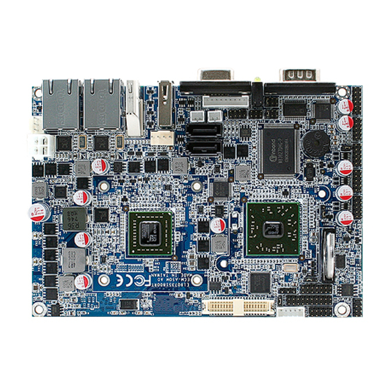
Page 16: Product Overview
EBM-A50M User’s Manual 2.1 Product Overview 16 EBM-A50M User‟s Manual... -
Page 17: Installation Procedure
Note: Make sure the heat sink and the CPU top surface are in total contact to avoid CPU overheating problem that would cause the system to hang or unstable EBM-A50M User‟s Manual 17... -
Page 18: Main Memory
EBM-A50M User’s Manual 2.2.1 Main Memory EBM-A50M provides Onboard 2G DDR3 1333 SDRAM, and One 204-pin DDR3 SODIMM socket supports up to 4GB DDR3 1333 SDRAM SODIMM Make sure to unplug the power supply before adding or removing SODIMMs or other system components. Failure to do so may cause severe damage to both the board and the components. - Page 19 (2) Static electricity can damage the electronic components of the computer or optional boards. Before proceeding, ensure that you are discharged of static electricity by briefly touching a grounded metal object. EBM-A50M User‟s Manual 19...
-
Page 20: Jumper And Connector List
Serial port 2 pin9 signal selector 3 x 2 header, pitch 2.0mm LCD backlight brightness adjustment 3 x 2 header, pitch 2.0mm DIP switch 6pin Multi-function select Serial port 1/ 2 – RS232/ 422/ 485 mode DIP switch 6pin selector 20 EBM-A50M User‟s Manual... - Page 21 LED indicator connector Mini-PCI connector 1 MPCIE1 Mini-PCI connector 2 (supports Optional MPCIE2 SIM CARD) PRINT Optional LPT Connector Power connector PWR1 PWR2 Power connector (colay PWR3) 2 x 2 wafer, pitch 2.0mm Reset button RSBTN EBM-A50M User‟s Manual 21...
- Page 22 2 x 1 wafer, pitch 2.0mm Serial ATA connector 1 SATA1 SATA2 Serial ATA connector 2 SATA3 SATA-HDD connector (Optional) USB1 USB connector 0&1 12V_PWR 12V Power Output (Max:1A) (Optional) 3 x 1 wafer, pitch 2.0mm 22 EBM-A50M User‟s Manual...
-
Page 23: Setting Jumpers & Connectors
2.4 Setting Jumpers & Connectors 2.4.1 Clear CMOS (JBAT) Protect* Clear CMOS * Default 2.4.2 Multi-function selector (SW1) AT SEL ATX SEL CF Master CF Slave Touch off Touch on Touch: 4W Touch: 5W GPIO032:L GPIO032:H GPIO033:L GPIO033:H EBM-A50M User‟s Manual 23... -
Page 24: Serial Port 1/ 2 - Rs-232/ 422/ 485 Mode Selector (Sw2)
Serial port 1/ 2 - RS-232/ 422/ 485 mode selector (SW2) In Serial Port 1 mode RS-232 RS-422 RS-485 In Serial Port 2 mode RS-232 RS-422 RS-485 2.4.4 Serial port 1/ 2 pin9 signal selector (JRI1/ JRI2) Ring* JRI2 +12V JRI1 * Default 24 EBM-A50M User‟s Manual... -
Page 25: Serial Port 1/ 2 Rs-232/ 422/ 485 Mode Selector (Jp1/ Jp2)
User’s Manual 2.4.5 Serial port 1/ 2 RS-232/ 422/ 485 mode selector (JP1/ JP2) RS-232* RS-422/ 485 * Default 2.4.6 SATA 1/2 Pin 7 Power mode selector (JP3/JP4) Clear* Power Signal SATA_PWR1 SATA1_P7 * Default EBM-A50M User‟s Manual 25... -
Page 26: Battery Connector (Bat-Wb)
EBM-A50M User’s Manual 2.4.7 Battery connector (BAT-WB) Signal 2.4.8 LED indicator connector (JLED) Signal PIN PIN Signal +3.3V HD_LED# +3.3V LAN1_ACT 3.3V_SB LAN2_ACT 3.3V_SB ROUT- ROUT+ LOUT- LOUT+ PWRBTN# 26 EBM-A50M User‟s Manual... -
Page 27: Lcd Backlight Brightness Adjustment (Jvr)
Variation Resistor (Recommended: 4.7KΩ, >1/16W) Note: For inverters with adjustable Backlight function, it is possible to control the LCD brightness through the VR signal controlled by JBKL1. Please see the JBKL1 section for detailed circuitry information. EBM-A50M User‟s Manual 27... -
Page 28: Power Connector (Pwr2)
EBM-A50M User’s Manual 2.4.10 Power connector (PWR2) Signal Signal 2.4.11 Serial ATA power connector (S_PWR1 / S_PWR2) S_PWR2 S_PWR1 Signal SATA_PWR 28 EBM-A50M User‟s Manual... -
Page 29: Lcd Inverter Connector (Jbkl1)
LCD Inverter connector (JBKL2) Signal +12V Note: For inverters with adjustable Backlight function, it is possible to control the LCD brightness through the VR signal controlled by JVR. Please see the JVR section for detailed circuitry information. EBM-A50M User‟s Manual 29... -
Page 30: Signal Description - Lcd Inverter Connector (Jbkl1/ Jbkl2)
Vadj = 0.75V ~ 4.25V (Recommended: 4.7KΩ, >1/16W) BKL_ON LCD backlight ON/OFF control signal 2.4.14 Optional LPT connector (PRINT) PRINT (Rear side) Signal SLIN# PAR_INIT# ERR# AFD# SLCT BUSY ACK# PTD7 PTD6 PTD5 PTD4 PTD3 PTD2 PTD1 PTD0 STB- 30 EBM-A50M User‟s Manual... -
Page 31: Serial Port 1 Connector (Com1)
Serial port 1 connector (COM1) In RS-232 Mode Signal PIN PIN Signal DCD1 RxD1 TxD1 DTR1 DSR1 RTS1 CTS1 In RS-422 Mode Signal PIN PIN Signal TxD1- RxD1+ TxD1+ RxD1- In RS-485 Mode Signal PIN PIN Signal DATA1- DATA1+ EBM-A50M User‟s Manual 31... -
Page 32: Cpu Fan Connector (Cpu_Fan)
EBM-A50M User’s Manual 2.4.16 CPU fan connector (CPU_FAN) Signal FANO FANI +12V 2.4.17 Audio connector (JAUDIO) Signal PIN PIN Signal LOUT_R LOUT_L LINEIN_R LINEIN_L MIC-R MIC-L APORT_D-JD LINE1-JD MIC1-JD 32 EBM-A50M User‟s Manual... -
Page 33: Serial Port 2 Connector (Jcom2)
Serial port 2 connector (JCOM2) In RS-232 Mode Signal PIN PIN Signal DCD2 RxD2 TxD2 DTR2 DSR2 RTS2 CTS2 In RS-422 Mode Signal PIN PIN Signal TxD2- RxD2+ TxD2+ RxD2- In RS-485 Mode Signal PIN PIN Signal DATA2- DATA2+ EBM-A50M User‟s Manual 33... -
Page 34: Serial Port 3/ 4/ 5/ 6 Connector (Jcom3/ Jcom4/ Jcom5/ Jcom6)
JCOM4 JCOM5 JCOM3 JCOM6 Signal PIN PIN Signal 2.4.20 General purpose I/O connector (JDIO) Signal PIN PIN Signal DIO0 DIO10 DIO1 DIO11 DIO2 DIO12 DIO3 DIO13 DIO4 DIO14 DIO5 DIO15 DIO6 DIO16 DIO7 DIO17 SMB_CLK_S SMB_DATA_S 34 EBM-A50M User‟s Manual... -
Page 35: Lvds Connector (Jlvds1)
C interface for panel parameter EEPROM. This EERPOM is mounted on the C_DAT, I C_CLK LVDS receiver. The data in the EEPROM allows the EXT module to automatically set the proper timing parameters for a specific LCD panel. EBM-A50M User‟s Manual 35... -
Page 36: Lvds Connector (Jlvds2)
If we boot from CRT & LCD, the resolution is decided by CRT's resolution. If we boot from LCD only and connect CRT to the OS, LCD works well but the CRT will have wrong resolution. CRT's resolution > LCD's resolution. Everything is fine. 36 EBM-A50M User‟s Manual... -
Page 37: Touch Panel Connector (Jtouch)
User’s Manual 2.4.23 Touch panel connector (JTOUCH) Signal PROBE NOTE: Under 4W situation UL=X+, UR=Y+, LR=Y-, LL=X- 2.4.24 USB connector 2&3, 4&5, 6&7 (JUSB1/ JUSB2 / JUSB3) JUSB3 Signal Signal JUSB2 JUSB1 Note: JUSB3-3.3V 5V is (Optional) EBM-A50M User‟s Manual 37... -
Page 38: Spi Connector (Jspi)
EBM-A50M User’s Manual 2.4.25 SPI connector (JSPI) Signal Signal +3.3V DI_R HOLD 2.4.26 Low Pin Count Interface connector (JLPC) Signal Signal +3.3V A_RST# FRAME# JLPC LPC_SERIRQ LDRQ1# 38 EBM-A50M User‟s Manual... -
Page 39: Bios Setup
User’s Manual 3. BIOS Setup EBM-A50M User‟s Manual 39... -
Page 40: Introduction
If you do not press the keys at the correct time and the system does not boot, an error message will be displayed and you will again be asked to. Press F1 to Continue, DEL to enter SETUP 40 EBM-A50M User‟s Manual... -
Page 41: Using Setup
Note: Some of the navigation keys differ from one screen to another. To Display a Sub Menu Use the arrow keys to move the cursor to the sub menu you want. Then press <Enter>. A “” pointer marks all sub menus. EBM-A50M User‟s Manual 41... -
Page 42: Getting Help
Award and your systems manufacturer to provide the absolute maximum performance and reliability. Even a seemingly small change to the chipset setup has the potential for causing you to use the override. 42 EBM-A50M User‟s Manual... -
Page 43: Bios Setup
Note: BIOS setup screens shown in this chapter are for reference only, and may not exactly match what you see on your screen. Visit the Avalue website (www.avalue.com.tw) to download the latest product and BIOS information. EBM-A50M User‟s Manual 43... -
Page 44: Advanced Bios Settings
EBM-A50M User’s Manual 3.6.2 Advanced BIOS settings This section allows you to configure your CPU and other system devices for basic operation through the following sub-menus. 3.6.2.1 PCI subsystem Settings 44 EBM-A50M User‟s Manual... -
Page 45: Pci Express Settings
Enables or Disables VGA palette VGA Palette Snoop Enabled Registers Snooping. Disabled Enables or Disables PCI device to PERR# Generation Enabled generate PERR# Disabled Enables or Disables PCI device to SERR# Generation Enabled generate SERR# 3.6.2.1.1 PCI Express Settings EBM-A50M User‟s Manual 45... - Page 46 Link Status register. Value ranges from 1 to 100 uS. In order to save power, software will Keep Link ON Unpopulated Links disable unpopulated PCI Express links, if Disable Link this option is set to “Disable Link” 46 EBM-A50M User‟s Manual...
-
Page 47: Pci Express Gen 2 Settings
ID-Based Ordering (IDO) bit (Attribute [2]) requests to be initiated. If supported by hardware and set to “Enabled”, this permits setting the number Disabled IDO Completion Enable Enabled of ID-Based Ordering (IDO) bit (Attribute [2]) requests to be initiated. EBM-A50M User‟s Manual 47... - Page 48 „Enabled”, this will disable the hardware‟s Hardware Autonomous Disabled ability to change link speed except speed Speed Enabled rate reduction for the purpose of correcting unstable link operation. 48 EBM-A50M User‟s Manual...
-
Page 49: Acpi Settings
ACPI Sleep State system will enter, when the SUSPEND S3 (Suspend to RAM) button is pressed. Disabled Enables or Disables Lock of Legacy Lock Legacy Resources Enabled Resources. Disabled Deep S5 Enable or Disable Deep S5 Enabled EBM-A50M User‟s Manual 49... -
Page 50: Trusted Computing
State of Security Device. Enabled TPM Enabled Status: Disabled Provides the current Capability state of the security device. Activated TPM Active Status: Deactivated Owned Provides current Ownership state. ie: TPM Owner Status: UnOwned Owned or UnOwned 50 EBM-A50M User‟s Manual... -
Page 51: Cpu Configuration
PState 6 PState 7 Enabled Enable/disable No-execute page protection NX Mode Disable Link function. Enabled Enable/disable CPU Virtualisation SVM Mode Disable Link Enabled Disable Link Enable/disable C6 C6 Mode Auto Auto Auto/Disable CPB Cpb Mode Disable Link EBM-A50M User‟s Manual 51... -
Page 52: Node 0 Information
EBM-A50M User’s Manual 3.6.2.4.1 Node 0 Information 3.6.2.5 IDE Configuration 52 EBM-A50M User‟s Manual... -
Page 53: Usb Configuration
Mass storage device emulation type. “AUTO” Auto Floppy enumerates devices according to their media Generic Storage Device 0.00 Forced FDD format. Optical drives are emulated as “CDROM”, drives with no media will be Hard-disk CD-ROM emulated according to a drive type. EBM-A50M User‟s Manual 53... -
Page 54: Second Super Io Configuration
EBM-A50M User’s Manual 3.6.2.7 Second Super IO Configuration You can use this item to set up or change the Second Super IO configuration for FDD controllers, parallel ports and serial ports. 3.6.2.7.1 Serial Port 1 Configuration 54 EBM-A50M User‟s Manual... -
Page 55: Serial Port 2 Configuration
User’s Manual 3.6.2.7.2 Serial Port 2 Configuration 3.6.2.7.3 Serial Port 3 Configuration EBM-A50M User‟s Manual 55... -
Page 56: Serial Port 4 Configuration
Disabled enable or disable the serial port. Auto IO=3F8h; IRQ=3, Use the change Settings option to IO=3F8h; IRQ=3,4,5,6,7,9,10,11,12 Change Settings change the serial port IO port IO=2F8h; IRQ=3,4,5,6,7,9,10,11,12 address and interrupt address. IO=3E8h; IRQ=3,4,5,6,7,9,10,11,12 IO=2E8h; IRQ=3,4,5,6,7,9,10,11,12 56 EBM-A50M User‟s Manual... -
Page 57: Super Io Configuration
User’s Manual 3.6.2.8 Super IO Configuration You can use this item to set up or change the Super IO configuration for FDD controllers, parallel ports and serial ports. 3.6.2.8.1 Serial Port 0 Configuration EBM-A50M User‟s Manual 57... -
Page 58: Serial Port 1 Configuration
Disabled enable or disable the serial port. Auto IO=2F8h; IRQ=3, Use the change Settings option to IO=3F8h; IRQ=3,4,5,6,7,10,11,12 Change Settings change the serial port IO port IO=2F8h; IRQ=3,4,5,6,7,10,11,12 address and interrupt address. IO=3E8h; IRQ=3,4,5,6,7,10,11,12 IO=2E8h; IRQ=3,4,5,6,7,10,11,12 58 EBM-A50M User‟s Manual... -
Page 59: Parallel Port Configuration
IO=278h; DMA=1,3 IO=3BCh; DMA=1,3 STD Printer Mode SPP Mode EPP-1.9 and SPP Mode Device Mode EPP-1.7 and SPP Mode Change the Printer Port mode ECP Mode ECP and EPP 1.9 Mode ECP and EPP 1.7 Mode EBM-A50M User‟s Manual 59... -
Page 60: H/W Monitor
Enable or Disable Smart Fan Enabled 3.6.2.9.1 Smart Fan Mode configuration Item Option Description Manual Mode Thermal Cruise Mode CPU Smart Fan 0 Mode CPU Smart Fan 0 Mode Fan Speed Cruise Mode Select SMART FAN III Mode 60 EBM-A50M User‟s Manual... -
Page 61: Advanced Chipset Features
User’s Manual Temperature SYSTIN temperature CPUTIN temperature AUXTIN temperature Fan speed CPU Fan0 Speed Voltage CPUVCORE 3VCC +1.8V 3.6.3 Advanced Chipset Features EBM-A50M User‟s Manual 61... -
Page 62: North Bridge
EBM-A50M User’s Manual 3.6.3.1 North Bridge 3.6.3.1.1 GFX Configuration 62 EBM-A50M User‟s Manual... -
Page 63: Memory Configuration
NB root port Pcie link speed, the Link Speed Pcie Gen1 link speed may be overwritten by Pcie Gen2 Pspp settings. Disabled Performance PSPP Policy Balanced-high PCIe speed power policy Balanced-Low Power saving 3.6.3.1.2 Memory Configuration EBM-A50M User‟s Manual 63... -
Page 64: Node 0 Information
This option allows User to select 400MHz Memory Clock different Memory Clock. Default 533MHz value is 400MHz. 667 MHz Not cleared Memory Clear Memory clear functionality control Cleared 3.6.3.1.3 Node 0 Information View Memory Information related to Node 0 64 EBM-A50M User‟s Manual... -
Page 65: North Bridge Lvds Configuration
1024x600 18/1 1280x800 18/1 1920x1200 18/2 DP0-EDP to LVDS (Chrotel 7551) 640x480 24/1 CH7551 EDID Panel Option 800x480 24/1 Panel EDID Option 1280x768 18/1 1280x1024 24/2 1440x900 24/2 1600x1200 24/2 1366x768 24/1 1920x1080 24/2 1680x1050 24/2 EBM-A50M User‟s Manual 65... -
Page 66: South Bridge
EBM-A50M User’s Manual LVDS Back Light PWM Select LVDS back light PWM duty 100% 3.6.3.3 South Bridge 3.6.3.3.1 SB SATA Configuration 66 EBM-A50M User‟s Manual... -
Page 67: Sb Usb Configuration
Enables or disables USB PORT 0/1/2/3/4/5/6/7/8/9/10/11/12/13 Disabled 0/1/2/3/4/5/6/7/8/9/10/11/12/13 Enabled Enables Or Disable USB PORT USB PORT FL0/FL1 Disabled FL0/FL1 USB Device Wakeup From S3 Enabled Enables or disables USB Device or S4 Disabled Wakeup From S3 or S4 EBM-A50M User‟s Manual 67... -
Page 68: Sb Hd Azalia Configuration
Configuration Disabled Enabled HD Onboard PIN Config HD Onboard PIN Configuration Disabled Auto Azalia Front Panel Azalia Front Panel Configuration Disabled GPIO SDIN0 Pin Config SDIN0 Pin Configuration Azalia Enabled Azalia Snoop Azalia Snoop Configuration Disabled 68 EBM-A50M User‟s Manual... -
Page 69: Boot
RT code is executed above Force BIOS Option ROM Messages Set display mode for Option ROM Keep current Enabled Enabled: allows Option ROMs to Interrupt 19 Capture Disabled trap Int 19 Boot Option #1/2 Sets the system boot order EBM-A50M User‟s Manual 69... -
Page 70: Security
If only the User's password is set, then this is a power on password and must be entered to boot or enter the BIOS setup program. In the BIOS setup program, the User will have Administrator rights. By default, no password is specified. 70 EBM-A50M User‟s Manual... -
Page 71: Save & Exit
User’s Manual 3.6.6 Save & Exit 3.6.6.1 Save Changes and Reset Any changes made to BIOS settings are stored in NVRAM. The setup program then exits and reboots the controller. EBM-A50M User‟s Manual 71... -
Page 72: Discard Changes And Reset
The setup program then exits and reboots the controller. 3.6.6.3 Restore Defaults This option restores all BIOS settings to the factory default. This option is useful if the controller exhibits unpredictable behavior due to an incorrect or inappropriate BIOS setting. 72 EBM-A50M User‟s Manual... -
Page 73: Drivers Installation
User’s Manual 4. Drivers Installation Note: Installation procedures and screen shots in this section are for your reference and may not be exactly the same as shown on your screen. EBM-A50M User‟s Manual 73... -
Page 74: Install Audio Driver (For Realtek Alc892)
Note: The installation procedures and screen shots in this section are based on Windows 2000 operation system. Step 2. Select Next to the next step. Step 1. Locate 「\Audio\Realtek \ALC892\setup.exe」. Step 3. Select Next to the next step. 74 EBM-A50M User‟s Manual... -
Page 75: Install Display Driver (For Amd Fusion Accelerated Processors)
Windows XP operation system. Step 4. Click Next. Step 2. Choose language, Click Next. Step 5. Click Accept to continue setup. Step 3. Click Install to begin installation. Step 6. Installing. EBM-A50M User‟s Manual 75... -
Page 76: Install Ethernet Driver (For Realtek 8111E)
Windows XP operation system. Step 3. Click Install to run the installation. Step 1. Locate 「Realtek\8111E」and choose your system OS. Step 4. Click Finish to complete installation Step 2. Click Next. 76 EBM-A50M User‟s Manual... -
Page 77: Mechanical Drawing
User’s Manual 5. Mechanical Drawing EBM-A50M User‟s Manual 77... - Page 78 EBM-A50M User’s Manual 78 EBM-A50M User‟s Manual...
- Page 79 User’s Manual EBM-A50M User‟s Manual 79...
Need help?
Do you have a question about the EBM-A50M and is the answer not in the manual?
Questions and answers