
Subscribe to Our Youtube Channel
Related Manuals for Avalue Technology ECM-TGU-B1


Summary of Contents for Avalue Technology ECM-TGU-B1
- Page 1 ECM-TGU-B1 11th Gen Intel® Tiger Lake U 3.5”Micro Module User’s Manual Ed –26 December 2022 Part No. E2047395404R...
- Page 2 Disclaimer Avalue Technology Inc. reserves the right to make changes, without notice, to any product, including circuits and/or software described or contained in this manual in order to improve design and/or performance. Avalue Technology assumes no responsibility or liability for the...
- Page 3 Applications that are described in this manual are for illustration purposes only. Avalue Technology Inc. makes no representation or warranty that such application will be suitable for the specified use without further testing or modification.
- Page 4 A product returned without proof of the purchase date is not eligible for warranty service. Write the RMA number visibly on the outside of the package and ship it prepaid to your dealer. 4 ECM-TGU-B1 User’s Manual...
-
Page 5: Table Of Contents
AMP connector (JAMP1) ......................30 2.3.20 BIOS SPI connector (JBIOS_EC1) .................... 30 2.3.21 Audio connector (JAUDIO1) ...................... 31 Signal Description – Audio connector (JAUDIO1) ..............31 2.3.21.1 2.3.22 SIM card slot (J_N_SIM1) ......................32 2.3.23 EDP connector (EDP1) ......................33 ECM-TGU-B1 User’s Manual... - Page 6 3.6.2.13 NVMe Configuration ......................53 3.6.3 Chipset............................53 3.6.3.1 System Agent (SA) Configuration ..................54 3.6.3.1.1 Memory Configuration ......................54 3.6.3.1.2 Graphics Configuration ......................55 3.6.3.1.3 VMD setup menu ........................55 3.6.3.2 PCH-IO Configuration ......................56 6 ECM-TGU-B1 User’s Manual...
- Page 7 Launch EFI Shell from filesystem device ................69 4. Drivers Installation....................... 70 Install Chipset Driver ....................71 Install VGA Driver ....................72 Install ME Driver ...................... 73 Install LAN Driver ....................74 Install Audio Driver ....................75 5. Mechanical Drawing ....................76 ECM-TGU-B1 User’s Manual...
-
Page 8: Getting Started
1.2 Packing List Before you begin installing your single board, please make sure that the following materials have been shipped: 1 x 3.5” ECM-TGU-B1 Micro Module 1 x Serial ATA cable (7-pin, standard) 1 x Wire SATA power cable ... -
Page 9: Document Amendment History
User’s Manual 1.3 Document Amendment History Revision Date Comment December 2022 Avalue Initial Release ECM-TGU-B1 User’s Manual... -
Page 10: Manual Objectives
We strongly recommend that you study this manual carefully before attempting to set up ECM-TGU-B1 or change the standard configurations. Whilst all the necessary information is available in this manual we would recommend that unless you are confident, you contact your supplier for guidance. -
Page 11: System Specifications
1 x M.2 Key B 3042/2242 (with PCIe x1, SATA and USB2.0 signal, with 1 x SIM card slot) standard package with 52 to 42 bracket + screw set SATA 1 x SATA III Edge I/O 3 x Intel® I226LM/I226IT 2.5 Gigabit Ethernet(I226IT for Extend Temperature SKU) ECM-TGU-B1 User’s Manual 11... - Page 12 DP1+DP2 (DP1.4): Max: 7680 x 4320@60 Hz. Note: This resolution is actual test result, Intel spec: Spec. & 2 x DP++ 1.4 : 4096 x 2304@60 Hz Resolution 1 x LVDS: 1920 x 1080 Dual channel 18/24-bits LVDS (Chrontel CH7511B eDP to LVDS) 12 ECM-TGU-B1 User’s Manual...
- Page 13 Test Fh: Vibration broadband random Test 1. PSD: 0.026G²/Hz, 2.16 Grms 2. Non-operation mode 3. Test Frequency: 5-500Hz 4. Test Axis: X,Y and Z axis 5. 30 min. per each axis 6. IEC 60068-2-64 Test:Fh Random Vibration Operation ECM-TGU-B1 User’s Manual 13...
- Page 14 LVDS function in BIOS when using 2 x DP, with debug card code: Ad. User needs to connect one DP to OS, then connect the second DP. 3. When remove device M.2 KeyE (Intel® Wireless-AC 9560) from ECM-TGU-B1 motherboard, OS Device Manager will still show this on device item with exclamation mark 「...
-
Page 15: Architecture Overview-Block Diagram
User’s Manual 1.6 Architecture Overview—Block Diagram The following block diagram shows the architecture and main components of ECM-TGU-B1 ECM-TGU-B1 User’s Manual 15... -
Page 16: Hardware Configuration
ECM-TGU-B1 User’s Manual 2. Hardware Configuration 16 ECM-TGU-B1 User’s Manual... -
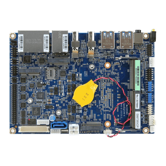
Page 17: Product Overview
User’s Manual 2.1 Product Overview ECM-TGU-B1 User’s Manual 17... -
Page 18: Jumper And Connector List
Matching Connector: JST PHR-5 JCPU_FAN1 CPU fan connector 4 x 1 wafer, pitch 2.54mm JCOM1 Serial Port 1 connector 5 x 2 header, pitch 2.00mm JCOM2 Serial Port 2 connector 5 x 2 header, pitch 2.00mm 18 ECM-TGU-B1 User’s Manual... - Page 19 6 x 2 header, pitch 2.00mm N_SIM1 SIM card slot J_N_SIM1 SIM card slot 10 x 1 FPC, pitch 0.50 mm JAMP1 Amp Connector 4 x 1 wafer, pitch 2.00mm EDP1 EDP connector 40 x 1 wafer, pitch 0.50mm ECM-TGU-B1 User’s Manual 19...
-
Page 20: Setting Jumpers & Connectors
ECM-TGU-B1 User’s Manual 2.3 Setting Jumpers & Connectors 2.3.1 Serial port 1/2 pin9 signal select (JRI1/2) Ring* +12V JRI2 JRI1 * Default 2.3.2 Clear CMOS (JRTC1) Normal* Clear CMOS * Default 20 ECM-TGU-B1 User’s Manual... -
Page 21: At/Atx Input Power Select (Jat1)
User’s Manual 2.3.3 AT/ATX Input power select (JAT1) * Default 2.3.4 LCD inverter connector (JBKL1) Signal +12V BKLEN VBRIGHT ECM-TGU-B1 User’s Manual 21... -
Page 22: Serial Port 1 Connector (Jcom1)
2.3.5 Serial port 1 connector (JCOM1) Signal PIN PIN Signal COM_DCD#_TXN_1 COM_RXD_TXP_1 COM_TXD_RXP_1 COM_DTR#_RXN_1 COM_DSR#_1 COM_RTS#_1 COM_CTS#_1 +V12S_COM_RI#_1 2.3.6 Serial port 2 connector (JCOM2) Signal PIN PIN Signal COM_DCD#_TXN_2 COM_RXD_TXP_2 COM_TXD_RXP_2 COM_DTR#_RXN_2 COM_DSR#_2 COM_RTS#_2 COM_CTS#_2 +V12S_COM_RI#_2 22 ECM-TGU-B1 User’s Manual... -
Page 23: Serial Port 3-6 Connector (Jcom3_6)
Signal PIN PIN Signal COM_DCD#_3 COM_RXD_3 COM_TXD_3 COM_DTR#_3 COM_DSR#_3 COM_RTS#_3 COM_CTS#_3 COM_RI#_3 COM_DCD#_4 COM_RXD_4 COM_TXD_4 COM_DTR#_4 COM_DSR#_4 COM_RTS#_4 COM_CTS#_4 COM_RI#_4 COM_DCD#_5 COM_RXD_5 COM_TXD_5 COM_DTR#_5 COM_DSR#_5 COM_RTS#_5 COM_CTS#_5 COM_RI#_5 COM_DCD#_6 COM_RXD_6 COM_TXD_6 COM_DTR#_6 COM_DSR#_6 COM_RTS#_6 COM_CTS#_6 COM_RI#_6 ECM-TGU-B1 User’s Manual 23... -
Page 24: Cpu Fan Connector (Jcpu_Fan1)
ECM-TGU-B1 User’s Manual 2.3.8 CPU fan connector (JCPU_FAN1) Signal +12V CPUFAN_IN CPUFAN_OUT 2.3.9 General purpose I/O connector (JDIO1) Signal PIN PIN Signal DIO_GP20 DIO_GP10 DIO_GP21 DIO_GP11 DIO_GP22 DIO_GP12 DIO_GP23 DIO_GP13 SMB_SCL_S0 SMB_SDA_S0 24 ECM-TGU-B1 User’s Manual... -
Page 25: Sata Power Connector (Jsata_Pwr1)
User’s Manual 2.3.10 SATA Power connector (JSATA_PWR1) Signal +12V 2.3.11 Power connector (PWR1) Signal Signal +24V +24V ECM-TGU-B1 User’s Manual 25... -
Page 26: Lvds Connector (Jlvds1)
10 LVDS_A_DATA_P_0 LVDS_A_DATA_N_1 11 12 LVDS_A_DATA_N_0 LVDS_A_DATA_P_3 15 16 LVDS_A_DATA_P_2 LVDS_A_DATA_N_3 17 18 LVDS_A_DATA_N_2 LVDS_B_DATA_P_1 21 22 LVDS_B_DATA_P_0 LVDS_B_DATA_N_1 23 24 LVDS_B_DATA_N_0 LVDS_B_DATA_P_3 27 28 LVDS_B_DATA_P_2 LVDS_B_DATA_N_3 29 30 LVDS_B_DATA_N_2 LVDS_B_CLK_P LVDS_A_CLK_P LVDS_B_CLK_N LVDS_A_CLK_N +12V +12V 26 ECM-TGU-B1 User’s Manual... -
Page 27: Usb2.0 Connector (Jusb56)
User’s Manual 2.3.13 USB2.0 connector (JUSB56) Signal PIN PIN Signal +5VSB +5VSB USB_R_DN5 USB_R_DN6 USB_R_DP5 USB_R_DP6 2.3.14 USB2.0 connector (JUSB78) Signal PIN PIN Signal +5VSB +5VSB USB_R_DN7 USB_R_DN8 USB_R_DP7 USB_R_DP8 ECM-TGU-B1 User’s Manual 27... -
Page 28: Battery Connector (Jbat1)
ECM-TGU-B1 User’s Manual 2.3.15 Battery connector (JBAT1) Signal +RTCBAT 2.3.16 LPC connector (JLPC1) Signal PIN PIN Signal LPC_AD0 +3.3V LPC_AD1 RST_TPM# LPC_AD2 LPC_LFRAME# LPC_AD3 CLK_24M_80 LPC_SERIRQ 28 ECM-TGU-B1 User’s Manual... -
Page 29: Front Panel Connector (Jfp1)
User’s Manual 2.3.17 Front Panel connector (JFP1) Signal PIN PIN Signal HDD_LED_P PWR_LED_P HDD_LED# PWR_LED# PM_SYSRST# PWRBTN_IN# 2.3.18 PC Buzzer connector (JBZ1) Signal SOC_SPKR_R ECM-TGU-B1 User’s Manual 29... -
Page 30: Amp Connector (Jamp1)
ECM-TGU-B1 User’s Manual 2.3.19 AMP connector (JAMP1) Signal AMP_LOUT+ AMP_LOUT- AMP_ROUT+ AMP_ROUT- 2.3.20 BIOS SPI connector (JBIOS_EC1) Signal PIN PIN Signal +V3.3A_SPI SPI_CS0#_ROM SPI_CLK_ROM SPI_MISO_ROM SPI_MOSI_ROM SPI_HOLD#_ROM SPI_WP#_ROM EC_SMCLK_DEBUG 10 EC_SMDAT_DEBUG 30 ECM-TGU-B1 User’s Manual... -
Page 31: Audio Connector (Jaudio1)
HD_AGND HD_AGND LINE1-R-IN LINE1-L-IN MIC1-R-IN MIC1-L-IN FRONT-JD LINE1-JD MIC1-JD HD_AGND 2.3.21.1 Signal Description – Audio connector (JAUDIO1) Signal Signal Description LINE1-JD AUDIO IN (LINE_RIN/LIN)sense pin FRONT-JD AUDIO Out(ROUT/LOUT) sense pin MIC1-JD MIC IN (MIC_RIN/LIN) sense pin ECM-TGU-B1 User’s Manual 31... -
Page 32: Sim Card Slot (J_N_Sim1)
ECM-TGU-B1 User’s Manual 2.3.22 SIM card slot (J_N_SIM1) Signal N_SIM_CD_R UIM_DATA_R UIM_CLK_R +VPP_SIM_1 UIM_RESET# +VCC_SIM 32 ECM-TGU-B1 User’s Manual... -
Page 33: Edp Connector (Edp1)
User’s Manual 2.3.23 EDP connector (EDP1) Signal eDP_TXN_0 eDP_TXP_0 eDP_AUX_P eDP_AUX_N +3.3V +3.3V +3.3V +3.3V Signal eDP_TXN_3 eDP_TXP_3 eDP_HPD_R eDP_TXN_2 eDP_TXP_2 eDP_TXN_1 eDP_BKLTEN_R eDP_TXP_1 eDP_VBRIGHT eDP_CTRL_CLK eDP_CTRL_DATA +12V +12V +12V +12V ECM-TGU-B1 User’s Manual 33... -
Page 34: Bios Setup
ECM-TGU-B1 User’s Manual 3.BIOS Setup 34 ECM-TGU-B1 User’s Manual... -
Page 35: Introduction
If the message disappears before you respond and you still wish to enter Setup, restart the system to try again by turning it OFF then ON or pressing the "RESET" button on the system case. You may also restart by simultaneously pressing <Ctrl>, <Alt>, and <Delete> keys. ECM-TGU-B1 User’s Manual 35... -
Page 36: Using Setup
Note: Some of the navigation keys differ from one screen to another. To Display a Sub Menu Use the arrow keys to move the cursor to the sub menu you want. Then press <Enter>. A “” pointer marks all sub menus. 36 ECM-TGU-B1 User’s Manual... -
Page 37: Getting Help
BIOS Vendor and your systems manufacturer to provide the absolute maximum performance and reliability. Even a seemingly small change to the chipset setup has the potential for causing you to use the override. ECM-TGU-B1 User’s Manual 37... -
Page 38: Bios Setup
<Enter> to accept and enter the sub-menu. 3.6.1 Main Menu This section allows you to record some basic hardware configurations in your computer and set the system clock. 38 ECM-TGU-B1 User’s Manual... -
Page 39: System Language
Visit the Avalue website (www.avalue.com.tw) to download the latest product and BIOS information. 3.6.2 Advanced Menu This section allows you to configure your CPU and other system devices for basic operation through the following sub-menus. ECM-TGU-B1 User’s Manual 39... -
Page 40: Connectivity Configuration
Otherwise Disable Integrated CNVi Mode Integrated solution (CNVi) will be enabled; [Disable Auto Detection[Default] Integrated] disables Integrated Solution. NOTE: When CNVi is present, the GPIO pins that are used for radio. 40 ECM-TGU-B1 User’s Manual... -
Page 41: Cpu Configuration
Item Options Description When enabled, a VMM can utilize the additional Intel (VMX) Virtualization Disabled hardware capabilities provided by Vanderpool Technology Enabled[Default] Technology. All[Default] Number of cores to enable in each processor Active Processor Cores package. ECM-TGU-B1 User’s Manual 41... -
Page 42: Power & Performance
Allows more than two frequency ranges to be Intel® SpeedStep™ Disabled supported. Eanble/Disable Intel® Speed Shift Technology Intel® Speed Shift Enabled[Default], support. Enabling will expose the CPPC v2 interface to Technology Disabled allow for hardware controlled P-states. 42 ECM-TGU-B1 User’s Manual... -
Page 43: Pch-Fw Configuration
Disabled enabled). Enabled[Default], C States Enable/Disable CPU Power Management. Disabled Enabled[Default], Enable/Disable C1E. When enabled, CPU will switch Enhanced C-States Disabled to minimum speed when all cores enter C-State. 3.6.2.4 PCH-FW Configuration 3.6.2.4.1 Firmware Update Configuration ECM-TGU-B1 User’s Manual 43... -
Page 44: Trusted Computing
3.6.2.5 Trusted Computing Item Options Description Enables or Disables BIOS support for security device. Disable, Security Device Support O.S. will not show Security Device. TCG EFI protocol Enable[Default] and INT1A interface will not be available. 3.6.2.6 APCI Settings 44 ECM-TGU-B1 User’s Manual... -
Page 45: Super Io Configuration
Set Parameters of Serial Port 3 (COMC). Serial Port 4 Configuration Set Parameters of Serial Port 4 (COMD). Serial Port 5 Configuration Set Parameters of Serial Port 5 (COME). Serial Port 6 Configuration Set Parameters of Serial Port 6 (COMF). ECM-TGU-B1 User’s Manual 45... -
Page 46: Serial Port 1 Configuration
3.6.2.7.1 Serial Port 1 Configuration Item Option Description Enabled[Default], Serial Port Enable or Disable Serial Port (COM). Disabled UART 232[Default] UART 232 422 485 UART 422 Change the Serial Port as RS232/422/485. UART 485 3.6.2.7.2 Serial Port 2 Configuration 46 ECM-TGU-B1 User’s Manual... -
Page 47: Serial Port 3 Configuration
UART 232 422 485 UART 422 Change the Serial Port as RS232/422/485. UART 485 3.6.2.7.3 Serial Port 3 Configuration Item Option Description Enabled[Default], Serial Port Enable or Disable Serial Port (COM). Disabled 3.6.2.7.4 Serial Port 4 Configuration ECM-TGU-B1 User’s Manual 47... -
Page 48: Serial Port 5 Configuration
Item Option Description Enabled[Default], Serial Port Enable or Disable Serial Port (COM). Disabled 3.6.2.7.5 Serial Port 5 Configuration Item Option Description Enabled[Default], Serial Port Enable or Disable Serial Port (COM). Disabled 3.6.2.7.6 Serial Port 6 Configuration 48 ECM-TGU-B1 User’s Manual... -
Page 49: Hw Monitor
User’s Manual Item Option Description Enabled[Default], Serial Port Enable or Disable Serial Port (COM). Disabled 3.6.2.8 HW Monitor Item Options Description Enabled, Smart Fan Function Enables or Disables Smart Fan. Disabled[Default] 3.6.2.9 S5 RTC Wake Settings ECM-TGU-B1 User’s Manual 49... -
Page 50: Serial Port Console Redirection
Select Dynamic Time, System will wake on the current time Dynamic Time + Increase minute(s). 3.6.2.10 Serial Port Console Redirection Item Options Description Disabled[Default], Console Redirection Console Redirection Enable or Disable. Enabled Disabled[Default], Console Redirection EMS Console Redirection Enable or Disable. Enabled 50 ECM-TGU-B1 User’s Manual... -
Page 51: Legacy Console Redirection Settings
Legacy OS and Legacy OPROM Messages. 3.6.2.11 USB Configuration The USB Configuration menu helps read USB information and configures USB settings. Item Options Description 1 sec The time-out value for Control, Bulk, and USB transfer time-out 5 sec Interrupt transfers. ECM-TGU-B1 User’s Manual 51... -
Page 52: Network Stack Configuration
Optical drives are emulated as ‘CDROM’, drives with no media will be Hard Disk CD-ROM emulated according to a drive type. 3.6.2.12 Network Stack Configuration Item Options Description Enabled Network Stack Enable/Disable UEFI Network Stack. Disabled[Default] 52 ECM-TGU-B1 User’s Manual... -
Page 53: Nvme Configuration
User’s Manual 3.6.2.13 NVMe Configuration 3.6.3 Chipset ECM-TGU-B1 User’s Manual 53... -
Page 54: System Agent (Sa) Configuration
ECM-TGU-B1 User’s Manual 3.6.3.1 System Agent (SA) Configuration Item Option Description Enabled[Default] VT-d VT-d capability. Disabled 3.6.3.1.1 Memory Configuration 54 ECM-TGU-B1 User’s Manual... -
Page 55: Graphics Configuration
Description Auto[Default] Select which of IGFX/PEG/PCI Graphics device should Primary Display IGFX be Primary Display Or select HG for Hybrid Gfx. 3.6.3.1.3 VMD setup menu Item Option Description Enabled Enable VMD controller Enable/Disable VMD controller. Disabled[Default] ECM-TGU-B1 User’s Manual 55... -
Page 56: Pch-Io Configuration
ECM-TGU-B1 User’s Manual 3.6.3.2 PCH-IO Configuration 3.6.3.2.1 PCI Express Configuration 56 ECM-TGU-B1 User’s Manual... - Page 57 L0s State AUTO – BIOS auto ASPM configure DISABLE – Disables ASPM. L0sL1 Auto Disabled, L1 Substates L1.1 PCI Express L1 Substates settings. L1.1 & L1.2[Default] Auto[Default] Gen1 PCIe Speed Configure PCIe Speed. Gen2 Gen3 ECM-TGU-B1 User’s Manual 57...
- Page 58 L0s State AUTO – BIOS auto ASPM configure DISABLE – Disables ASPM. L0sL1 Auto Disabled, L1 Substates L1.1 PCI Express L1 Substates settings. L1.1 & L1.2[Default] Auto[Default] Gen1 PCIe Speed Configure PCIe Speed. Gen2 Gen3 58 ECM-TGU-B1 User’s Manual...
- Page 59 L0s State AUTO – BIOS auto ASPM configure DISABLE – Disables ASPM. L0sL1 Auto Disabled, L1 Substates L1.1 PCI Express L1 Substates settings. L1.1 & L1.2[Default] Auto[Default] Gen1 PCIe Speed Configure PCIe Speed. Gen2 Gen3 ECM-TGU-B1 User’s Manual 59...
- Page 60 L0s State AUTO – BIOS auto ASPM configure DISABLE – Disables ASPM. L0sL1 Auto Disabled, L1 Substates L1.1 PCI Express L1 Substates settings. L1.1 & L1.2[Default] Auto[Default] Gen1 PCIe Speed Configure PCIe Speed. Gen2 Gen3 60 ECM-TGU-B1 User’s Manual...
- Page 61 L0s State AUTO – BIOS auto ASPM configure DISABLE – Disables ASPM. L0sL1 Auto Disabled, L1 Substates L1.1 PCI Express L1 Substates settings. L1.1 & L1.2[Default] Auto[Default] Gen1 PCIe Speed Configure PCIe Speed. Gen2 Gen3 ECM-TGU-B1 User’s Manual 61...
-
Page 62: Sata And Rst Configuration
3.6.3.2.2 SATA And RST Configuration Item Options Description Enabled[Default] SATA Controller(s) Enable/Disable SATA Device. Disabled, Enabled[Default] Port 0 Enable or Disable SATA Port. Disabled Enabled[Default] Port 1 Enable or Disable SATA Port. Disabled 3.6.3.2.3 HD Audio Configuration 62 ECM-TGU-B1 User’s Manual... -
Page 63: Board & Panel Configuration
1920x1080 24/2 1680x1050 24/2 Panel Brightness Control BIOS[Default] Panel Brightness Control Method. 1.BIOS Method OS Driver 2.OS Driver. Select Panel(eDP/LVDS) back light PWM Panel Brightness duty. 100%[Default] Panel Back Light PWM 200[Default] Select Panel(eDP/LVDS) back light PWM ECM-TGU-B1 User’s Manual 63... -
Page 64: Show Dmi Info
Select WatchDog. 1 min 2 min 10 min 30 min Disabled Enable/Disabled USB Standby Power USB Standby Power(Rear) Enabled[Default] during S3/S4/S5. Disabled Enable/Disabled USB Standby Power USB Standby Power(Internal) Enabled[Default] during S3/S4/S5. 3.6.3.3.1 SHOW DMI INFO 64 ECM-TGU-B1 User’s Manual... -
Page 65: Security
User’s Manual 3.6.4 Security Administrator Password Set setup Administrator Password User Password Set User Password ECM-TGU-B1 User’s Manual 65... -
Page 66: Secure Boot
Platform Key(PK) is enrolled and the System is in User Enabled mode. The mode change requires platform reset. Secure Boot mode selector: Standard/Custom. In Standard Secure Boot Mode Custom mode Secure Boot Variables can be configured Custom[Default] without authentication. 66 ECM-TGU-B1 User’s Manual... -
Page 67: Key Management
User’s Manual 3.6.4.1.1 Key Management Item Option Description Install factory default Secure Boot keys after Disabled[Default] Factory Key Provision the platform reset and while the System is in Enabled Setup mode. 3.6.5 Boot ECM-TGU-B1 User’s Manual 67... -
Page 68: Save And Exit
Enables or disables boot with initialization of a Disabled[Default] Fast Boot minimal set of devices required to launch active Enabled boot option. Has no effect for BBS boot optios. Boot Option #1/2 Set the system boot order. 3.6.6 Save and exit 68 ECM-TGU-B1 User’s Manual... -
Page 69: Save Changes And Reset
This option restores all BIOS settings to the factory default. This option is useful if the controller exhibits unpredictable behavior due to an incorrect or inappropriate BIOS setting. 3.6.6.4 Launch EFI Shell from filesystem device Attempts to Launch EFI Shell application (Shellx64.efi) from one of the available filesystem devices. ECM-TGU-B1 User’s Manual 69... -
Page 70: Drivers Installation
ECM-TGU-B1 User’s Manual 4. Drivers Installation Note: Installation procedures and screen shots in this section are for your reference and may not be exactly the same as shown on your screen. 70 ECM-TGU-B1 User’s Manual... -
Page 71: Install Chipset Driver
Windows 10 operation system. If the warning message appears while the installation process, click Continue to go on. Step 3. Click Install. Step1. Click Next. Step 4. Complete setup. Step 2. Click Accept. ECM-TGU-B1 User’s Manual 71... -
Page 72: Install Vga Driver
If the warning message appears while the installation process, click Continue to go on. Step 3. Click Start. Step 1. Click Begin installation. Step 4. Click Reboot now. Step 2. Click Next to accept license agreement. 72 ECM-TGU-B1 User’s Manual... -
Page 73: Install Me Driver
If the warning message appears while the installation process, click Continue to go on. Step 3. Click Next. Step 4. Click Finish to complete setup. Step 1. Click Next to continue setup. Step 2. Click Next. ECM-TGU-B1 User’s Manual 73... -
Page 74: Install Lan Driver
Windows 10 operation system. If the warning message appears while the installation process, click Continue to go on. Step 1. Click OK to continue installation. Step 2. Complete setup. 74 ECM-TGU-B1 User’s Manual... -
Page 75: Install Audio Driver
Windows 10 operation system. If the warning message appears while the installation process, click Continue to go on. Step 1. Click Next to continue installation. Step 2. Click Finish to complete setup. ECM-TGU-B1 User’s Manual 75... -
Page 76: Mechanical Drawing
ECM-TGU-B1 User’s Manual 5. Mechanical Drawing 76 ECM-TGU-B1 User’s Manual... - Page 77 User’s Manual Unit: mm ECM-TGU-B1 User’s Manual 77...
- Page 78 ECM-TGU-B1 User’s Manual Thermal Solutions: ECM-TGU-B1 standard package with heatsink (BIOS TDP: 15W), we also design cooler (BIOS TDP: 28W) solution for customer optional purchase. 78 ECM-TGU-B1 User’s Manual...
Need help?
Do you have a question about the ECM-TGU-B1 and is the answer not in the manual?
Questions and answers