
Related Manuals for Avalue Technology EBM-BSW


Summary of Contents for Avalue Technology EBM-BSW
- Page 1 EBM-BSW Intel® Core™ SoC Processor 5.25” Mini Module User’s Manual Ed – 22 June 2015 Part No. E2047582500R...
- Page 2 Disclaimer Avalue Technology Inc. reserves the right to make changes, without notice, to any product, including circuits and/or software described or contained in this manual in order to improve design and/or performance. Avalue Technology assumes no responsibility or liability for the...
- Page 3 Applications that are described in this manual are for illustration purposes only. Avalue Technology Inc. makes no representation or warranty that such application will be suitable for the specified use without further testing or modification.
- Page 4 A product returned without proof of the purchase date is not eligible for warranty service. Write the RMA number visibly on the outside of the package and ship it prepaid to your dealer. 4 EBM-BSW User’s Manual...
-
Page 5: Table Of Contents
AMPLIFIER_R (JAMP_R)....................28 2.3.21 AMPLIFIER_L (AMP_L) ....................28 2.3.22 SPI connector (JSPI2) ....................... 29 2.3.23 EC Debug connector (JECDBUG) ..................29 2.3.24 PS/2 keyboard & mouse connector (JKBMS) ..............30 2.3.25 RTC Battery connector (JRTC) ..................30 EBM-BSW User’s Manual... - Page 6 Install Nuvoton Driver ..................51 Install TXE Driver ..................... 52 Install VGA Driver .................... 53 Install Audio Driver (For Realtek ALC233) ............54 Install Ethernet Driver ..................55 Install Serial IO Driver..................56 5. Mechanical Drawing ..................... 57 6 EBM-BSW User’s Manual...
-
Page 7: Getting Started
1.2 Packing List Before you begin installing your single board, please make sure that the following materials have been shipped: 1 x EBM-BSW Intel® Core™ SoC Processor 5.25” Mini Module 1 x Driver/Utility DVD-ROM ... -
Page 8: Document Amendment History
EBM-BSW User’s Manual 1.3 Document Amendment History Revision Date Comment June 2015 Avalue Initial Release 8 EBM-BSW User’s Manual... -
Page 9: Manual Objectives
We strongly recommend that you study this manual carefully before attempting to set up EBM-BSW or change the standard configurations. Whilst all the necessary information is available in this manual we would recommend that unless you are confident, you contact your supplier for guidance. -
Page 10: System Specifications
1 x 1 x 4 pin header w/ 2.54mm pitch (Optional) Buzzer Onboard CMOS Battery Cable type battery CR-2032; 1 x 1 x 2 pin wafer w/ 1.25mm pitch Audio 2 x 1 x 2 wafer w/2.0mm pitch for AMP 10 EBM-BSW User’s Manual... - Page 11 Green indicator: power-on Yellow indicator: HDD active Mechanical & Environmental Power +12V~26V (11.4V~26V) Requirement Single power ATX Support S0, S3, S4, S5 ACPI ACPI 5.0 Compliant Power Type AT / ATX Operating 0°C ~ 60°C (32°F ~ 140°F) EBM-BSW User’s Manual 11...
- Page 12 Size (L x W) 8" x 5.75" (203mm x 146mm) Weight 0.25 kg S5 Under 0.5W Certifications Certification Information FCC Class B Software Support OS Information Win8, Win7, Linux Note: Specifications are subject to change without notice. 12 EBM-BSW User’s Manual...
-
Page 13: Architecture Overview-Block Diagram
User’s Manual 1.6 Architecture Overview—Block Diagram The following block diagram shows the architecture and main components of EBM-BSW. EBM-BSW User’s Manual 13... -
Page 14: Hardware Configuration
EBM-BSW User’s Manual 2. Hardware Configuration 14 EBM-BSW User’s Manual... -
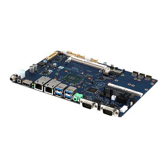
Page 15: Product Overview
User’s Manual 2.1 Product Overview EBM-BSW User’s Manual 15... -
Page 16: Jumper And Connector List
Serial port 1/2 – RS232/ 422/ 485 mode JP1/2 4 x 3 header, pitch 2.00mm select Connectors Label Function Note JCPUFAN CPU fan connector 4 x 1 header, pitch 2.54mm 5 x 1 wafer, pitch 2.00mm JBKL1 LCD Inverter connector 16 EBM-BSW User’s Manual... - Page 17 SATA Power connector JSATA1 Serial ATA connector 1 JSATA2 Serial ATA connector 2 JSIM1 SIM card slot JHDMI HDMI connector Audio line-out connector LCD Backlight VR/Push Up/Push Down 2 x 3 wafer, pitch 2.00mm JBLKCTL connector EBM-BSW User’s Manual 17...
-
Page 18: Setting Jumpers & Connectors
In Serial Port 1 mode RS-232 RS-422 RS-485 In Serial Port 2 mode RS-232 RS-422 RS-485 AT SEL ATX SEL Touch off Touch on 2.3.2 Serial port 1/ 2 pin9 signal select (JRI1/ JRI2) Ring* JRI2 JRI1 +12V * Default 18 EBM-BSW User’s Manual... -
Page 19: Serial Port 1/ 2 Rs-232/ 422/ 485 Mode Select (Jp1/ Jp2)
User’s Manual 2.3.3 Serial port 1/ 2 RS-232/ 422/ 485 mode select (JP1/ JP2) RS-232* RS-422/ 485 * Default 2.3.4 LCD brightness DC/PWM mode select (JVR1) PWM Mode* DC Mode * Default EBM-BSW User’s Manual 19... -
Page 20: Lcd Brightness Pwm Voltage Select (Jpwm)
EBM-BSW User’s Manual 2.3.5 LCD brightness PWM voltage select (JPWM) 3.3V* * Default 2.3.6 Clear CMOS (JRST) Normal* Clear CMOS * Default 20 EBM-BSW User’s Manual... -
Page 21: Lcd Inverter Connector (Jbkl1)
For inverters with adjustable Backlight function, it is possible to control the LCD brightness through the VR signal controlled by JBLKCTL. Please see the JBLKCTL section for detailed circuitry information. 2.3.8 CPU fan connector (JCPUFAN) Signal FAN_PWM1 EC_TACH0_R +12V EBM-BSW User’s Manual 21... -
Page 22: Serial Port 3/4/5 Connector (Jcom3/Jcom4/Jcom5)
Serial port 3/4/5 connector (JCOM3/JCOM4/JCOM5) JCOM3 JCOM4 JCOM5 Signal PIN PIN Signal COM_RXD# COM_DCD# COM_DTR# COM_TXD COM_DSR# COM_CTS# COM_RTS# COM_RI# 2.3.10 Front Panel connector (JLED1) Signal PIN PIN Signal PWRBTN# +3VALW LAN_LED1_ACT# +3VALW LAN_LED0_ACT# +5VS HDD_LED# +5VALW PWR_LED_FP# 22 EBM-BSW User’s Manual... -
Page 23: General Purpose I/O Connector (Jdio)
General purpose I/O connector (JDIO) Signal PIN PIN Signal +V5S_DIO SMB_DATA_9555 18 SMB_CLK_9555 DIO_GP27 DIO_GP17 DIO_GP26 DIO_GP16 DIO_GP25 DIO_GP15 DIO_GP24 DIO_GP14 DIO_GP23 DIO_GP13 DIO_GP22 DIO_GP12 DIO_GP21 DIO_GP11 DIO_GP20 DIO_GP10 2.3.12 Touch panel connector (JTOUCH) Signal THX+ THX- THPROBE_R THY+ THY- EBM-BSW User’s Manual 23... -
Page 24: Sata Power Connector (Jspwr1)
EBM-BSW User’s Manual 2.3.13 SATA Power connector (JSPWR1) Signal 2.3.14 Power connector (JPWR1) Signal Signal VIN_IN VIN_IN 24 EBM-BSW User’s Manual... -
Page 25: Lcd Backlight Vr/Push Up/Push Down Connector (Jblkctl)
User’s Manual 2.3.15 LCD Backlight VR/Push Up/Push Down connector (JBLKCTL) Signal PIN PIN Signal BLK_VR_MOD BLK_BRI_UP BLK_BRI_DN 2.3.16 LPC connector (JLPC1) Signal PIN PIN Signal LPC_SERIRQ LPC_PORT80_CLK LPC_AD3 LPC_FRAME# LPC_AD2 LPC_PORT80_RST# LPC_AD1 LPC_AD0 EBM-BSW User’s Manual 25... -
Page 26: Lvds Connector (Jlvds)
EBM-BSW User’s Manual 2.3.17 LVDS connector (JLVDS) Signal PIN PIN Signal +12V +12V +12V +12V LVDS_TXOUT_CLK1N LVDS_TXOUT_CLK2N LVDS_TXOUT_CLK1P LVDS_TXOUT_CLK2P LVDS_TXOUT_N6 LVDS_TXOUT_N7 LVDS_TXOUT_P6 LVDS_TXOUT_P7 LVDS_TXOUT_N4 LVDS_TXOUT_N5 LVDS_TXOUT_P4 LVDS_TXOUT_P5 LVDS_TXOUT_N2 LVDS_TXOUT_N3 LVDS_TXOUT_P2 LVDS_TXOUT_P3 LVDS_TXOUT_N0 LVDS_TXOUT_N1 LVDS_TXOUT_P0 LVDS_TXOUT_P1 +3.3V +3.3V 26 EBM-BSW User’s Manual... -
Page 27: Usb Connector (Jusb23)
User’s Manual 2.3.18 USB connector (JUSB23) Signal PIN PIN Signal USB2DN_DP2_R USB2DN_DP3_R USB2DN_DM2_R USB2DN_DM3_R 2.3.19 USB connector (JUSB4) Signal USB2DN_DP4_R USB2DN_DM4_R EBM-BSW User’s Manual 27... -
Page 28: Amplifier_R (Jamp_R)
EBM-BSW User’s Manual 2.3.20 AMPLIFIER_R (JAMP_R) Signal SPK_R+ SPK_R- 2.3.21 AMPLIFIER_L (AMP_L) Signal SPK_L+ SPK_L- 28 EBM-BSW User’s Manual... -
Page 29: Spi Connector (Jspi2)
User’s Manual 2.3.22 SPI connector (JSPI2) Signal PIN PIN Signal SPI_HOLD# SPI_MOSI SPI_MISO SPI_CLK SPI_CS#0 +1.8V 2.3.23 EC Debug connector (JECDBUG) Signal PIN PIN Signal KSO6 KSO5 KSO14 KSO13 KSO12 KSO0 EBM-BSW User’s Manual 29... -
Page 30: Ps/2 Keyboard & Mouse Connector (Jkbms)
EBM-BSW User’s Manual 2.3.24 PS/2 keyboard & mouse connector (JKBMS) Signal PIN PIN Signal KBDT KBCK KBVCC MSDT MSCK 2.3.25 RTC Battery connector (JRTC) Signal +RTCBATT 30 EBM-BSW User’s Manual... -
Page 31: Ebm-Bsw User's Manual 31
User’s Manual 3.BIOS Setup EBM-BSW User’s Manual 31... -
Page 32: Introduction
If the message disappears before you respond and you still wish to enter Setup, restart the system to try again by turning it OFF then ON or pressing the "RESET" button on the system case. You may also restart by simultaneously pressing <Ctrl>, <Alt>, and <Delete> keys. 32 EBM-BSW User’s Manual... -
Page 33: Using Setup
Note: Some of the navigation keys differ from one screen to another. To Display a Sub Menu Use the arrow keys to move the cursor to the sub menu you want. Then press <Enter>. A “” pointer marks all sub menus. EBM-BSW User’s Manual 33... -
Page 34: Getting Help
BIOS Vendor and your systems manufacturer to provide the absolute maximum performance and reliability. Even a seemingly small change to the chipset setup has the potential for causing you to use the override. 34 EBM-BSW User’s Manual... -
Page 35: Bios Setup
Note: The BIOS setup screens shown in this chapter are for reference purposes only, and may not exactly match what you see on your screen. Visit the Avalue website (www.avalue.com.tw) to download the latest product and BIOS information. EBM-BSW User’s Manual 35... -
Page 36: Advanced Menu
30 min 1024x768 24/1[Default] 800x600 18/1 1024x768 18/1 1366x768 18/1 1024x600 18/1 1280x800 18/1 Panel Type Select 1920x1200 24/2 Select Panel Type for display. 640x480 18/1 800x480 18/1 1920x1080 18/2 1280x1024 24/2 1440x900 18/2 1600x1200 24/2 36 EBM-BSW User’s Manual... -
Page 37: Sata Configuration
User’s Manual 1366x768 24/1 1920x1080 24/2 1680x1050 24/2 3.6.2.1 SATA Configuration Item Options Description Disabled, SATA Controller SATA Controller. Enabled[Default] Gen1 SATA Interface Speed Gen2 Select SATA Interface Speed. Gen3[Default] EBM-BSW User’s Manual 37... -
Page 38: Pci Express Configuration
PCIE port 1, another PCIE port will be Enabled[Default], disabled. Disabled[Default] PCI Express Active State Power Management ASPM settings. L0sL1 Disabled[Default] L1.1 & L1.2 L1 Substates PCI Express L1 Substates settings. L1.1 L1.2 Auto[Default] PCIe Speed Gen 1 Configure PCIe Speed. Gen 2 38 EBM-BSW User’s Manual... -
Page 39: Console Redirection
3.6.2.3 Console Redirection Item Options Description Enabled Console Serial Redirect Console Redirection Enable or Disable. Disabled[Default] Serial Port Console Redirection Table: Disabled[Default] ACPI SPCR Table Enabled this feature, the SPCR table will be Enabled add-into ACPI Tables. EBM-BSW User’s Manual 39... - Page 40 Set Console Redirection parity bits. 1 Bit[Default] Stop Bits Set Console Redirection stop bits. 2 Bits None[Default] Flow Control RTS/CTS Set Console Redirection flow control type. XON/XOFF 0 Second Information Wait Time 2 Second Information Wait Time. 5 Second[Default] 40 EBM-BSW User’s Manual...
-
Page 41: Com2/3/4/5
Disabled. Disabled Use Global Setting Use Global Setting Enabled or Disabled. Enabled[Default] VT_100[Default] VT_100+ Terminal Type Set Console Redirection terminal type. VT_UTF8 PC_ANSI 115200[Default] 57600 38400 Baud Rate Set Console Redirection baud rate. 19200 9600 4800 EBM-BSW User’s Manual 41... -
Page 42: Rtc S5 Wake
Select wake up day of week. Every Day Disabled[Default] This is the help for the hour, minute second Time [00:00:00][Default] field. Valid range is from 0 to 23, 0 to 59, 0 to 59. INCREASE/REDUCE : +/-. 42 EBM-BSW User’s Manual... -
Page 43: Hardware Monitor
User’s Manual 3.6.2.6 Hardware Monitor 3.6.2.7 SIO NUVOTON5104D EBM-BSW User’s Manual 43... -
Page 44: Brightness Control
EBM-BSW User’s Manual 3.6.2.8 Brightness Control Item Options Description Brightness Control LCD Brightness is controlled by BIOS or VR. BIOS[Default] Backlight brightness Backlight brightness percentage. 100%[Default] 200[Default] LVDS Back Light PWM LVDS Back Light PWM Frequency. Frequency 44 EBM-BSW User’s Manual... -
Page 45: Security
Enable/Disable TPM Function. This option will TPM Operation Disable and Deactivate automatically return to No-Operation. Enable and Activate Set Supervisor Password. Install or Change the password and the length of Set Supervisor Password password must be greater than on character EBM-BSW User’s Manual 45... -
Page 46: Power
AC Loss Resume AC Loss Resume setting. Enabled Disabled Enable processor Turbo Mode(requires Turbo Mode Enabled[Default] EMTTM enabled too). Disabled USB Power USB Power on standby. Enabled[Default] Disabled Enable processor idle power saving C-States Enabled[Default] states (C-States). 46 EBM-BSW User’s Manual... -
Page 47: Boot
Quiet Boot Enabled[Default] Mode. Network Stack Support: Windows 8 Disabled[Default] Network Stack BitLocker Unlock UEFI IPv4/ IPv6 PXE Enabled Legacy PXE OPROM. First Position in Boot Order for Shell, Network Add Boot Options Auto[Default] and Removables. EBM-BSW User’s Manual 47... -
Page 48: Exit
3.6.6.3 Exit Discarding Changes Exit system setup and without saving your changes. 3.6.6.4 Load Optimal Defaults Load Optimal Defaults. 3.6.6.5 Load Custom Defaults Load Custom Defaults. 3.6.6.6 Save Custom Defaults Save Custom Defaults. 3.6.6.7 Discard Changes Discard Changes. 48 EBM-BSW User’s Manual... -
Page 49: Drivers Installation
User’s Manual 4. Drivers Installation Note: Installation procedures and screen shots in this section are for your reference and may not be exactly the same as shown on your screen. EBM-BSW User’s Manual 49... -
Page 50: Install Chipset Driver
Windows 8.1 operation system. If the warning message appears while the installation Step 3. Click Install. process, click Continue to go on. Step 4. Click Finish to complete setup. Step1. Click Next. Step 2. Click Accept. 50 EBM-BSW User’s Manual... -
Page 51: Install Nuvoton Driver
Step 3. Click Next. appears while the installation process, click Continue to go on. Step1. Click Next to start installation. Step 4. Click Install. Step 5. Click Finish to complete setup. Step 2. Click Next to proceed setup. EBM-BSW User’s Manual 51... -
Page 52: Install Txe Driver
If the warning message appears while the installation Step 3. Click Next to continue installation. process, click Continue to go on. Step 4. Click Finish to complete setup. Step1. Click Next to start installation. Step 2. Click Next. 52 EBM-BSW User’s Manual... -
Page 53: Install Vga Driver
Windows 8.1 operation system. Step 3. Click Next. Step 1. Click Next to continue installation. Step 4. Click Next. Step 5. Click Finish to complete setup. Step 2. Click Yes to accept license agreement. EBM-BSW User’s Manual 53... -
Page 54: Install Audio Driver (For Realtek Alc233)
\Driver_Audio\Realtek\ALC233\EBM-BSW_Audio. Note: The installation procedures and screen shots in this section are based on Windows 8.1 operation system. Step 1. Click Next to continue setup. Step 2. Click Finish to complete the setup. 54 EBM-BSW User’s Manual... -
Page 55: Install Ethernet Driver
\Driver_Gigabit\Realtek\RTL8119\EBM-BSW_LAN. Note: The installation procedures and screen shots in this section are based on Windows 8.1 operation system. Step 3. Click Finish to complete the setup. Step 1. Click Next. Step 2. Click Install to proceed. EBM-BSW User’s Manual 55... -
Page 56: Install Serial Io Driver
\Utility\EBM-BSW_Serial Note: The installation procedures and screen shots in this section are based on Windows 8.1 operation system. Step 1. Click Next to continue setup. Step 2. Click Finish to complete the setup. 56 EBM-BSW User’s Manual... -
Page 57: Mechanical Drawing
User’s Manual 5. Mechanical Drawing EBM-BSW User’s Manual 57... - Page 58 EBM-BSW User’s Manual Unit: mm 58 EBM-BSW User’s Manual...
- Page 59 User’s Manual Unit: mm EBM-BSW User’s Manual 59...
Need help?
Do you have a question about the EBM-BSW and is the answer not in the manual?
Questions and answers