Table of Contents

Related Manuals for Avalue Technology ESM-EHLC


Summary of Contents for Avalue Technology ESM-EHLC
- Page 1 ESM-EHLC PICMG COM.0 R3.0 Type 6 Compact module with on board Intel® Elkhart Lake series Platform User’s Manual Ed –31 May 2022 Copyright Notice Copyright 2022 Avalue Technology Inc., ALL RIGHTS RESERVED. Part No. E2047290400R...
- Page 2 Disclaimer Avalue Technology Inc. reserves the right to make changes, without notice, to any product, including circuits and/or software described or contained in this manual in order to improve design and/or performance. Avalue Technology assumes no responsibility or liability for the...
- Page 3 Applications that are described in this manual are for illustration purposes only. Avalue Technology Inc. makes no representation or warranty that such application will be suitable for the specified use without further testing or modification.
-
Page 4: Table Of Contents
2.3.3.1 Signal Description – COM Express Connector 2 (CN1B) ............30 2.3.3.1.1 USB3.0 Signals ........................30 2.3.3.1.2 DDI Signals .......................... 30 Installing Heatsink / Heat spreader ................. 31 BIOS Setup ........................ 33 Introduction ......................34 Starting Setup ......................34 4 ESM-EHLC User’s Manual... - Page 5 ESM-EHLC User’s Manual Using Setup ......................35 Getting Help ......................36 In Case of Problems ....................36 BIOS setup ......................37 3.6.1 Main Menu ............................37 3.6.1.1 System Language ........................38 3.6.1.2 System Date .......................... 38 3.6.1.3 System Time .......................... 38 3.6.2...
- Page 6 Install Chipset Driver ....................78 Install HID Driver ..................... 79 Install VGA Driver ....................80 Install Audio Driver ....................81 Install Ethernet Driver ....................82 Install ME Driver ...................... 84 Install SIO Driver ..................... 85 5. Mechanical Drawing ....................86 6 ESM-EHLC User’s Manual...
-
Page 7: Getting Started
1.2 Packing List Before you begin installing your single board, please make sure that the following materials have been shipped: 1 x ESM-EHLC COMe Module 1 x Desiccant (5g) 4 x Screws ... -
Page 8: Document Amendment History
ESM-EHLC User’s Manual 1.3 Document Amendment History Revision Date Comment May 2022 Avalue Initial Release 8 ESM-EHLC User’s Manual... -
Page 9: Manual Objectives
We strongly recommend that you study this manual carefully before attempting to set up ESM-EHLC series or change the standard configurations. Whilst all the necessary information is available in this manual we would recommend that unless you are confident, you contact your supplier for guidance. -
Page 10: System Specifications
(Redriver in carrier board to fine tune the signal of DP1.4). Spec. & Resolution eDP 1.3b(Optional): 4096x2160 @60Hz (Only support 4Lanes 2560x1440 & 2Lanes 1920x1080) LVDS(via eDP-to-LVDS): 1920x1080 @60Hz, LVDS via CH7511B VGA(via DP-to-VGA): 1920x1080 @60Hz, VGA via CH7517A (DP to VGA) 10 ESM-EHLC User’s Manual... - Page 11 40°C @ 95% Relative Humidity, Non-condensing Size (L x W) (Please consult product engineers for the 95 x 95 mm (3.74” x 3.74”) production feasibility if the size is larger than 410x360mm or smaller than 80x70mm) Weight 0.44lbs(0.2kg) ESM-EHLC User’s Manual 11...
- Page 12 Windows* 10 IoT Enterprise (64-bit), Linux Carrier Carrier: with EEV-EX16 B1 version Sample build included BOM1 & 2, BOM3 RD will adjust component and offer for Others testing Note: Specifications are subject to change without notice. 12 ESM-EHLC User’s Manual...
-
Page 13: Architecture Overview-Block Diagram
ESM-EHLC User’s Manual 1.6 Architecture Overview—Block Diagram The following block diagram shows the architecture and main components of ESM-EHLC. ESM-EHLC User’s Manual 13... -
Page 14: Hardware Configuration
ESM-EHLC User’s Manual 2. Hardware Configuration 14 ESM-EHLC User’s Manual... -
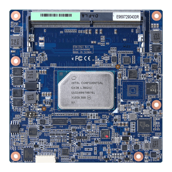
Page 15: Product Overview
ESM-EHLC User’s Manual 2.1 Product Overview ESM-EHLC User’s Manual 15... -
Page 16: Connector List
(Reserved for BIOS programming) 5 x 2 header, pitch 2.00mm BIOS_SPI1 CN1A COM Express connector 1 COM Express connector 2 CN1B SODIMM1 260-pin DDR4 SDRAM DIMM socket SODIMM2 260-pin DDR4 SDRAM DIMM socket AT/ATX mode selector 16 ESM-EHLC User’s Manual... -
Page 17: Setting Jumpers & Connectors
*Default 2.3.1.1 Signal Description –AT/ATX mode selection AT/ATX mode Description AT mode Auto power on, no need to press Power button to enable power on/off ATX mode Press the ATX power button to enable power on/off ESM-EHLC User’s Manual 17... -
Page 18: Com Express Connector 1 (Cn1A)
A100 B100 SER0_RX SER0_TX TYPE10# SPI_CS# TPM_PP VGA_I2C_DAT SPI_MOSI VGA_I2C_CK SPI_CLK VGA_VSYNC GPO0 VGA_HSYNC SPI_MISO VGA_BLU +3.3V_SPI VGA_GRN PCIE_CLK_REF- VGA_RED PCIE_CLK_REF+ BIOS_DIS1# CB_EDP_HDP +ATX5VSB +ATX5VSB GPI3 +ATX5VSB LVDS_I2C_DAT/EDP_AUX- A84 +ATX5VSB LVDS_BKLT_CTRL/ LVDS_I2C_CK/EDP_AUX+ EDP_BKLT_CTRL LVDS_A_CK-/EDP_TX3- LVDS_B_CK- LVDS_A_CK+/EDP_TX3+ LVDS_B_CK+ 18 ESM-EHLC User’s Manual... - Page 19 PCIE_RX2- PCIE_TX2+ A61 B61 PCIE_RX2+ A60 B60 PCIE_TX3- A59 B59 PCIE_RX3- PCIE_TX3+ A58 B58 PCIE_RX3+ A57 B57 GPO2 PCIE_TX4- A56 B56 PCIE_RX4- PCIE_TX4+ A55 B55 PCIE_RX4+ GPI0 A54 B54 GPO1 A53 B53 A52 B52 A51 B51 ESM-EHLC User’s Manual 19...
- Page 20 A33 B33 I2C_CLK HDA_BITCLK A32 B32 SPKR A31 B31 HDA_RST# A30 B30 HDA_SDIN0 HDA_SYNC A29 B29 HDA_SDIN1 (S)ATA_ACT# A28 B28 BATLOW# A27 B27 A26 B26 A25 B25 SUS_S5# A24 B24 PWR_OK A23 B23 A22 B22 A21 B21 20 ESM-EHLC User’s Manual...
- Page 21 SMB_SCL_S5 GBE0_MDI0- A12 B12 PWRBTN# A11 B11 LPC_CLK/ GBE0_MDI1+ A10 B10 ESPI_CK LPC_DRQ1#/ GBE0_MDI1- ESPI_ALERT1# LPC_DRQ0#/ GBE0_LINK# ESPI_ALERT0# LPC_AD3/ GBE0_MDI2+ ESPI_IO_3 LPC_AD2/ GBE0_MDI2- ESPI_IO_2 LPC_AD1/ GBE0_LINK2500# ESPI_IO_1 LPC_AD0/ GBE0_LINK100_1000# A4 ESPI_IO_0 LPC_FRAME#/ GBE0_MDI3+ ESPI_CS0# GBE0_MDI3- GBE0_ACT# ESM-EHLC User’s Manual 21...
-
Page 22: Signal Description - Com Express Connector 1 (Cn1A)
PCI Express Differential Receive Pair 0-4 2.3.2.1.4 Flat Panel LVDS Signals Signal Signal Description LVDS_BKLT_CTRL Controls panel digital power. LVDS_I2C_CK I2C clock output for LVDS display use. LVDS_I2C_DAT I2C data line for LVDS display use. LVDS_VDD_EN LVDS panel power enables. 22 ESM-EHLC User’s Manual... -
Page 23: Lpc/Espi Signals
Signal Description SUS_S3# Indicates system is in Suspend to RAM state. Active low output. BATLOW# Indicates that external battery is low PWRBTN# Power button to bring system out of S5 (soft off), active on rising edge. ESM-EHLC User’s Manual 23... - Page 24 Reset# is typically driven from eSPI master to eSPI slaves PWR_OK Power OK from main power supply SYS_RESET# Reset button input. Active low input. WAKE0# PCI Express wake up signal. WAKE1# General purpose wake up signal. 24 ESM-EHLC User’s Manual...
-
Page 25: Sata Signals
General purpose I2C port data I/O line. 2.3.2.1.11 USB3.0 Signals Signal Signal Description USB_SSTX[0:1]+ Additional transmit signal differential pairs for the SuperSpeed USB data path. USB_SSTX[0:1]- USB_SSRX[0:1]+ Additional receive signal differential pairs for the SuperSpeed USB data path. USB_SSRX[0:1]- ESM-EHLC User’s Manual 25... -
Page 26: Com Express Connector 2 (Cn1B)
ESM-EHLC User’s Manual 2.3.3 COM Express Connector 2 (CN1B) Signal Signal C110 D110 C109 D109 C108 D108 C107 D107 C106 D106 C105 D105 C104 D104 C103 D103 C102 D102 C101 D101 C100 D100 26 ESM-EHLC User’s Manual... - Page 27 RAPID_SHUTDOWN C67 D67 C66 D66 C65 D65 C64 D64 C63 D63 C62 D62 C61 D61 C60 D60 C59 D59 C58 D58 TYPE1# C57 D57 TYPE2# C56 D56 C55 D55 TYPE0# C54 D54 C53 D53 C52 D52 C51 D51 ESM-EHLC User’s Manual 27...
- Page 28 C34 D34 DDI1_DDC_AUX_SEL DDI2_CTRLDATA_AUX- C33 D33 DDI1_PAIR2- DDI2_CTRLCLK_AUX+ C32 D32 DDI1_PAIR2+ C31 D31 C30 D30 DDI1_PAIR1- C29 D29 DDI1_PAIR1+ C28 D28 C27 D27 DDI1_PAIR0- C26 D26 DDI1_PAIR0+ C25 D25 DDI1_HPD C24 D24 C23 D23 C22 D22 C21 D21 28 ESM-EHLC User’s Manual...
- Page 29 C17 D17 C16 D16 DDI1_CTRLDATA_AUX- C15 D15 DDI1_CTRLCLK_AUX+ C14 D14 USB_SSRX3+ C13 D13 USB_SSTX3+ USB_SSRX3- C12 D12 USB_SSTX3- C11 D11 USB_SSRX2+ C10 D10 USB_SSTX2+ USB_SSRX2- USB_SSTX2- USB_SSRX1+ C7 USB_SSTX1+ USB_SSRX1- USB_SSTX1- USB_SSRX0+ C4 USB_SSTX0+ USB_SSRX0- USB_SSTX0- ESM-EHLC User’s Manual 29...
-
Page 30: Signal Description - Com Express Connector 2 (Cn1B)
DP AUX+function if DDI[1:3]_DDC_AUX_SEL is no connect DDI[1:3]_CTRLCLK_AUX+ HDMI/DVI 12C CTRLCLK if DDI[1:3]_DDC_AUX_SEL is pulled high DP AUX-function if DDI[1:3]_DDC_AUX_SEL is no connect DDI[1:3]_CTRLDATA_AUX- HDMI/DVI 12C CTRLDATA if DDI[1:3]_DDC_AUX_SEL is pulled high DDI[1:3]_HPD Digital Display Interface Hot-Plug Detect 30 ESM-EHLC User’s Manual... -
Page 31: Installing Heatsink / Heat Spreader
ESM-EHLC User’s Manual 2.4 Installing Heatsink / Heat spreader Standard Temperature Heatsink Heat spreader Step1. Using 4 screws (M2.5-16L) to lock the Heatsink/Heat spreader from PCB backside. Note: Screw Size/Q’TY - M2.5-16L Ni*4pcs ESM-EHLC User’s Manual 31... - Page 32 ESM-EHLC User’s Manual Wide Temperature Heat spreader Cooler Step1. Using 4 screws (M2.5-12L) to lock the Heat spreader/Cooler from PCB backside. Note: Screw Size/Q’TY - M2.5-12L Ni*4pcs 32 ESM-EHLC User’s Manual...
-
Page 33: Bios Setup
ESM-EHLC User’s Manual 3. BIOS Setup ESM-EHLC User’s Manual 33... -
Page 34: Introduction
If the message disappears before you respond and you still wish to enter Setup, restart the system to try again by turning it OFF then ON or pressing the "RESET" button on the system case. You may also restart by simultaneously pressing <Ctrl>, <Alt>, and <Delete> keys. 34 ESM-EHLC User’s Manual... -
Page 35: Using Setup
Note: Some of the navigation keys differ from one screen to another. To Display a Sub Menu Use the arrow keys to move the cursor to the sub menu you want. Then press <Enter>. A “” pointer marks all sub menus. ESM-EHLC User’s Manual 35... -
Page 36: Getting Help
Even a seemingly small change to the chipset setup has the potential for causing you to use the override. 36 ESM-EHLC User’s Manual... -
Page 37: Bios Setup
<Enter> to accept and enter the sub-menu. 3.6.1 Main Menu This section allows you to record some basic hardware configurations in your computer and set the system clock. ESM-EHLC User’s Manual 37... -
Page 38: System Language
Use the system date option to set the system date. Manually enter the day, month and year. 3.6.1.3 System Time Use the system time option to set the system time. Manually enter the hours, minutes and seconds. 38 ESM-EHLC User’s Manual... -
Page 39: Advanced Menu
Visit the Avalue website (www.avalue.com.tw) to download the latest product and BIOS information. 3.6.2 Advanced Menu This section allows you to configure your CPU and other system devices for basic operation through the following sub-menus. ESM-EHLC User’s Manual 39... -
Page 40: Cpu Configuration
Enable/Disable CPU Flex Ratio Programming. Enabled When enabled, a VMM can utilize the additional Intel (VMX) Virtualization Disabled hardware capabilities provided by Vanderpool Technology Enabled[Default] Technology. All[Default] Number of cores to enable in each processor Active Processor Cores package. 40 ESM-EHLC User’s Manual... -
Page 41: Power & Performance
Max Battery Select the performance state that the Boot performance mode Max Non-Turbo Performance[Default] BIOS will set starting from reset Turbo Performance vector. Enabled[Default], Allows more than two frequency Intel® SpeedStep™ Disabled ranges to be supported. ESM-EHLC User’s Manual 41... - Page 42 Enable/Disable Energy Efficient Turbo Feature. This feature will opportunistically lower the turbo Enabled[Default], frequency to increase efficiency. Recommended Energy Efficient Turbo Disabled only to disable in overclocking situations where turbo frequency must remain constant. Otherwise, leave enabled. 42 ESM-EHLC User’s Manual...
-
Page 43: Gt - Power Management Control
Check to enable render standby RC6(Render Standby) Disabled support. Default Max Frequency[Default],/ 100Mhz/150Mhz/200Mhz/250Mhz/ 300Mhz/350Mhz/400Mhz/450Mhz/ Maximum GT frequency 500Mhz/550Mhz/600Mhz/650Mhz/ Auto Updated. 700Mhz/750Mhz/800Mhz/850Mhz/ 900Mhz/950Mhz/1000Mhz/1050Mhz/ 1100Mhz/1150Mhz/1200Mhz Enable: Disables Turbo GT Enabled Disable Turbo GT frequency frequency. Disabled: GT Disabled[Default] frequency is not limited. ESM-EHLC User’s Manual 43... -
Page 44: Pch-Fw Configuration
Disabled When Disabled ME will be put into ME ME State Enabled[Default], Temporarily Disabled Mode. Disabled When Disabled ME will not be unconfigured on ME Unconfig on RTC Clear Enabled[Default], RTC Clear. 3.6.2.3.1 Firmware Update Configuration 44 ESM-EHLC User’s Manual... -
Page 45: Ptt Configuration
Selects TPM device: PTT or dTPM. PTT-Enables PTT in SkuMgr dTPM 1.2 – Disables PTT in SkuMgr dTPM, TPM Device Selection PTT[Default] Warning! PTT/dTPM will be disabled and all data saved on it will be lost. ESM-EHLC User’s Manual 45... -
Page 46: Trusted Computing
3.6.2.4 Trusted Computing Item Options Description Enables or Disables BIOS support for security device. Disable, Security Device Support O.S. will not show Security Device. TCG EFI protocol Enable[Default] and INT1A interface will not be available. 3.6.2.5 APCI Settings 46 ESM-EHLC User’s Manual... -
Page 47: It5571 Super Io Configuration
You can use this item to set up or change the IT5571 Super IO configuration for serial ports. Please refer to 3.6.2.6.1 ~ 3.6.2.6.2 for more information. Item Description Serial Port 1 Configuration Set Parameters of Serial Port 1 (COMA). Serial Port 2 Configuration Set Parameters of Serial Port 2 (COMB). ESM-EHLC User’s Manual 47... -
Page 48: Serial Port 1 Configuration
3.6.2.6.1 Serial Port 1 Configuration Item Option Description Enabled[Default], Serial Port Enable or Disable Serial Port (COM). Disabled 3.6.2.6.2 Serial Port 2 Configuration Item Option Description Enabled[Default], Serial Port Enable or Disable Serial Port (COM). Disabled 48 ESM-EHLC User’s Manual... -
Page 49: Hw Monitor
ESM-EHLC User’s Manual 3.6.2.7 HW Monitor Item Options Description Enabled, Smart Fan Function Enables or Disables Smart Fan. Disabled[Default] Item Options Description Enabled[Default] Smart Fan Function Enables or Disables Smart Fan. Disabled ESM-EHLC User’s Manual 49... -
Page 50: Smart Fan Mode Configuration
Mode 05/Mode 06/ Mode 07/ Mode 08/ CPU Smart Fan Mode CPU Smart Fan Mode Select. Mode 09/Mode 10/ Mode 11/ Mode 12/ Mode 13/Mode 14/ Mode 15/ Mode 16/ Mode 17/Mode 18/ Mode 19/ Mode 20 Fan PWM Fan PWM duty. 50 ESM-EHLC User’s Manual... -
Page 51: S5 Rtc Wake Settings
Options Description Disabled, Enable or disable System wake on alarm event. Select Wake system from S5 Fixed Time[Default] Fixed Time, system will wake on the hr::min::sec Dynamic Time specified. Select Dynamic Time, System will wake on ESM-EHLC User’s Manual 51... - Page 52 Select Fixed Time, system will wake on the Wake system from S5 Fixed Time hr::min::sec specified. Select Dynamic Time, System Dynamic Time[Default] will wake on the current time + Increase minute(s). Wake up minute increase 1-5. 52 ESM-EHLC User’s Manual...
-
Page 53: Serial Port Console Redirection
ESM-EHLC User’s Manual 3.6.2.9 Serial Port Console Redirection Item Options Description Disabled[Default], Console Redirection Console Redirection Enable or Disable. Enabled Disabled[Default], Console Redirection EMS Console Redirection Enable or Disable. Enabled 3.6.2.9.1 COM0 Item Option Description ESM-EHLC User’s Manual 53... - Page 54 With this mode enabled only text will be sent. Recorder Mode Enabled This is to capture Terminal data. Disabled[Default] Enables or disables extended terminal Resolution 100x31 Enabled resolution. VT100[Default] Intel Linux XTERMR6 Putty KeyPad Select FunctionKey and KeyPad on Putty. ESCN VT400 54 ESM-EHLC User’s Manual...
-
Page 55: Console Redirection Settings
Once the buffers are empty, a ‘start’ signal can be Software Xon/Xoff sent to re-start the flow. Hardware flow control uses two wires to send start/stop signals. 3.6.2.10 USB Configuration The USB Configuration menu helps read USB information and configures USB settings. ESM-EHLC User’s Manual 55... - Page 56 Mass storage device emulation type. ‘AUTO’ Auto[Default] Floppy enumerates devices according to their media Mass Storage Devices Forced FDD format. Optical drives are emulated as ‘CDROM’, drives with no media will be Hard Disk CD-ROM emulated according to a drive type. 56 ESM-EHLC User’s Manual...
-
Page 57: Network Stack Configuration
ESM-EHLC User’s Manual 3.6.2.11 Network Stack Configuration Item Options Description Enabled Network Stack Enable/Disable UEFI Network Stack. Disabled[Default] ESM-EHLC User’s Manual 57... - Page 58 Ipv6 HTTP Support Disabled[Default] HTTP boot option will not be created. Wait time to press ESC key to abort the PXE PXE boot wait time boot. Number of times presence of media will be Media detect count checked. 58 ESM-EHLC User’s Manual...
-
Page 59: Nvme Configuration
ESM-EHLC User’s Manual 3.6.2.12 NVMe Configuration 3.6.2.13 User Password Management ESM-EHLC User’s Manual 59... -
Page 60: Chipset
ESM-EHLC User’s Manual 3.6.3 Chipset 3.6.3.1 System Agent (SA) Configuration Item Option Description Enabled[Default] VT-d VT-d capability. Disabled 60 ESM-EHLC User’s Manual... -
Page 61: Memory Configuration
Enabling Error Injection allows Enabled attackers who have access to the Host In-Band ECC Error Injection Disabled[Default] Operating System to inject IBECC errors that can cause unintended memory corruption and enable the leak of security data in the BIOS. ESM-EHLC User’s Manual 61... -
Page 62: Graphics Configuration
Select the GTT Size. 8MB[Default] 128MB Select the Aperture Size Note: Above 4GB 256MB[Default] MMIO BIOS assignment is automatically enabled Aperture Size 215MB when selecting 2048MB aperture. To use this 1024MB feature, please disable CSM Support. 2048MB 62 ESM-EHLC User’s Manual... -
Page 63: Pch-Io Configuration
ESM-EHLC User’s Manual 3.6.3.2 PCH-IO Configuration 3.6.3.2.1 PCI Express Configuration ESM-EHLC User’s Manual 63... - Page 64 L0s State AUTO – BIOS auto ASPM configure DISABLE – Disables ASPM. L0sL1 Auto Disabled[Default] L1 Substates L1.1 PCI Express L1 Substates settings. L1.1 & L1.2 Auto[Default] Gen1 PCIe Speed Configure PCIe Speed. Gen2 Gen3 64 ESM-EHLC User’s Manual...
- Page 65 L0s State AUTO – BIOS auto ASPM configure DISABLE – Disables ASPM. L0sL1 Auto Disabled[Default] L1 Substates L1.1 PCI Express L1 Substates settings. L1.1 & L1.2 Auto[Default] Gen1 PCIe Speed Configure PCIe Speed. Gen2 Gen3 ESM-EHLC User’s Manual 65...
- Page 66 L0s State AUTO – BIOS auto ASPM configure DISABLE – Disables ASPM. L0sL1 Auto Disabled[Default] L1 Substates L1.1 PCI Express L1 Substates settings. L1.1 & L1.2 Auto[Default] Gen1 PCIe Speed Configure PCIe Speed. Gen2 Gen3 66 ESM-EHLC User’s Manual...
- Page 67 L0s State AUTO – BIOS auto ASPM configure DISABLE – Disables ASPM. L0sL1 Auto Disabled[Default] L1 Substates L1.1 PCI Express L1 Substates settings. L1.1 & L1.2 Auto[Default] Gen1 PCIe Speed Configure PCIe Speed. Gen2 Gen3 ESM-EHLC User’s Manual 67...
- Page 68 Enabled[Default], Enabled = keep clock enabledeven if Disabled unused. Disabled = Disable clock. Platform-POR= CLKREQ signal is assigned Platform-POR ClkReq for Clock0 to CLKSRC according to board layout. Disabled[Default], Disabled = CLKREQ will not be used. 68 ESM-EHLC User’s Manual...
-
Page 69: Sata And Rst Configuration
If enabled for any of ports Staggerred Spin Up Enabled will be performed and only the drives which Spin Up Device Disabled[Default] have this option enabled will spin up at boot. Otherwise all drives spin up at boot. ESM-EHLC User’s Manual 69... -
Page 70: Usb Configuration
This option is to select USB3 Link Speed GEN1 or USB3 Link Speed Selection GEN2[Default] GEN2. Selectively Enable/Disable the corresponding USB Disabled[Default] USB Port Disable Override port from reporting a Device Connection to the Select Per-Pin controller. 70 ESM-EHLC User’s Manual... -
Page 71: Hd Audio Configuration
ESM-EHLC User’s Manual 3.6.3.2.4 HD Audio Configuration Item Option Description Control Detection of the HD-Audio device. Disable = HDA Disabled HD Audio will be unconditionally disabled Enabled = HDA will be Enabled[Default] unconditionally enabled. 3.6.3.2.5 SCS Configuration ESM-EHLC User’s Manual 71... -
Page 72: Board & Panel Configuration
DP++- DP_HDMI1~3 are DP++ for DP/HDMI. Disabled Active Internal Active LVDS(Ch7511) Enabled[Default] LVDS(eDP->Ch7511-to-LVDS). 1024x768 24/1[Default] 800x600 18/1 1024x768 18/1 Port1-EDP to LVDS(Chrotel 7511) Panel CH7511 EDID Panel Option 1366x768 18/1 EDID Option. 1024x600 18/1 1280x800 18/1 72 ESM-EHLC User’s Manual... - Page 73 Disabled[Default] ErP Function ErP Function (Deep S5). Enabled Off[Default] PWR-On After PWR-Fail AC loss resume. Last state Disabled[Default] 30 sec 40 sec 50 sec Watch Dog Select WatchDog. 1 min 2 min 10 min 30 min ESM-EHLC User’s Manual 73...
-
Page 74: Security
ESM-EHLC User’s Manual 3.6.4 Security Administrator Password Set setup Administrator Password User Password Set User Password 74 ESM-EHLC User’s Manual... -
Page 75: Boot
Setup Prompt Timeout 1~ 65535 key. 65535(0xFFFF) means indefinite waiting. On[Default] Bootup NumLock State Select the keyboard NumLock state Disabled[Default] Quiet Boot Enables or disables Quiet Boot option Enabled Boot Option #1 Set the system boot order. ESM-EHLC User’s Manual 75... -
Page 76: Save And Exit
This option restores all BIOS settings to the factory default. This option is useful if the controller exhibits unpredictable behavior due to an incorrect or inappropriate BIOS setting. 3.6.6.4 Launch EFI Shell from filesystem device Attempts to Launch EFI Shell application (Shellx64.efi) from one of the available filesystem devices. 76 ESM-EHLC User’s Manual... -
Page 77: Drivers Installation
ESM-EHLC User’s Manual 4. Drivers Installation Note: Installation procedures and screen shots in this section are for your reference and may not be exactly the same as shown on your screen. ESM-EHLC User’s Manual 77... -
Page 78: Install Chipset Driver
Windows 10 operation system. If the warning message appears while the installation process, click Continue to go on. Step 3. Click Install. Step1. Click Next. Step 4. Complete setup. Step 2. Click Accept. 78 ESM-EHLC User’s Manual... -
Page 79: Install Hid Driver
If the warning message appears while the installation process, click Continue to go on. Step 3. Click Next to continue installation. Step 4. Click Finish to complete setup. Step1. Click Next to start installation. Step 2. Click Yes. ESM-EHLC User’s Manual 79... -
Page 80: Install Vga Driver
Official Website: http://www.avalue.com.tw. Note: The installation procedures and screen shots in this section are based on Windows 10 operation system. Step 3. Click Start. Step 4. Complete setup. Step 1. Click Begin installation. Step 2. Click Next. 80 ESM-EHLC User’s Manual... -
Page 81: Install Audio Driver
All drivers can be found on the Avalue Official Website: http://www.avalue.com.tw. Note: The installation procedures and screen shots in this section are based on Windows 10 operation system. Step 1. Click Next to continue setup. Step 2. Click Finish to complete the setup. ESM-EHLC User’s Manual 81... -
Page 82: Install Ethernet Driver
Windows 10 operation system. Step 3. Click Next to continue setup. Step 1. Click Install Drivers and Step 4. Click Next. Software. Step 5. Click Install. Step 2. Click Next. 82 ESM-EHLC User’s Manual... - Page 83 ESM-EHLC User’s Manual Step 6. Click Finish to complete the setup. ESM-EHLC User’s Manual 83...
-
Page 84: Install Me Driver
If the warning message appears while the installation process, click Continue to go on. Step 3. Click Next to continue installation. Step 4. Click Finish to complete setup. Step1. Click Next to start installation. Step 2. Click Next. 84 ESM-EHLC User’s Manual... -
Page 85: Install Sio Driver
Continue to go on. Step 3. Click Search automatically for drivers. Step 4. Click Next. Step1. Click Unknown device to start installation. Step 2. Click Update Drivers. Step 5. Complete setup ESM-EHLC User’s Manual 85... -
Page 86: Mechanical Drawing
ESM-EHLC User’s Manual 5. Mechanical Drawing 86 ESM-EHLC User’s Manual... - Page 87 ESM-EHLC User’s Manual Unit: mm ESM-EHLC User’s Manual 87...
- Page 88 ESM-EHLC User’s Manual Wide Temperature Unit: mm 88 ESM-EHLC User’s Manual...
Need help?
Do you have a question about the ESM-EHLC and is the answer not in the manual?
Questions and answers