ADTRAN NetVanta 1000 Series Hardware Installation Manual
Hide thumbs
Also See for NetVanta 1000 Series:
- Installation and maintenance (4 pages) ,
- Hardware installation manual (58 pages) ,
- Hardware installation manual (68 pages)

Related Manuals for ADTRAN NetVanta 1000 Series


Summary of Contents for ADTRAN NetVanta 1000 Series
- Page 1 NetVanta 1000 Series Switch Hardware Installation Guide 1200500L1 NetVanta 1224 1200504L1 NetVanta 1224ST 1200510L1 NetVanta 1224STR 1200520L1 NetVanta 1224R 61200500L1-34C July 2004...
- Page 2 To the Holder of the Manual The contents of this manual are current as of the date of publication. ADTRAN reserves the right to change the contents without prior notice. In no event will ADTRAN be liable for any special, incidental, or consequential damages or for commercial losses even if ADTRAN has been advised thereof as a result of issue of this publication.
- Page 3 NetVanta 1000 Series Switch Hardware Installation Guide Conventions Conventions Notes provide additional useful information. Cautions signify information that could prevent service interruption. Warnings provide information that could prevent damage to the equipment or endangerment to human life. 61200500L1-34C © 2004 ADTRAN, Inc.
- Page 4 Safety Instructions NetVanta 1000 Series Switch Hardware Installation Guide Safety Instructions When using your telephone equipment, please follow these basic safety precautions to reduce the risk of fire, electrical shock, or personal injury: 1. Do not use this product near water, such as a bathtub, wash bowl, kitchen sink, laundry tub, in a wet basement, or near a swimming pool.
- Page 5 Advance notification and the opportunity to maintain uninterrupted service are given. 4. If experiencing difficulty with this equipment, please contact ADTRAN for repair and warranty information. The telephone company may require this equipment to be disconnected from the network until the problem is corrected or it is certain the equipment is not malfunctioning.
- Page 6 FCC Radio Frequency Interference Statement NetVanta 1000 Series Switch Hardware Installation Guide FCC Radio Frequency Interference Statement This equipment has been tested and found to comply with the limits for a Class A digital device, pursuant to Part 15 of the FCC Rules. These limits are designed to provide reasonable protection against harmful interference when the equipment is operated in a commercial environment.
- Page 7 NetVanta 1000 Series Switch Hardware Installation Guide Industry Canada Compliance Information Industry Canada Compliance Information Notice: The Industry Canada label applied to the product (identified by the Industry Canada logo or the “IC:” in front of the certification/registration number) signifies that the Industry Canada technical specifications were met.
- Page 8 Affidavits NetVanta 1000 Series Switch Hardware Installation Guide Affidavits Affidavit Requirements for Connection to Digital Services • An affidavit is required to be given to the telephone company whenever digital terminal equipment without encoded analog content and billing protection is used to transmit digital signals containing encoded analog content which are intended for eventual conversion into voiceband analog signals and transmitted on the network.
- Page 9 NetVanta 1000 Series Switch Hardware Installation Guide Affidavits Affidavit for Connection Of Customer Premises Equipment to 1.544 Mbps And/or Subrate Digital Services For the work to be performed in the certified territory of ___________________(telco name) State of ________________ County of ________________...
- Page 10 FCC Radio Frequency Interference Statement NetVanta 1000 Series Switch Hardware Installation Guide FCC Radio Frequency Interference Statement This equipment has been tested and found to comply with the limits for a Class A digital device, pursuant to Part 15 of the FCC Rules. These limits are designed to provide reasonable protection against harmful interference when the equipment is operated in a commercial environment.
- Page 11 NetVanta 1000 Series Switch Hardware Installation Guide Warranty and Customer Service Warranty and Customer Service ADTRAN will repair and return this product within the warranty period if it does not meet its published specifications or fails while in service. Warranty information can be found at: http://support.adtran.com (Click on Warranty and Repair Information, under Support.)
- Page 12 Your reseller should serve as the first point of contact for support. If additional support is needed, the ADTRAN Support web site provides a variety of support services such as a searchable knowledge base, updated firmware releases, latest product documentation, service request ticket generation and trouble- shooting tools.
-
Page 13: Table Of Contents
Connector Pin Definitions..........41 61200500L1-34C © 2004 ADTRAN, Inc. - Page 14 Table of Contents NetVanta 1000 Series Switch Hardware Installation Guide © 2004 ADTRAN, Inc. 61200500L1-34C...
- Page 15 Figure 16.VPN Card Installation ............40 61200500L1-34C © 2004 ADTRAN, Inc.
- Page 16 List of Figures NetVanta 1000 Series Switch Hardware Installation Guide © 2004 ADTRAN, Inc. 61200500L1-34C...
- Page 17 Table A-12. E1 DBU Connector Pinouts ..........46 61200500L1-34C © 2004 ADTRAN, Inc.
- Page 18 List of Tables NetVanta 1000 Series Switch Hardware Installation Guide © 2004 ADTRAN, Inc. 61200500L1-34C...
-
Page 19: Introduction
This hardware installation guide lists the NetVanta 1000 Series units’ specifications, describes the physical characteristics of the units, introduces basic functionality, and provides installation instructions. All NetVanta 1000 Series units run the ADTRAN Operating System (OS) and are managed through an EIA-232 port (DB-9) located on the rear panel. -
Page 20: Unpacking And Inspecting The System
NetVanta 1000 Series Switch Hardware Installation Guide Unpacking and Inspecting the System Each NetVanta 1000 Series unit is shipped in its own cardboard shipping carton. Open each carton carefully and avoid deep penetration into the carton with sharp objects. After unpacking the unit, inspect it for possible shipping damage. -
Page 21: Product Specifications
NetVanta 1000 Series Switch Hardware Installation Guide Product Specifications PRODUCT SPECIFICATIONS Physical Interfaces 10/100BaseT Ethernet ports on the front panel 1000BaseT Gigabit Ethernet interfaces on the front panel (SFP slots for connectivity over fiber / RJ-45 connectors for copper connectivity) -
Page 22: Physical Description
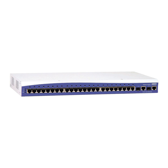
Physical Description NetVanta 1000 Series Switch Hardware Installation Guide PHYSICAL DESCRIPTION Front Panel RJ-45 Ports and LEDS The NetVanta front panels contain twenty-four 10/100BaseT Mbps Ethernet ports (RJ-45). Theses ports are consecutively numbered one through twenty-four, from left to right, with the numbers screened directly above each port. -
Page 23: Figure 3. Netvanta 1224Str Front Panel Layout
NetVanta 1000 Series Switch Hardware Installation Guide Physical Description Figure 3. NetVanta 1224STR Front Panel Layout Figure 4. NetVanta 1224R Front Panel Layout SFP Modules The NetVanta1224ST contains two SFP slots and the NetVanta 1224STR has one. All accept a number of industry-standard SFP modules. -
Page 24: Reviewing The Rear Panel Design
Physical Description NetVanta 1000 Series Switch Hardware Installation Guide Table 1. Front Panel LED Descriptions (Continued) Color Indication No DIM is installed. Green (solid) The DIM is ready. For the ISDN BRI DIM, green solid indicates that the negotiation with the switch is complete. -
Page 25: Option Modules
NetVanta 1000 Series Switch Hardware Installation Guide Option Modules OPTION MODULES The NetVanta 1224STR and NetVanta 1224R offer several option modules designed to meet a variety of networking requirements. The option modules are of two types: plug-in Network Interface Modules (NIMs) and plug-on Dial Backup Interface Modules (DIMs). -
Page 26: Network Interface Modules
Option Modules NetVanta 1000 Series Switch Hardware Installation Guide Network Interface Modules NetVanta 56K/64K NIM (P/N 1200861L1) The 56K/64K NIM (shown in Figure 7) provides a WAN interface for the NetVanta. This module provides a single 56K or 64K DDS network interface. Refer to Table A-5 on page 43 for the WAN-DDS connector pinout, and Table A-11 on page 46 for the DBU connector pinout. -
Page 27: Figure 8. Netvanta T1/Ft1 Nim
NetVanta 1000 Series Switch Hardware Installation Guide Option Modules NetVanta T1/FT1 NIM (P/N 1200862L1 and 61202862L1) The T1/FT1 NIM (shown in Figure 8) provides a T1 WAN interface for the NetVanta. This provides a full T1 or fractional T1 network interface. Refer to Table A-6 on page 43 for the WAN-T1 connector pinout, and Table A-11 on page 46 for the DBU connector pinout. -
Page 28: Figure 9. Netvanta T1/Ft1+Dsx-1 Nim
Option Modules NetVanta 1000 Series Switch Hardware Installation Guide NetVanta T1/FT1+DSX-1 NIM (P/N 1200863L1 and 61202863L1) The T1/FT1 + DSX-1 NIM (see Figure 9) provides a T1 WAN interface for the NetVanta, a full or fractional T1 network interface, and a DSX-1 interface. See the pinouts in Table A-6 on page 43 for the WAN-T1 connector, Table A-8 on page 44 for the DSX-1 connector, and Table A-11 on page 46 for the DBU connector. -
Page 29: Figure 10.Netvanta Dual T1 Nim
NetVanta 1000 Series Switch Hardware Installation Guide Option Modules NetVanta Dual T1 NIM (P/N 1200872L1) The NetVanta Dual T1 NIM (see Figure 10) provides two WAN T1 interfaces for the NetVanta. Refer to Table A-6 on page 43 for the pinouts. Refer to Table A-11 on page 46 for the DBU connector pinout. An optional DIM is required for dial backup applications. -
Page 30: Figure 11.Netvanta Serial Nim
The NetVanta Serial NIM (shown in Figure 11) is user-configurable to be either a V.35 or X.21 (V.11) interface. This module supports rates up to a maximum of 10 Mbps. An additional V.35 (ADTRAN P/N 1200873L1) or X.21 (ADTRAN P/N 1200874L1) cable is required (see Caution, below). Refer to... -
Page 31: Figure 12.Netvanta E1/Fe1 Nim
NetVanta 1000 Series Switch Hardware Installation Guide Option Modules NetVanta E1/FE1 NIM (P/N 1200868L1) The NetVanta E1 module (see Figure 12) provides a WAN/E1 interface for the NetVanta meeting the requirements of ITU-T G.703/G.704. The module provides a single 2.048 Mbps network interface. Refer to Table A-7 on page 43 for the pinouts. -
Page 32: Dial Backup Interface Modules
Option Modules NetVanta 1000 Series Switch Hardware Installation Guide Dial Backup Interface Modules NetVanta Analog Modem DIM (P/N 1200864L1) The Analog Modem DIM provides a modem with data rates up to 33.6 kbps for the NetVanta. This DIM is a plug-on card that connects to the NIM. For installation instructions, see Installing Dial Backup and Network Interface Modules on page 38. -
Page 33: Netvanta Isdn Bri Dim (P/N 1200865L1)
NetVanta 1000 Series Switch Hardware Installation Guide Option Modules NetVanta ISDN BRI DIM (P/N 1200865L1) The NetVanta ISDN BRI DIM provides dial backup access to the public switched telephone network (PSTN) via Basic Rate ISDN for the NetVanta. This DIM is a plug-on module that connects to the NIM. -
Page 34: Unit Installation
For information on configuring a specific application, refer to the quick start documents provided on your ADTRAN OS Documentation CD or the Command Line Reference Guide (also included on your CD). To prevent electrical shock, do not install equipment in a wet location or during a lightning storm. -
Page 35: Mounting Options
NetVanta 1000 Series Switch Hardware Installation Guide Unit Installation Mounting Options If you have purchased the VPN Accelerator Card, install it first (see Installing the NetVanta VPN Accelerator Card (1202368L1) on page 40). The unit may be installed in a rackmount, wallmount, or tabletop configuration. The following sections provide step-by-step instructions for rackmounting and wallmounting. - Page 36 Unit Installation NetVanta 1000 Series Switch Hardware Installation Guide Wall Mounting the NetVanta By following these instructions exactly, the NetVanta can be safely mounted to the wall. Instructions for Wall Mounting the NetVanta Step Action Remove the mounting ears. Rotate them 90 degrees so that the portion of the bracket with the mounting holes is flush with the bottom of the chassis.
-
Page 37: Supplying Power To The Unit
NetVanta 1000 Series Switch Hardware Installation Guide Unit Installation Figure 13. Repositioning the Mounting Bracket for a Wallmount Installation Supplying Power to the Unit The NetVanta comes equipped with an auto-sensing 100-250 VAC, 50/60 Hz power supply for connecting to a properly grounded power receptacle. (A detachable power cable with a grounded, three-prong plug comes with the shipment.) To power-up the unit, connect the power cable to an appropriate power source. -
Page 38: Installing Dial Backup And Network Interface Modules
Unit Installation NetVanta 1000 Series Switch Hardware Installation Guide Installing Dial Backup and Network Interface Modules The DIM plugs on to the NIM. The NIM is then installed into the rear panel option module slot. The following tables list the installation steps. Also see Figure 15 on page 39. -
Page 39: Figure 15.Nim And Dim Installation
Your NetVanta is now ready to be configured and connected to the network. For more information on configuration for a specific application, refer to the quick start documents provided on your ADTRAN OS Documentation CD. For details on the command line interface, refer to the Command Reference Guide (also included on your CD). -
Page 40: Installing The Netvanta Vpn Accelerator Card (1202368L1)
Unit Installation NetVanta 1000 Series Switch Hardware Installation Guide Installing the NetVanta VPN Accelerator Card (1202368L1) The optional VPN Accelerator Card plugs into a 32-bit PCI slot and is designed to be used in the NetVanta 1224STR to provide encryption/decryption and security acceleration services. The card provides the following security services to the host processor: DES, Triple-DES, AES, SHA-1, MD5, and Random Number Generation. -
Page 41: Appendix A. Connector Pin Definitions
Request to Send (input) Clear to Send (output) No Connect Table A-2. SFP Slots Description Description RX_LOS RGND RGND RX_DAT- RGND RX_DAT+ MOD_DEF(0) RGND MOD_DEF(1) VddR MOD_DEF(2) VddT TX_DISABLE TGND TGND TX_DAT+ TGND TX_DAT- TX_FAULT TGND 61200500L1-34C © 2004 ADTRAN, Inc. -
Page 42: Table A-3. 10/100 Baset Ports
Appendix A. Connector Pin Definitions NetVanta 1000 Series Switch Hardware Installation Guide Table A-3. 10/100 BaseT Ports Description No Connect No Connect No Connect No Connect Table A-4. 1000 BaseT Ports Description TRD0+ TRD0- TRD1+ TRD2+ TRD2- TRD1- TRD3+ TRD3- ©... -
Page 43: Table A-5. Wan-Dds Connector Pinouts
NetVanta 1000 Series Switch Hardware Installation Guide Appendix A. Connector Pin Definitions Network Interface Module Pinouts Table A-5. WAN-DDS Connector Pinouts Name Description Transmit data to the network–Ring 1 Transmit data to the network–Tip 1 — Unused Receive data from the network–Tip Receive data from the network–Ring... -
Page 44: Table A-8. Dsx-1 Connector Pinouts
Appendix A. Connector Pin Definitions NetVanta 1000 Series Switch Hardware Installation Guide Table A-8. DSX-1 Connector Pinouts Name Description Transmit data toward the DTE–Ring Transmit data toward the DTE–Tip — Unused Receive data from the DTE–Ring 1 Receive data from the DTE–Tip 1 —... -
Page 45: Table A-10. Serial Nim Connector Pinouts
NetVanta 1000 Series Switch Hardware Installation Guide Appendix A. Connector Pin Definitions Table A-10. Serial NIM Connector Pinouts Name Name TD_A TD_B ETC_A ETC_B TCLK_A TCLK_B RCLK_A RCLK_B RD_A RD_B DCD_A Unused DTR_A Unused RTS_A Unused RTS_B (V.11 only) Unused CTS_B (V.11 only) -
Page 46: Table A-11. Dbu Connector Pinouts
Appendix A. Connector Pin Definitions NetVanta 1000 Series Switch Hardware Installation Guide Dial Backup Interface Module Connectors Table A-11. DBU Connector Pinouts Name Description — Unused Network–Tip Network–Ring — Unused Table A-12. E1 DBU Connector Pinouts Name Description — Unused Network–Ring1... - Page 47 Network Interface Modules 1200861L1, 56K/64K module 26 wallmount instructions 36 1200862L1, T1/FT1 module 27 WAN LED 23 1200863L1, T1/FT1+DSX-1 module 28 warranty 11 1200866L1, Serial module 30 1200868L1, E1/FE1 module 31 1200872L1, Dual T1 module 29 61200500L1-34C © 2004 ADTRAN, Inc.
- Page 48 Index NetVanta 1000 Series Switch Hardware Installation Guide © 2004 ADTRAN, Inc. 61200500L1-34C...
Need help?
Do you have a question about the NetVanta 1000 Series and is the answer not in the manual?
Questions and answers