
Subscribe to Our Youtube Channel
Related Manuals for Midtronics DSS-5000PKIT


Summary of Contents for Midtronics DSS-5000PKIT
- Page 1 May 2017 167-000784EN-A DSS-5000 Battery Diagnostic Service System For testing 6- and 12-volt automotive / 12-volt and 24-volt charging systems. Users Guide...
-
Page 2: Table Of Contents
DSS-5000 Contents Chapter 1: Introduction Chapter 7: Messages Personal Precautions Accessing Messages Symbols Conventions Message Types Description Chapter 8: Support Accessories User Manual Tester Components Self-Diagnostics Controller Tester Pod Chapter 9: Settings Charging Dock WiFi Test Preparation Adding A Network Inspecting the Battery Deleting A Network Testing Out-of-Vehicle... -
Page 3: Chapter 1: Introduction
DSS-5000 Chapter 1: Introduction Chapter 1: Introduction Personal Precautions Symbols Conventions Symbol Description The safety symbol indicates instructions for Risk of explosive gases. avoiding hazardous conditions and personal injury. Never smoke or allow a spark or flame in the vicinity of a battery. The safety symbol with the words CAUTION, WARNING, or DANGER indicates instructions for Batteries can produce a highly explosive mix... -
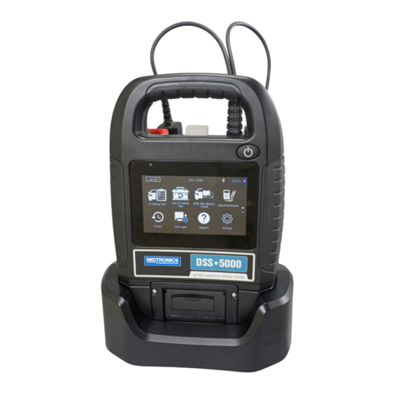
Page 4: Tester Components
Chapter 1: Introduction DSS-5000 Tester Components Tester Pod Controller Accessory Connector (Optional): For connecting an Carrying Handle: For carrying the Controller and Tester optional accessory (ex. Amp Clamp / DMM Cable) to the Pod (when attached). -
Page 5: Test Preparation
DSS-5000 Chapter 1: Introduction Test Preparation If you connect the clamps in the wrong polarity (positive to negative or negative to positive), the tester displays CLAMPS Inspecting the Battery REVERSED! Reconnect the clamps. Before starting the test visually inspect the battery for: To make sure both sides of the clamps are gripping the •... - Page 6 Select decimal point or comma and phone number. Tap Next to continue. Separator Store Name Midtronics A list of devices connected to the tester is displayed. To add a device, tap the plus (+) sign and follow the Street Address 7000 Monroe on-screen instructions.
-
Page 7: Main Menu
DSS-5000 Chapter 1: Introduction Main Menu Main Menu Icons Icon Description Log Out DSS-5000 Automates battery testing for quickly testing vehicles using the fewest steps. In Vehicle Test In Vehicle Test Out of Vehicle After New Digital Test Battery Install Multimeter For testing out-of-vehicle customer batteries for ... -
Page 8: Chapter 2: In Vehicle Test
Chapter 2: In Vehicle Test DSS-5000 Chapter 2: In Vehicle Test Manual Entry: Use the on-screen keypad to manually type Use In Vehicle Test to perform Battery Tests the 17-digit VIN and tap Next. on in-vehicle batteries using test parameters determined by vehicle VIN or year, make, and In Vehicle Test model of the vehicle being tested. -
Page 9: Battery Test Results
DSS-5000 Chapter 2: In Vehicle Test Align the temperature sensor on the Controller over the Cranking Reserve Decision Description battery and tap Capture. The test begins when the tem- Health Capacity perature is successfully captured. Good Good Battery meets or exceeds Battery Battery required standards. -
Page 10: Test Results-Summary
Chapter 2: In Vehicle Test DSS-5000 Test Results - Starter When prompted, rev the engine to between 2000 to 3000 rpm and hold it there while the analyzer tests the alterna- Decision Action tor output again. The starter voltage is normal and the battery is When prompted Idle the engine and then turn it off. - Page 11 DSS-5000 Chapter 2: In Vehicle Test Test Results - Alternator Decision Action The output from the alternator is normal. CHARGING NORMAL No output detected. Check belts to ensure alternator is rotating when engine is running. √ Check all alternator connections including NO OUTPUT to the battery.
-
Page 12: Chapter 3: Out Of Vehicle Test
Chapter 3: Out Of Vehicle Test DSS-5000 Chapter 3: Out Of Vehicle Test Align the temperature sensor on the Controller over the Use Out Of Vehicle Test to test and verify the battery and tap Capture. The test begins when the tem- condition of customer batteries that are out- perature is successfully captured. -
Page 13: Chapter 4: After New Battery Install
DSS-5000 Chapter 4: After New Battery Install Chapter 4: After New Battery Install The displayed digit counter will count up the alphanumeric Use After New Battery Install to test a newly characters as they are being entered on the keypad. installed battery in a vehicle. -
Page 14: Battery Test Results
Chapter 4: After New Battery Install DSS-5000 If the vehicle in which the new battery is being installed Test Results - Battery requires the new battery be registered to the vehicle, con- 2005 Honda Civic 1HGEM225X5Lxxxxxx 4/10/2017 2:54 PM nect the CVG module to the OBD port when prompted. -
Page 15: System Test
DSS-5000 Chapter 4: After New Battery Install Test Results-Summary Cranking Reserve Decision Description Health Capacity Test Results - Summary Badcell Replace Battery fails to meet industry > Replace Battery accepted standards. Good Battery Short Replace Charge & Replace Battery is low in charge and >... - Page 16 Chapter 4: After New Battery Install DSS-5000 Test Results - Alternator Decision Action Decision Action The starter voltage is low and the battery is discharged. Fully charge the battery and repeat the The output from the alternator is normal. starter system test. Charge Battery CHARGING...
-
Page 17: Chapter 5: Dmm
DSS-5000 Chapter 5: DMM Chapter 5: DMM Connect the clamps or probes in the correct polarity: red Use this function to troubleshoot low voltage clamp or probe to positive (+); black to negative (–). electrical circuits in a car or truck. Electrical specifications for each function are listed at the Tap AC Voltmeter. -
Page 18: Ohmmeter
Chapter 5: DMM DSS-5000 Diode Drop Tap AC Ammeter. Select the Amp Clamp range. The diode test measures the voltage drop across Follow the onscreen directions to zero the Amp Clamp. components, such as diodes. Place the clamp’s jaws around the negative (–) cable. The tester displays the measurement. -
Page 19: Temperature
DSS-5000 Chapter 5: DMM Temperature The IR temperature sensor measures the ambient surface temperature within a range of –20 to 200 °F. The tool can be used for checking the transmission for overheating, and the temperature levels of the heater and air conditioner. Temperature ... -
Page 20: Chapter 6: History
Chapter 6: History DSS-5000 Chapter 6: History Totals By Test Type Use History to access the tool usage history, a Displays test totals by test type. vehicle history based on VIN, and user histories. The search function can also be used find test History HD Battery Pack Test After New Battery Install... -
Page 21: Chapter 7: Messages
DSS-5000 Chapter 7: Messages Chapter 7: Messages The Messages function displays alerts and notifications for upcoming tests and activities. This includes scheduled testing as well as Messages tool software updates and maintenance opportunities. Mark Read Or Unread Delete Notification Perform Message Action Tap ... -
Page 22: Chapter 8: Support
Chapter 8: Support DSS-5000 Chapter 8: Support Use the Support function to access built-in Self- Testing functions or to view a digitized version of the Instruction Manual. Support User Manual Tap the icon to view the analyzer's Instruction Manual. Self-Diagnostics Use to test WiFi network and printer connections, CVG pairing, Tester Pod diagnostics, Controller display testing, and Controller touch panel testing. -
Page 23: Chapter 9: Settings
DSS-5000 Chapter 9: Settings Chapter 9: Settings Printer Settings Use the Setup options to setup and adjust WiFi, printer setup and selection, email settings, user The Printer Setup function detects and displays a information, default language, display settings, Settings list of connected and available WiFi and Bluetooth sound settings, BMIS login information, shop printers. -
Page 24: Email
Chapter 9: Settings DSS-5000 Email User Settings (Admin Only) Displays all entered email addresses. Addresses Modify Usernames and Passwords.. can be added, edited, and deleted (Admin Only). Entered email accounts are added to the email address book. Frequently used email addresses can be selected from the displayed address list rather Edit Users User Settings... -
Page 25: Display Settings
Temperature Units Default temperature units used when measuring battery temperature. Decimal Separator Default number display using commas or periods separators. Create MDCA Log File The MDCA function is used by Midtronics technical support. to return to the Shop Information screen. -
Page 26: Device List
Chapter 9: Settings DSS-5000 Date/Time Settings Device List to access the Date/Time setting defaults. Displays connected and linked accessory devices. Additional devices and CVG-2 modules can also be Select Time Format 12 Hour detected and linked to the analyzer. Select Date Format 10/18/2016 Select Time Zone Refresh... -
Page 27: Version Information
IMPORTANT: All previous modifications to the original settings will be overwritten. Legal Information Displays software attribution information via the Midtronics website. The analyzer must be connected to the Internet. Check for Updates Use this function to check via the internet connection for any... -
Page 28: Appendix A:battery Information Screen Descriptions
Appendix A:Battery Information Screen Descriptions Edit Battery Information Battery Application Vehicle Year Battery Post Vehicle Make Test Location Vehicle Model Battery Type Vehicle Technology Battery Units Battery Installation Battery Rating Back Find Battery Next A unique code, including a serial number, used by the automotive industry to identify individual motor vehicles, motorcycles, scooters and mopeds, as defined in ISO... -
Page 29: Appendix B: Recommended Test Procedure
DSS-5000 Appendix B: Recommended Test Procedure Appendix B: Recommended Test Procedure The Conductance Profiling™ technology determines battery cranking and Reserve Capacity testing. This additional process, can take up to 60 seconds to complete. IMPORTANT: Always begin each test by connecting the Tester Pod clamps to the battery being tested.
Need help?
Do you have a question about the DSS-5000PKIT and is the answer not in the manual?
Questions and answers