Midtronics DSS-5000 User Manual
Battery diagnostic
Hide thumbs
Also See for DSS-5000:
- User manual (40 pages) ,
- Instruction manual (24 pages) ,
- Quick start manual (4 pages)

Related Manuals for Midtronics DSS-5000


Summary of Contents for Midtronics DSS-5000
- Page 1 October 2017 167-000830EN-A DSS-5000 Battery Diagnostic Service System For testing 6-volt and 12-volt automotive / 12-volt and 24-volt charging systems. User Guide...
-
Page 3: Table Of Contents
DSS-5000 Contents Chapter 1: Introduction Chapter 8: Settings Personal Precautions WiFi Symbols Conventions Adding A Network Deleting A Network Description Printer Settings Accessories Adding A WiFi Printer (Admin Only) Tester Components Adding A Bluetooth Printer (Admin Only) Controller Deleting A Printer (Admin Only) -
Page 5: Chapter 1: Introduction
Keep hair, hands, and clothing as well as the analyzer cords and cables away from moving engine parts. IMPORTANT: The Subaru DSS-5000 uses a Bluetooth- Remove any jewelry or watches before you start servicing enabled Midtronics CVG module. Older CVG's shipped the battery. -
Page 6: Tester Components
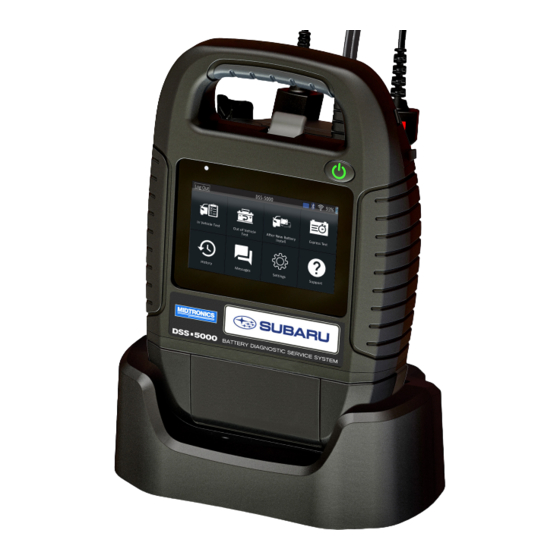
Chapter 1: Introduction DSS-5000 Tester Components Tester Pod Controller Controller Charging Contacts: For charging and communi- cating with the Controller when mounted to the Tester Pod. Carrying Handle: For carrying the Controller and Tester Pod (when attached). -
Page 7: Test Preparation
DSS-5000 Chapter 1: Introduction Test Preparation If you connect the clamps in the wrong polarity (positive to negative or negative to positive), the tester displays CLAMPS Inspecting the Battery REVERSED! Reconnect the clamps. Before starting the test visually inspect the battery for: To make sure both sides of the clamps are gripping the •... - Page 8 If the tool has already connected to "subtronics01", the Username and Password is displayed. NOTE: By default, the DSS-5000 SUB has been set If the username and password are not displayed, enter the to the U.S. Central Time Zone.
-
Page 9: Main Menu
DSS-5000 Chapter 1: Introduction Main Menu Main Menu Icons Icon Description Log Out DSS-5000 Automates battery testing for quickly testing vehicles using the fewest steps. A VIN is required and a Warranty Code is generated for all Replace In Vehicle Test Battery decisions. -
Page 10: Chapter 2: In Vehicle Test
VIN or year, make, and In Vehicle Test model of the vehicle being tested. NOTE: For an In Vehicle Test test, the DSS-5000 will al- ways associate the in-vehicle battery with the VIN of the vehicle in which it is installed. -
Page 11: Battery Test Results
DSS-5000 Chapter 2: In Vehicle Test Align the temperature sensor on the Controller over the To print or send the test results to a configured printer tap battery and tap Capture. The test begins when the tem- Send Results. To return to the Home Screen, tap Done or perature is successfully captured. -
Page 12: System Test
Chapter 2: In Vehicle Test DSS-5000 System Test Decision Action Start the engine and let it idle. The starter voltage is normal and the battery is fully charged. Tap Next. The analyzer tests the alternator output. Cranking When prompted, turn on the high beam headlights and... - Page 13 DSS-5000 Chapter 2: In Vehicle Test Decision Action The output from the alternator is normal. CHARGING NORMAL No output detected. Check belts to ensure alternator is rotating when engine is running. √ Check alternator connections to the battery. NO OUTPUT Clean or replace if necessary and retest.
-
Page 14: Chapter 3: Out Of Vehicle Test
Chapter 3: Out Of Vehicle Test DSS-5000 Chapter 3: Out Of Vehicle Test Battery Test Results Use Out Of Vehicle Test to test and verify the The test results are displayed on the Controller screen. condition of customer batteries that are out-of- vehicle for possible return and/or warranty claim. -
Page 15: Chapter 4: After New Battery Install
(Red positive [+], Black to negative [–]). Remove the Controller from the Tester Pod. IMPORTANT: The Subaru DSS-5000 uses a Blue- tooth-enabled Midtronics CVG module. Older On the Controller at the Main Menu tap After New Battery CVG's shipped with Subaru GR8 Diagnostic Char- Install. -
Page 16: Battery Test Results
Chapter 4: After New Battery Install DSS-5000 Battery Test Results The Edit Battery Information screen displays vehicle and battery information based on the VIN. Test Results - Battery If the displayed information is correct, tap Next to begin 2015 Subaru Legacy JF1VA1L66H9xxxxxx 8/29/2017 9:54 AM the Battery Test. -
Page 17: System Test
DSS-5000 Chapter 4: After New Battery Install A Test Results - Summary screen is displayed following a Cranking Reserve > Decision Description System Test. Tap to view detail test results for each part of Health Capacity the test. Charge &... - Page 18 Chapter 4: After New Battery Install DSS-5000 Alternator Test Results Test Results - Diode Decision Action Test Results - Alternator 2015 Subaru Legacy JF1VA1L66H9xxxxxx 8/29/2017 9:54 AM One or more diodes in the alternator are not functioning or there is stator damage, which is No Load Voltage: 14.45 V...
-
Page 19: Chapter 4: Express Test
DSS-5000 Chapter 4: Express Test Chapter 4: Express Test Manual Entry: Use the on-screen keypad to manually type Use the Express Test for vehicles in for Quick the 17-digit VIN and tap Next. Lane service. A VIN is required for a Warranty Code to be created. - Page 20 Chapter 4: Express Test DSS-5000 Align the temperature sensor on the Controller over the battery and tap Capture. The test begins when the tem- perature is successfully captured. Temperature 1. Align battery in viewing window with target centered on battery housing.
-
Page 21: Chapter 6: History
DSS-5000 Chapter 6: History Chapter 6: History Totals By Date And Location Use History to access the tool usage history, a Displays test totals by time interval. Also displays the number vehicle history based on VIN, and user histories. of tests performed in and out of vehicle. -
Page 22: Chapter 7: Messages
Chapter 7: Messages DSS-5000 Chapter 7: Messages to read a message. The Messages function displays alerts and notifications for upcoming tests and activities. to perform the message action item. This includes scheduled testing as well as Messages tool software updates and maintenance to delete a message. -
Page 23: Chapter 8: Settings
BMIS login information, shop printers. information, user management, connected accessories, and device information. IMPORTANT: The DSS-5000 can only connect to Tap to return to the previous screen or to return to the printers on the same wireless WiFi network. This in- Main Menu. -
Page 24: Email
Chapter 8: Settings DSS-5000 Email User Settings Displays all entered email addresses. Addresses Tap the to turn on or off the Enable User Accounts can be added, edited, and deleted (Admin Only). option. When Enable User Accounts is on, the Entered email accounts are added to the email available user list is displayed on the start-up screen. -
Page 25: Display Settings
Dealers Create MDCA Log File The Location Selection screen (Admin Only) is displayed. Scroll The MDCA function is used by Midtronics technical support. to find the correct location or tap to search for a specfic location. Tap Next to continue. -
Page 26: Device List
Tap Yes to delete. 2015 Add CVG Device 2016 IMPORTANT: The Subaru DSS-5000 uses a Bluetooth- 2017 enabled Midtronics CVG module. Older CVG's shipped with Subaru GR8 Diagnostic Chargers are WiFi-enabled and not compatible with the DSS-5000. -
Page 27: Factory Preset
IMPORTANT: All previous modifications to the original settings will be overwritten. Legal Information Displays software attribution information via the Midtronics website. The analyzer must be connected to the Internet. Check for Updates BMIS status is displayed when tester is powered up. Check for tester software updates via the connected WiFi network. -
Page 28: Chapter 9: Support
Chapter 9: Support DSS-5000 Chapter 9: Support Use the Support function to access built-in Self- Testing functions or to view a digitized version of the Instruction Manual. Support User Manual Tap the icon to view the analyzer's Instruction Manual. Self-Diagnostics... -
Page 29: Appendix A: Battery Information Screen Descriptions
Appendix A: Battery Information Screen Descriptions Edit Battery Information Battery Application Vehicle Year Battery Post Vehicle Make Test Location Vehicle Model Battery Type Vehicle Technology Battery Units Battery Installation Battery Rating Back Find Battery Next A unique code, including a serial number, used by the automotive industry to identify individual motor vehicles, motorcycles, scooters and mopeds, as defined in ISO... -
Page 30: Appendix B: Recommended Test Procedure
VIN Scanning The DSS-5000 uses a camera built into the Controller handle to scan the VIN of the vehicle being tested. This number is then cross referenced with the original equipment manufacturer's battery specifications stored in the tester's database and displayed on the Controller screen. - Page 31 DSS-5000 Appendix B: Recommended Test Procedure www.midtronics.com Midtronics Inc. 7000 Monroe Street Willowbrook, IL 60527...
- Page 32 PATENTS This product is made by Midtronics, Inc., and is protected by one or more U.S. and foreign patents. For speci c patent information, contact Midtronics, Inc. at +1 630 323-2800. LIMITED WARRANTY Midtronics products are warranted to be free of defects in materials and workmanship for a period of one (1) year from date of purchase.
Need help?
Do you have a question about the DSS-5000 and is the answer not in the manual?
Questions and answers