
Related Manuals for Omron FH-SMDA-GS050B


Summary of Contents for Omron FH-SMDA-GS050B
- Page 1 Vision Sensor FH Series Vision System Hardware Setup Manual for 3D Robot Vision FH-505£ FH-SMDA-GS050B Z436-E1-05...
- Page 2 No patent liability is assumed with respect to the use of the information contained herein. Moreover, because OMRON is constantly striving to improve its high-quality products, the information con- tained in this manual is subject to change without notice. Every precaution has been taken in the preparation of this manual.
-
Page 3: Intended Audience
• Personnel in charge of managing FA systems and facilities. Applicable Products This manual covers the following products. • FH-505£, FH-SMDA-GS050B FH-505£-10, FH-505£-20, FH-555£, FH-555£-10, and FH-555£-20 are not applicable. Part of the specifications and restrictions are given in other manuals. Refer to Relevant Manuals on Related Manuals on page 29. -
Page 4: Manual Structure
Manual Structure Manual Structure Page Structure The following page structure is used in this manual. Level 1 heading 4 Installation and Wiring Level 2 heading Level 3 heading Mounting Units Level 2 heading Gives the current Level 3 heading headings. 4-3-1 Connecting Controller Components The Units that make up an NJ-series Controller can be connected simply by pressing the Units together... -
Page 5: Special Information
Manual Structure Special Information Special information in this manual is classified as follows: Precautions for Safe Use Precautions on what to do and what not to do to ensure safe usage of the product. Precautions for Correct Use Precautions on what to do and what not to do to ensure proper operation and performance. Additional Information Additional information to read as required. - Page 6 Manual Structure FH Series Vision System Hardware Setup Manual for 3D Robot Vision (Z436-E1)
-
Page 7: Sections In This Manual
Sections in This Manual Sections in This Manual Confirm the Package Overview of FH series Configuration Handling and Installation Environment Setup and Wiring I/O Interface Index FH Series Vision System Hardware Setup Manual for 3D Robot Vision (Z436-E1) -
Page 8: Table Of Contents
Optical axis (FH-SMDA-GS050B)........................24 Image Sensor (FH-SMDA-GS050B)......................24 Failsafe Measures (FH-SMDA-GS050B).......................24 Warm-up (FH-SMDA-GS050B)........................25 Camera Installation (FH-SMDA-GS050B) .....................25 Connection and Operation with the Robot (FH-SMDA-GS050B) ..............25 LED Safety (FH-SMDA-GS050B) ........................25 Camera Calibration Target (FH-XCAL-S) ......................25 HandEye Calibration Target (FH-XCAL-R) ....................25 Regulations and Standards .................. 27 FH-505£................................27... - Page 9 CONTENTS FH-SMDA-GS050B............................28 Related Manuals..................... 29 Revision History..................... 31 Section 1 Confirm the Package Sensor Controller........................1-2 1-1-1 FH-505£ .............................1-2 3D Cameras and Related.......................1-3 1-2-1 Camera ............................1-3 1-2-2 Camera Cable ..........................1-3 1-2-3 Camera I/O Cable ........................1-3 FH Application Software .......................1-4 Calibration Target ........................1-5 Sold Separately ........................1-6...
- Page 10 CONTENTS Sensor Controller Installation....................5-5 5-3-1 FH-505£ .............................5-5 Setup Touch Panel Monitor or Monitor................5-10 5-4-1 FH-505£ ...........................5-10 Camera Installation......................5-11 5-5-1 FH-505£ ........................... 5-11 5-5-2 Installation of 3D Vision Sensor ....................5-12 Insert/Remove SD Memory Card or USB Flash Drive............5-16 5-6-1 FH-505£ ...........................5-16 Use by Connecting Software ....................5-17 5-7-1 Simulation Software ........................5-17...
-
Page 11: Terms And Conditions Agreement
Omron’s exclusive warranty is that the Products will be free from defects in materials and work- manship for a period of twelve months from the date of sale by Omron (or such other period ex- pressed in writing by Omron). Omron disclaims all other warranties, express or implied. -
Page 12: Application Considerations
WAY CONNECTED WITH THE PRODUCTS, WHETHER SUCH CLAIM IS BASED IN CONTRACT, WARRANTY, NEGLIGENCE OR STRICT LIABILITY. Further, in no event shall liability of Omron Companies exceed the individual price of the Product on which liability is asserted. Application Considerations... - Page 13 Product. Errors and Omissions Information presented by Omron Companies has been checked and is believed to be accurate; how- ever, no responsibility is assumed for clerical, typographical or proofreading errors or omissions. FH Series Vision System Hardware Setup Manual for 3D Robot Vision (Z436-E1)
-
Page 14: Safety Precautions
Safety Precautions Safety Precautions Symbols and the Meanings for Safety Precautions Described in This Manual The following notation is used in this manual to provide precautions required to ensure safe usage of a Sensor Controller. The safety precautions that are provided are extremely important to safety. Always read and heed the information provided in all safety precautions. -
Page 15: Warning
Safety Precautions Warning WARNING This product must be used according to this manual and Instruction Sheet. Failure to ob- serve this may result in the impairment of functions and performance of the product. This product is not designed or rated for ensuring the safety of persons. Do not use it for such purposes. - Page 16 Safety Precautions FH series does not comply with the laws and regulations for industrial robot safety. When us- ing the FH series in a robot system that includes an industrial robot, be sure to check for compliance with laws and regulations regarding the safety of industrial robots. Take steps to ensure safety as needed.
- Page 17 Safety Precautions If the 3D Vision Sensor shape is not registered, the 3D Vision Sensor may collide with the container and be damaged. Please register the 3D Vision Sensor shape when you register the hand data. Do not perform camera calibration during the warm-up operation of the 3D Vision Sensor. Measurement errors occur when the geometric positional relationship between the lighting section and imaging section of the 3D Vision Sensor changes due to factors such as aging, temperature changes, or impact on the 3D Vision Sensor.
- Page 18 Safety Precautions When using a device equipped with the USB flash drive or SD Memory Card function, there is a security risk that a third party may acquire, alter, or replace the files and data in the re- movable media by removing the removable media or unmounting the removable media. Please take sufficient measures, such as restricting physical access to the Controller or tak- ing appropriate management measures for removable media, by means of locking the instal- lation area, entrance management, etc., by yourself.
-
Page 19: Precautions For Safe Use
Applications under conditions and environment not described in specifications. 1. In addition to the applications listed from (a) to (d) above, Omron products (see definition) are not intended for use in vehicles designed human transport (including two wheel vehicles). Please do NOT use Omron products for vehicles designed human transport. -
Page 20: Grounding (Fh-505£)
Precautions for Safe Use • The recommended power supply is the S8VS-£££24 (manufactured by OMRON) or S8VK-G-££ £24 (manufactured by OMRON). • Select and use the appropriate wire size (AWG16 to 10) based on consumption current. • Keep the power supply wires as short as possible (Max 2m). -
Page 21: Others (Fh-505£)
• Avoid installing the product in places with vibration as much as possible. Power Supply and Wiring (FH-SMDA-GS050B) • Make sure to use the product with the power supply voltage specified. If a DC voltage exceeding the rating or an AC voltage is applied, the circuit parts may be burnt or exploded. -
Page 22: Mounting (Fh-Smda-Gs050B)
Otherwise, the product may malfunction or be broken. • If anything abnormal occurs, for example, strange smell/sound is detected, the main unit gets very hot, or a smoke comes, stop using the product, turn OFF the product, and consult OMRON’s branch or sales office. -
Page 23: Camera Calibration Target (Fh-Xcal-S)
Precautions for Safe Use • Do not drop the product or expose it to abnormal vibration or impact. Doing so may lead to product failure. • When operating the robot by using the vision sensor measurement results, be sure to check the measurement result data on the robot side and take fail-safe measures, such as operating the robot only after confirming that the data is within the robot's range of motion. -
Page 24: Precautions For Correct Use
Precautions for Correct Use Precautions for Correct Use Please observe the following precautions to prevent failure to operate, malfunction, or undesirable ef- fect. Installation and Storage Sites (FH-505£) Install and store the product in a location that meets the following conditions: •... -
Page 25: Maintenance (Fh-505£)
If such re-recognition processing happens at switching opera- tion, it may cause measurement time to be longer. Installation Location (FH-SMDA-GS050B) In order to prevent the product from becoming inoperable or malfunction, and to prevent other adverse effects to the performance or equipment, please observe the following. -
Page 26: Power Supply, Connection, And Wiring (Fh-Smda-Gs050B)
Precautions for Correct Use Power Supply, Connection, and Wiring (FH-SMDA-GS050B) • If using a commercially available switching regulator, earth the frame ground terminal. • If the power supply line has surge, connect a surge absorber according to the operational environ- ment to use the product. -
Page 27: Warm-Up (Fh-Smda-Gs050B)
• In an environment exposed to high humidity and sharp temperature fluctuation, the window may be- come cloudy in rare cases. Connection and Operation with the Robot (FH-SMDA-GS050B) • For an example design of a robot program to build an application, see the sample program (fhsam- ple_main()) of the Robot Connection Guide. - Page 28 Precautions for Correct Use • When disposing of this product, treat it as industrial waste and never heat or incinerate it at 100 °C or higher. FH Series Vision System Hardware Setup Manual for 3D Robot Vision (Z436-E1)
-
Page 29: Regulations And Standards
Regulations and Standards Regulations and Standards FH-505£ Using Product Outside Japan If you export (or provide a non-resident with) this product or a part of this product that falls under the category of goods (or technologies) specified by the Foreign Exchange and Foreign Trade Control Law as those which require permission or approval for export, you must obtain permission or approval or service transaction permission) pursuant to the law. -
Page 30: Fh-Smda-Gs050B
• EMC-related performance of the OMRON devices will vary depending on the configuration, wiring, and other conditions of the equipment or control panel on which the OMRON devices are installed. • The customer must, therefore, perform the final check to confirm that devices and the overall ma- chine conform to EMC standards. -
Page 31: Related Manuals
FH FH-5£££-££ System FH series series in the manual. Sensor Controller. 3D Vision Sensor 3290410-0 FH-SMDA-GS050B To confirm the safety Describes the definitions of basic FH-SMDA Instruction and usage precau- terms, the meaning of signal words, Sheet... - Page 32 Related Manuals Name of Manual Cat. No. Model Purpose Contents Vision System Z365 FH-2£££ When User want to Describes the soft functions, setup, FH/FHV Series FH-2£££-££ know about the and operations to use FH/FHV ser- User's Manual FH-5£££ FH/FHV series. ies.
-
Page 33: Revision History
Revision History Revision History A manual revision code appears as a suffix to the catalog number on the front and back covers of the manual. Cat. No. Z436-E1-05 Revision code Rev. Code Rev. Date Revision Contents Feb. 2021 Original product Sep. - Page 34 Revision History FH Series Vision System Hardware Setup Manual for 3D Robot Vision (Z436-E1)
- Page 35 Confirm the Package Sensor Controller ................... 1-2 1-1-1 FH-505£......................1-2 3D Cameras and Related ................1-3 1-2-1 Camera ......................1-3 1-2-2 Camera Cable....................1-3 1-2-3 Camera I/O Cable................... 1-3 FH Application Software................1-4 Calibration Target................... 1-5 Sold Separately ....................1-6 1-5-1 Monitor......................
-
Page 36: Sensor Controller
1 Confirm the Package Sensor Controller First, please check to see whether the package has all the necessary Sensor Controller parts. 1-1-1 FH-505£ • Sensor Controller: 1 FH-505£: 1 • Instruction sheet: 1 • Instruction Installation Manual for FH series: 1 •... -
Page 37: Cameras And Related
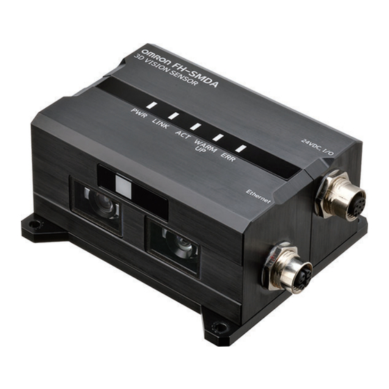
1 Confirm the Package 3D Cameras and Related 1-2-1 Camera Appear- Type Field of vision Imaging area Model ance 3D vision sensor 400 x 300 mm 400 to 600 mm FH-SMDA- GS050B 1-2-2 Camera Cable Appear- Description Model ance Ethernet cable super bending resistance straight FHV-VNBX2 Cable length: 5 m, 10 m £M... -
Page 38: Fh Application Software
1 Confirm the Package FH Application Software Appear- Description Model ance FH-UM3D1 3D Robot Vison Software Installer This product can be installed on the FH-505£ (version 6.40 or later). FH Series Vision System Hardware Setup Manual for 3D Robot Vision (Z436-E1) -
Page 39: Calibration Target
1 Confirm the Package Calibration Target Appear- Description Model ance Handeye Calibration Target FH-XCAL-R Camera Calibration Target FH-XCAL-S FH Series Vision System Hardware Setup Manual for 3D Robot Vision (Z436-E1) -
Page 40: Sold Separately
1 Confirm the Package Sold Separately 1-5-1 Monitor Monitor Appear- Description Model ance FH-MT12 Touch Panel Monitor 12.1 inches (for FH Sensor Controllers) LCD Monitor 8.4 inches FZ-M08 FH Series Sensor Controllers version 5.32 or higher is required. Monitor Cables Appear- Description Model... -
Page 41: Lighting And Lighting Controller
1 Confirm the Package 1-5-2 Lighting and Lighting Controller Appear- Description Model ance External Lighting FLV Series FL Series Lighting Control- For FLV-Series Analog Lighting Controller FLV-ATC Series ler (Required to control external lighting from a Controller) For the method of setting the lighting controller, please refer to the respective instruction manual. 1-5-3 Accessories Appear-... -
Page 42: Cable
Recom- Cable Appear- mended lengt Item Model ance manufac- turer Cable with Connectors on Both Ends OMRON XS6W-6PUR8SS30CM-YF (RJ45/RJ45) XS6W-6PUR8SS50CM-YF tandard RJ45 plugs type XS6W-6PUR8SS100CM-YF Wire Gauge and Number of Pairs: XS6W-6PUR8SS200CM-YF AWG26, 4-pair Cable XS6W-6PUR8SS300CM-YF Cable Sheath material: PUR... - Page 43 Cables with rugged RJ45 plugs are available in the following lengths: 0.3 m, 0.5 m, 1 m, 2 m, 3 m, 5 m, 10 m, 15 m. For details, refer to the Industrial Ethernet Connectors Catalog (Cat. No. G019). Cables colors are available in yellow, green, and blue. For details, contact your OMRON representative. Cables / Connectors Recommended Item...
- Page 44 1 Confirm the Package 1-10 FH Series Vision System Hardware Setup Manual for 3D Robot Vision (Z436-E1)
-
Page 45: Overview Of Fh Series
Overview of FH series Basic System of Measurement ..............2-2 2-1-1 System Configuration ..................2-4 Flow of Use Procedure .................. 2-5 FH Series Vision System Hardware Setup Manual for 3D Robot Vision (Z436-E1) -
Page 46: Basic System Of Measurement
2 Overview of FH series Basic System of Measurement An FH series Sensor Controller uses pre-built packages that contain all the processing tasks (for im- age input, measurement processing, displays, outputs, etc.) that are required for vision inspections. You arrange these packaged processes in order of execution of the vision inspection. An FH series Sensor Controller executes vision inspections according to user-created flows. - Page 47 2 Overview of FH series Concept of Measurement Processing When the FH receives a measurement trigger from the PLC or other external device, the image input from a Camera, measurement processing, and output of measurement results (e.g., OK/NG judge- ment results) are executed in the order that those processing items are registered in the measurement flow.
-
Page 48: System Configuration
In case of switching multiple of sensor controllers with a single monitor or touch panel monitor, Monitor cable please make sure to use an appropriate product. Recommended model by OMRON: FZ-DU FH-VMDA (2 m, 5 m, 10 m, min. bending radius 36 mm) -
Page 49: Flow Of Use Procedure
2 Overview of FH series Flow of Use Procedure The following table shows the flow for using the FH. Procedure Description Reference Preparations Installation and Wiring Section 4 Handling and Installation Envi- ronment on page 4-1 Section 5 Setup and Wiring on page ↓... - Page 50 2 Overview of FH series Procedure Description Reference Scene Editing In the Main Window (layout 0), edit the Vision System FH series 3D Robot Vision measurement flow. Application Construction Guide (Cat.No. • Register processing items. Z446) and Vision System FH/FHV series •...
-
Page 51: Configuration
Configuration Sensor Controller ................... 3-2 3-1-1 FH-505£......................3-2 Camera and Cables ..................3-9 3-2-1 3D Vision Sensor .................... 3-9 3-2-2 Camera Cable....................3-13 3-2-3 Camera I/O Cable..................3-17 Calibration Target..................3-19 Touch Panel Monitor and Cable..............3-21 LCD and Cable....................3-27 FH Series Vision System Hardware Setup Manual for 3D Robot Vision (Z436-E1) -
Page 52: Sensor Controller
Parallel Processing Number of Connectable Camera 1 (Connect to the Ethernet port.) Supported Camera FH-SMDA-GS050B Possible Number of Logging Im- Both 3D and 2D imaging: Up to 14 images ages to Sensor Controller 3D imaging only, 2D imaging only: Up to 29 images... - Page 53 3 Configuration Series FH-5000 Series Type High-speed, Large-capacity Controller(4 cores) Model FH-5052/FH-5051/FH-5050 Encoder Interface Not supported. Monitor Interface DVI-I output (Analog RGB & DVI-D single link) x 1 USB I/F USB2.0 host x 2 (BUS Power: 5 V/0.5 A per port) USB3.0 host x 2 (BUS Power: 5 V/0.9 A per port) SD Card I/F SDHC x 1...
- Page 54 3 Configuration Series FH-5000 Series Type High-speed, Large-capacity Controller(4 cores) Model FH-5052/FH-5051/FH-5050 External Fea- Dimensions 190 mm x 115 mm x 182.5 mm tures Note Height: Including the rubber at the base. Weight Approx.3.4kg Degree of protection IEC60529 IP20 Case material Cover: zinc-plated steel plate, Side plate: aluminum (A6063) Existing the third class grounding...
- Page 55 3 Configuration Component Names and Functions Connector name Description SD memory card Install the SD memory card. Do not plug or unplug the SD memory card during installation con- measurement operation. Otherwise measurement time may be affected or data nector may be destroyed.
- Page 56 3 Configuration Connector name Description EtherCAT commu- Connect the opposed EtherCAT device. nication connector (IN) EtherCAT commu- Connect the opposed EtherCAT device. nication connector (OUT) Encoder connec- Not supported. Camera connec- Not supported. Do not connect cameras. Power supply ter- Connect a DC power supply.
- Page 57 3 Configuration LED name Description Ethernet NET Lit while Ethernet communications are usable. RUN1 LED Ethernet LINK/ Lit when connected with an Ethernet device, and blinks while performing com- ACT1 LED munications. Ethernet NET Lit while Ethernet communications are usable. RUN2 LED Ethernet LINK/ Lit when connected with an Ethernet device, and blinks while performing com-...
- Page 58 4.5 mm (Unit: mm) 26.7 148.5 Additional Information We have the 2D CAD data or 3D CAD data. You can download CAD data from www.fa.omron.co.jp. FH Series Vision System Hardware Setup Manual for 3D Robot Vision (Z436-E1)
-
Page 59: Camera And Cables
3 Configuration Camera and Cables 3-2-1 3D Vision Sensor Specification Model FH-SMDA-GS050B Image elements CMOS image elements Color/Monochrome Monochrome Effective pixels 1296(H) x 972(V) Shutter function Electronic shutter, Shutter speeds can be set from 1 ms to 50 ms. Measurement range... - Page 60 3 Configuration Precautions for Correct Use • This camera cannot be used as a measuring instrument, because it is not an absolute dis- tance. Use in combination with robot calibration. • If there are slight unevennesses, it cannot be recognized. There must consist of a surface of 20 x 20 mm or more •...
- Page 61 3 Configuration Dimensions dia. Mounting screw holes Optical Axis Optical Axis (Unit: mm) 3-11 FH Series Vision System Hardware Setup Manual for 3D Robot Vision (Z436-E1)
- Page 62 3 Configuration Measurement Range and Field of View ●Measurement range ●Measurement position Measurement position Measurement position Z: 15 mm 400 mm Front Measurement position Y: 25 mm Z: 200 mm Y: 300 mm X: 35 mm X: 400 mm Measurement range (X,Y,Z) 400x300x200 mm 400 mm 3-12 FH Series Vision System Hardware Setup Manual for 3D Robot Vision (Z436-E1)
-
Page 63: Camera Cable
3 Configuration 3-2-2 Camera Cable Specification • Camera cable (Ethernet, straight) Item FHV-VNBX2 5M FHV-VNBX2 10M Cable length 10 m Cable type Bending resistance cable Connector type Straight connector Outer diameter 6.6 + 0.7 mm dia. Min. bending radius 40 mm Usage environ- Ambient temper- Operating: -10 to +70°C, Storage: -25 to +85°C (with no icing or conden-... - Page 64 3 Configuration • Camera cable (Ethernet, right angle) Item FHV-VNLBX2 5M FHV-VNLBX2 10M Cable length 10 m Cable type Bending resistance cable Connector type Right angle connector Outer diameter 6.6 + 0.7 mm dia. Min. bending radius 40 mm Usage environ- Ambient temper- Operating: -10 to +70°C, Storage: -25 to +85°C (with no icing or conden- ment...
- Page 65 3 Configuration Dimensions • Ethernet cable (straight) FHV-VNBX2 (Unit: mm) *1. Cable lengths (L) are 5 m/10 m. FHV-VNBX 58.3 53.5 (Unit: mm) *1. Cable lengths (L) are 3 m/5 m/10 m. 3-15 FH Series Vision System Hardware Setup Manual for 3D Robot Vision (Z436-E1)
- Page 66 *1. Cable lengths (L) are 3 m/5 m/10 m. Additional Information We have the 2D CAD data or 3D CAD data. You can download CAD data from www.fa.omron.co.jp. 3-16 FH Series Vision System Hardware Setup Manual for 3D Robot Vision (Z436-E1)
-
Page 67: Camera I/O Cable
3 Configuration 3-2-3 Camera I/O Cable Specification • Camera I/O cable (straight) Item FH-VSDX-BX 3M FH-VSDX-BX 5M FH-VSDX-BX 10M Cable length 10 m Cable type Bending resistance cable Connector type Straight connector Size AWG26 Outer diameter 5.8 mm dia. Min. bending radius 35 mm Usage environ- Ambient temper-... - Page 68 *1. Cable lengths (L) are 3 m/5 m/10 m. Additional Information We have the 2D CAD data or 3D CAD data. You can download CAD data from www.fa.omron.co.jp. 3-18 FH Series Vision System Hardware Setup Manual for 3D Robot Vision (Z436-E1)
-
Page 69: Calibration Target
3 Configuration Calibration Target Specification Model FH-XCAL-R FH-XCAL-S Name HandEye calibration target Camera calibration target Ambient tempera- -25 to +65°C (with no icing or condensation) ture range Ambient humidity 35 to 85% (with no condensation) range Ambient atmos- No corrosive gases phere Vibration tolerance Oscillation frequency: 10 to 150 Hz, Half amplitude: 0.35 mm, Sweep time: 8 minute/... - Page 70 Handle (X2) Mounting screw holes (Unit: mm) Additional Information We have the 2D CAD data or 3D CAD data. You can download CAD data from www.fa.omron.co.jp. 3-20 FH Series Vision System Hardware Setup Manual for 3D Robot Vision (Z436-E1)
-
Page 71: Touch Panel Monitor And Cable
3 Configuration Touch Panel Monitor and Cable Touch Panel Monitor of FH-MT12 is connectable with FH Sensor Controller whose software is Ver. 5.32 or later. For connection of Touch Panel Monitor and FH Sensor Controller, the monitor cable for video and touch panel cable are necessary. - Page 72 3 Configuration Component Names and Functions ●Front view ●Rear view (2) VESA mounting hole pitch 75 mm (M4) (1) LED indicator lamp (3) VESA mounting hole pitch 100 mm (M4) (5) Power supply terminal (4) USB retaining bracket ●Connection terminal (7) OSD Menu button (8) RS-232C (6) Monitor connector...
- Page 73 3 Configuration Touch Panel Monitor Cable Normally, use the USB cable as a connection cable for Touch Panel Monitor. Use the RS-232C cable as a connection cable for Touch Panel Monitor in the following cases. • When Touch Panel Monitor is taken apart 5 m or more from FH Sensor Controller. •...
- Page 74 The power terminal block for the Touch Panel Monitor is located on the back of it. Connect a power supply of 24 VDC there. 24 VDC Recommended model Power supply by OMRON: 24 VDC S8VS-03024 Indication on the power terminal...
- Page 75 3 Configuration - Recommended wire size: AWG 13 to 22 (0.326 to 2.62 mm - Terminal screw: M4 (Tightening torque: 1.0 N•m) - Crimping Terminal 8.0 mm max. 8.0 mm max. Dimensions Touch Panel Monitor 8-M4 EFFECTIVE SCREW LENGTH6 MOUNTING PLATE THICKNESS 1.6-4.8 37.5...
- Page 76 3 Configuration *1. Cable is available in 2 m/5 m/10 m. (Unit: mm) USB Cable for Touch Panel Monitor: FH-VUAB 45±5 12±0.25 10±2 45±5 12±0.25 8 max. 4-pin USB B type connector 10.5 max. 4-pin USB A type connector *1.
-
Page 77: Lcd And Cable
3 Configuration LCD and Cable Specification LCD Monitor Model FZ-M08 Size 8.4 inches Type Liquid crystal color TFT Resolution 1,024 x 768 dots Input signal Analog RGB video input 1 channel Supply Voltage 21.6 to 26.4 VDC Current consumption Approx. - Page 78 Connect a power supply of 24 VDC there. 24 VDC (Outside diameter of crimp terminal: Dia 5.5 mm maximum) Recommended model Power OMRON Corporation-manufactured supply 24 VDC S8VS-03024 • Keep the power supply wires as short as possible (maximum 10 m). 3-28...
- Page 79 3 Configuration • If UL recognition is required, use a UL class II power supply. Regarding installation, do not use the VESA mounting but fix the monitor unit using the board mount- ing. Dimensions LCD Monitor: FZ-M08 Mountable board thickness: 1.6 to 4.8 (103.5) (31.5) 4-M4...
- Page 80 3 Configuration 3-30 FH Series Vision System Hardware Setup Manual for 3D Robot Vision (Z436-E1)
-
Page 81: Handling And Installation Environment
Handling and Installation Environ- ment FH-505£ ......................4-2 FH Series Vision System Hardware Setup Manual for 3D Robot Vision (Z436-E1) - Page 82 4 Handling and Installation Environment FH-505£ WARNING This product must be used according to this manual and Instruction Sheet. Failure to ob- serve this may result in the impairment of functions and performance of the product. This product is not designed or rated for ensuring the safety of persons. Do not use it for such purposes.
- Page 83 4 Handling and Installation Environment Precautions for Correct Use Installation and Storage Sites Install and store the product in a location that meets the following conditions: • Surrounding temperature of 0 to +45°C (-20 to +65°C in storage) Do not let the ambient temperature exceed 45°C (117°F). Provide a forced-air fan cooling or air conditioning if the ambient temperature is near 45°C (117°F) so that the ambient temperature never exceeds 45°C (117°...
- Page 84 4 Handling and Installation Environment • For good ventilation, provide a clearance of 50 [mm] or more above the Sensor Controller away from other devices in the normal floor mounting. For the right and left sides, provide a clearance of 30 [mm] or more, and for the back side, 15 [mm] or more. These clearances are also required when mounting multiple Sensor Controllers side by side.
-
Page 85: Setup And Wiring
Setup and Wiring When turning ON and OFF ................5-2 5-1-1 FH-505£......................5-2 Fail-Safe Measures..................5-4 Sensor Controller Installation ............... 5-5 5-3-1 FH-505£......................5-5 Setup Touch Panel Monitor or Monitor ............5-10 5-4-1 FH-505£....................... 5-10 Camera Installation ..................5-11 5-5-1 FH-505£......................5-11 5-5-2 Installation of 3D Vision Sensor .............. -
Page 86: When Turning On And Off
• After confirming that the product is started up, communicate with the high-order device. • Should you notice any abnormalities, immediately stop use, turn OFF the power supply, and contact your OMRON representative. FH Series Vision System Hardware Setup Manual for 3D Robot Vision (Z436-E1) - Page 87 5 Setup and Wiring Precautions for Correct Use Turning OFF the Power When a message is displayed indicating that a task is in progress, do not turn OFF the power. Doing so causes the data in the memory to be corrupted, resulting in the product not operating properly upon the next start-up.
-
Page 88: Fail-Safe Measures
5 Setup and Wiring Fail-Safe Measures The fail-safe measures are the same for each series. Confirm the following instructions. WARNING Please take external safety measures so that the system as a whole should be on the safe side even if a failure of a Sensor Controller, a failure of a 3D Vision Sensor, or an error due to an external factor occurred. -
Page 89: Sensor Controller Installation
5 Setup and Wiring Sensor Controller Installation 5-3-1 FH-505£ Precautions for Safe Use Power Supply and Wiring • Make sure to use the product with the power supply voltage specified by this manual. • Provide the power from a DC power supply (safety extra-low voltage circuits) that has been taken measures not to generate high-voltage. - Page 90 5 Setup and Wiring Use the specified wire size (AWG10 to 16) and keep the power supply wires as short as possible (Max. 2 m). Insert the end of the signal line (electric wire) into the terminal block connector (male), and tighten the three screws on the connector top to fix the wire.
- Page 91 5 Setup and Wiring Sensor Controller Sensor Controller Sensor Controller Other Other Other device device device Ground of 100 Ω or less (a) Independent grounds: (b) Common ground: (c) Common ground: Best Acceptable Incorrect Grounding Methods Insert the terminal block connector (male) to the terminal block connector (female) of Sensor Controller.
- Page 92 5 Setup and Wiring When you connect your camera to the lighting via Light Controller, the current consumption is same as when the Intelligent Compact Digital camera is connected. Connected camera, Lighting controller, and Item FH-505£ Lighting type • Recommended Power S8VK-G24024 When connecting intelligent compact digital Source...
- Page 93 5 Setup and Wiring Side Mounting (Unit: mm) • Left side • Right side 4-M4 depth 4.5 (mounting screw hole) 4-M4 depth 4.5 (mounting screw hole) 19.2 19.5 182.5 20.1 * Recommended tightening torque: 1.2 N•m to 1.3 N•m * The tolerance is ±0.2 mm.
-
Page 94: Setup Touch Panel Monitor Or Monitor
5 Setup and Wiring Setup Touch Panel Monitor or Moni- Describes the notifications of Sensor Controller when you setup Touch Panel Monitor or Monitor. For handling or functions of monitor, refer to each of instruction sheet. 5-4-1 FH-505£ Precautions for Safe Use •... -
Page 95: Camera Installation
5 Setup and Wiring Camera Installation Guidelines and precautions for Sensor Controller installation when cameras are also installed. For handling and function information for specific cameras, refer to the appropriate instruction sheet. 5-5-1 FH-505£ WARNING If you keep watching the LED light, it may have an adverse effect on the eyes, do not stare directly into the light emitted from the LED. -
Page 96: Installation Of 3D Vision Sensor
Attach the camera to the 6th axis of the 6-axis articulated robot using a jig. Securely secure the camera in four places using M4 screws. (Tightening torque: 1.2 N•m) • Example: 3D vision sensor FH-SMDA-GS050B 6th axis 3D vision sensor FH-SMDA-GS050B... - Page 97 Ethernet connector Ethernet connector Ethernet cable FHV-VNBX2 / FHV-VNLBX2 / FHV-VNBX / FHV-VNLBX 3D vision sensor FH-SMDA-GS050B Sensor Controller FH-505 □ Wiring Wire the signal line of the camera I/O cable (FH-VSDX-BX / FH-VSDX-LBX: sold separately) with a crimp terminal. Insulate unnecessary signal lines and avoid contact with other signal lines.
- Page 98 5 Setup and Wiring Camera cable mounting Precautions for Safe Use • To prevent the cables from being caught in the rotating robot, connect them with a sufficient clearance, taking into account the minimum bending radius. • To prevent the connectors from interfering with the robot, adjust the rotation angle of the ro- bot.
- Page 99 5 Setup and Wiring (Unit: mm) Camera I/O cable (FH-VSDX-BX straight) Minimum bending radius: R=35 Camera cable (FHV-VNBX Ethernet, straight) Minimum bending radius: R=38 Camera I/O cable (FH-VSDX-LBX right-angle) Minimum bending radius: R=35 Camera cable (FHV-VNLBX Ethernet, right-angle) Minimum bending radius: R=38 5-15 FH Series Vision System Hardware Setup Manual for 3D Robot Vision (Z436-E1)
-
Page 100: Insert/Remove Sd Memory Card Or Usb Flash Drive
5 Setup and Wiring Insert/Remove SD Memory Card or USB Flash Drive 5-6-1 FH-505£ Precautions for Safe Use • Do not insert an SD memory card in the reverse orientation, at an angle, or in a twisting man- ner. Precautions for Correct Use Handling of SD memory card •... -
Page 101: Use By Connecting Software
5 Setup and Wiring Use by Connecting Software Simulation Software is dedicated software. 5-7-1 Simulation Software Using the Simulation Software, you can check the operation or functions of Vision System FH series on a PC. When you purchase these series newly, both software CD-ROM and license are required. Additional Information For using the Simulation Software, refer to the description of How To Use Simulation Software. -
Page 102: Installation In A Control Panel
5 Setup and Wiring Installation in a Control Panel When the Sensor Controller is being installed in a cabinet or control panel, be sure to provide proper ambient conditions as well as access for operation and maintenance. 5-8-1 FH-505£ Precautions for Safe Use Installation Environment •... - Page 103 5 Setup and Wiring Precautions for Correct Use Ambient Temperature • Install and store the product in a location that meets the following conditions: • Surrounding temperature of 0 to +45°C (-20 to +65°C in storage) • Relative humidity of between 35 to 85% •...
- Page 104 5 Setup and Wiring is designed so that malfunctioning will not occur within the specifications for vibration and shock. If, however, the Controller is to be used in a location in which it will be directly subjected to regular vibra- tion or shock, then implement the following countermeasures: •...
- Page 105 I/O Interface Parallel Interface .................... 6-2 6-1-1 FH-505£......................6-2 EtherCAT Interface ..................6-14 6-2-1 FH-505£....................... 6-14 Ethernet Interface..................6-16 6-3-1 FH-505£....................... 6-16 FH Series Vision System Hardware Setup Manual for 3D Robot Vision (Z436-E1)
-
Page 106: Parallel Interface
6 I/O Interface Parallel Interface Parallel interfaces vary by Sensor Controller series. Refer to the appropriate series for information. 6-1-1 FH-505£ Precautions for Safe Use • Use only the cables designed specifically for the product. Use of other products may result in malfunction or damage of the product. - Page 107 6 I/O Interface Item Specifications Input voltage 12 to 24 VDC ±10 % 5 mA min. ON current 8.8 V min. ON voltage 0.5 mA max. OFF current 1.1 V max. OFF voltage ON delay 5 ms max. OFF delay 0.7 ms max.
- Page 108 6 I/O Interface Item Specifications OFF leakage cur- 0.2 mA max. rent The load current must be the specified current value or lower. Exceeding the specified current value may cause damage to the output circuit. [Output] Object signals: • No.20 to 27 pins: Connect the COMOUT1 and COMIN0 terminals when using these signals. Item Specifications Output voltage...
- Page 109 Cable length is set to £ in the model number. (050 = 0.5 m, 100 = 1 m, 150 = 1.5 m, 2 = 2 m, 300 = 3 m, 500 = 5 m) • Terminal Blocks Recommended Products: OMRON XW2K-34G-T Ultra-Com- XW2K-34G Refer to the XW2K Series Datasheet (Cat.
- Page 110 6 I/O Interface Precautions for Correct Use The following terminals are not supported by 3D robot vision. • STEP0/ENCTRIG_Z0 • ENCTRIG_A0 • ENCTRIG_B0 • READY0 • STGOUT0/SHTOUT0 • STGOUT1-7 Additional Information For Operation Mode, refer to the Setting the Operation Mode in the Vision Sensor FH/FHV Series User’s Manual (Cat.
- Page 111 6 I/O Interface XW2K-34G-T Ultra-Com- Signal name XW2Z-S013-£ pact Interface Wiring Wire color System (General-Pur- 1-line mode pose) Gray Not used Gray Not used Green Not used Gray Not used Gray Not used Gray COMOUT0 Gray COMOUT1 COMIN2 Gray Vacant Gray DSA0 Gray...
- Page 112 6 I/O Interface COMIN0 to 2: Common for input signals, COMOUT0 to 3: Common for output signals, DI0 to 7: Command inputs, DILINE0 to 2: Command inputs (Line specified) , ENCTRIG_A0 to 1: Encoder trigger input for phase A, ENCTRIG_B0 to 1: Encoder trigger input for phase B, ENCTRIG_Z0 to 1: Encoder trigger input for phase Z, STEP0 to 7: Measurement trigger, ACK: Instruction execution complete flag, BUSY0 to 7: ON during processing, DO0 to 15: Data outputs, ERROR: ON when an error occurs...
- Page 113 6 I/O Interface Example: When connecting NPN type PLC No.14 Output terminal Input terminal No.2 terminal COMIN1 terminal No.37 to 46 Output terminal Input terminal No.35 terminal COMIN2 terminal PLC (NPN Type) Sensor Controller External connection Example: When connecting PNP type PLC diagram No.14 Input terminal...
- Page 114 6 I/O Interface No.4 to 6, 9 to 11 1.2kΩ 1.5kΩ Input terminal No.2 COMIN1 terminal Circuit configuration No.7, 8, 12, 13 1.2kΩ 1.5kΩ Input terminal No.1 COMIN0 terminal Example: When connecting NPN type PLC No.4 to 6, 9 to 11 Output terminal Input terminal No.2...
- Page 115 6 I/O Interface • No.58 to 66 pins: Use the COMOUT3 terminal when using these signals. No.15 to 19, 28 to 32 Output terminal No.33 COMOUT0 terminal No.48 to 57 Output terminal Circuit configuration No.67 COMOUT2 terminal No.58 to 66 Output terminal No.68 COMOUT3 terminal...
- Page 116 6 I/O Interface Example: When connecting NPN type PLC No.15 to 19, 28 to 32 Output terminal Input terminal No.33 COMOUT0 COM terminal terminal No.48 to 57 Output terminal Input terminal No.67 COMOUT2 COM terminal terminal No.58 to 66 Output terminal Input terminal No.68 COMOUT3...
- Page 117 6 I/O Interface No.1 COMIN0 terminal No.20 to 27 Output terminal No.34 COMOUT1 terminal Circuit configuration Example: When connecting NPN type PLC No.1 COMIN0 terminal No.20 to 27 Output terminal Input terminal No.34 COMOUT1 COM terminal terminal PLC (NPN Type) Sensor Controller External connection diagram...
-
Page 118: Ethercat Interface
6 I/O Interface EtherCAT Interface EtherCAT interface is supported FH-505£ series. 6-2-1 FH-505£ Precautions for Safe Use • Use only the cables designed specifically for the product. Use of other products may result in malfunction or damage of the product. •... - Page 119 6 I/O Interface Pin Layout Pin assignment Pin No. Signal name Abbr. Signal direction Transmission data + TD + Output Transmission data - TD - Output Reception data + RD + Input Not used Not used Reception data - RD - Input Not used Not used...
-
Page 120: Ethernet Interface
6 I/O Interface Ethernet Interface Ethernet port of Sensor Controller is used for EtherNet/IP or Serial (Ethernet) communication. The Ethernet port can be changed depending on Sensor Controller series. Be sure to check the series you are attempting to use. 6-3-1 FH-505£... - Page 121 6 I/O Interface • The transmission rate you use determines available cables and connectors. • For 100BASE-TX or 10BASE-T, use an STP (shielded twist pair) cable with category 5 or higher. • For 1000BASE-T, use an STP cable (double-shielded with aluminum tape and braided cord) with category 5e or higher.
- Page 122 6 I/O Interface Connect both ends of the cable shield to the connector hood. 6-18 FH Series Vision System Hardware Setup Manual for 3D Robot Vision (Z436-E1)
- Page 123 Index FH Series Vision System Hardware Setup Manual for 3D Robot Vision (Z436-E1)
- Page 124 FH-505£ for 3D Robot Vision Connection of Terminal Block..........5-5 Specification..............3-2 Connector for camera cable (Ethernet cable)....3-10 FH Application Software............ 1-4 Connector for camera I/O cable........3-10 FH-MT12................1-6 FH-SMDA-GS050B............1-3 FH Series Vision System Hardware Setup Manual for 3D Robot Vision (Z436-E1)
- Page 125 Index FH-UM3D1................ 1-4 FH-VMDA £M..............1-6 FH-VSDX.................3-17 KETH-PSB-OMR............... 1-9 FH-VSDX-BX..............1-3 KETH-SB................1-9 FH-VSDX-LBX..............1-3 FH-VUAB £M..............1-6 FHV-VNBX............... 1-3, 3-13 L/A IN.................3-7 FHV-VNBX2............. 1-3, 3-13 L/A OUT................3-7 FHV-VNLBX............. 1-3, 3-14 LCD and Cable..............3-27 FHV-VNLBX2............1-3, 3-14 Component Names and Functions......3-28 FH-XCAL-R..............
- Page 126 Index Power supply terminal connector........3-6 Use by Connecting Software........... 5-17 Recommended EtherCAT Communications Cables..1-8 VESA mounting hole..........3-22, 3-28 Recommended EtherNet/IP Communications Cables..1-8 Vibration and Shock............5-19 Recommended Power Source of Sensor Controller..5-7 Video input (RGB)............3-28 RS-232C Cable for Touch Panel Monitor......1-6 RS-232C Cable for Touch Panel Monitor: XW2Z-£££PP-1 Dimensions..............
- Page 128 Hoffman Estates, IL 60169 U.S.A. Tel: (31) 2356-81-300 Fax: (31) 2356-81-388 Tel: (1) 847-843-7900 Fax: (1) 847-843-7787 ©OMRON Corporation 2021-2024 All Rights Reserved. OMRON ASIA PACIFIC PTE. LTD. OMRON (CHINA) CO., LTD. In the interest of product improvement, 438B Alexandra Road, #08-01/02 Alexandra Room 2211, Bank of China Tower, specifications are subject to change without notice.
Need help?
Do you have a question about the FH-SMDA-GS050B and is the answer not in the manual?
Questions and answers