Table of Contents
Advertisement
Quick Links
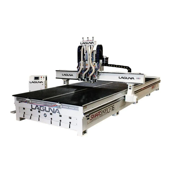
Smartshop (SUV II) Composite Fabricator 16
2021
Features:
•Huge machining area 5' x
16' —1500mm x 4800mm
*Custom sizes available
•Unique Pressure "Shoe"
design for optimum depth
accuracy- even if the panel is
not completely flat
•Helical Rack and Pinon
drives on X and Y axes. Ball
screw on Z axes
•1,2 and 3 spindle design.
Also available with ATC
spindle.
•(3) 6HP Italian HSD spindles
shown on machine below.
© 2021, Laguna Tools, Inc. LAGUNA® and the LAGUNA Logo® are the registered trademarks of Laguna Tools, Inc. All rights reserved.
Advertisement
Table of Contents

Related Manuals for Laguna Tools Smartshop Composite Fabricator 16


Summary of Contents for Laguna Tools Smartshop Composite Fabricator 16
- Page 1 •1,2 and 3 spindle design. Also available with ATC spindle. •(3) 6HP Italian HSD spindles shown on machine below. © 2021, Laguna Tools, Inc. LAGUNA® and the LAGUNA Logo® are the registered trademarks of Laguna Tools, Inc. All rights reserved.
- Page 2 Table of Contents Receiving and CNC Introduction: Pg. 4. Machine Set-Up: Pg. 5-8. Parts and Main Components of the Smartshop (SUVII) Composite Fabricator: Pg. 9-10. Glossary of Main Components of the Smartshop (SUVII) Composite: Pg. 11-12. More & Additional Safety Information for CNC Machine: Pg. 13. Machine Set-Up: Pg.
-
Page 3: Table Of Contents
Maintenance & Trouble Shooting: Pg. 52. Schematics: Pg. 53-66. Machine Set-Up: Pg. 67-68. Delivery Protocol: Pg. 69. Warranties: Pg. 70-73. Laguna Tools Packaging/RMA Procedures: Pg. 74. Laguna Tools Packaging/Laguna Tools RMA Example: Pg. 75. Laguna Tools Packaging/Laguna Tools BILL of LADING Example: Pg. 76... - Page 4 You must then contact the seller, Laguna Tools, within 24 hours. It is probable that you will find sawdust on your Smartshop II. Laguna endeavors to test all machines prior to shipping.
- Page 5 Machine Set-Up: CNC Machine (SUV II) CF 16: Machine Set-Up IMPORTANT: In order for installation to be efficient and cost effective we require several items to be completed PRIOR to our Technician’s arrival. Should you have any questions please feel free to call our Customer Service at 1-800-234-1976 or contact your Sales Representative. Following are the steps you have to perform in order for us to schedule the set-up/training- 1.) Remove all protective coating and packaging.
- Page 6 9.) Make sure the Associates has been trained in the software prior to set-up/training. Should a technician representing Laguna Tools not be able to come to the site and work on the machines due to the lack of preparedness or inoperable equipment per the above and/or beyond Laguna Tools control any expenses incurred will be passed on to you.
- Page 7 Machine Set-Up (Cont’d.): CNC Machine (SUV II) CF 16: Machine Set-Up IMPORTANT: In order for installation to be efficient and cost effective we require several items to be completed PRIOR to our Technician’s arrival. Should you have any questions please feel free to call our Customer Service at 1-800-234-1976 or contact your Sales Representative. Following are the steps you have to perform in order for us to schedule the set-up/training- 1.) Remove all protective coating and packaging.
- Page 8 9.) Make sure the Associates has been trained in the software prior to set-up/training. Should a technician representing Laguna Tools not be able to come to the site and work on the machines due to the lack of preparedness or inoperable equipment per the above and/or beyond Laguna Tools control any expenses incurred will be passed on to you.
- Page 9 Parts and Main Components of the Smartshop (SUVII) Composite Fabricator- Gantry Vacuum Table Caterpillar & Bed Track Foot w/Foot Level Caterpillar Track Vacuum Controls Frame...
- Page 10 Parts and Main Components of the Smartshop (SUVII) Composite Fabricator (Cont’d.)- Tool Changer/Clips Air Regulator System Dust Collector Green Spindle Release Button Electrical Cabinet & Control Panel Seal Gaskets for Clamp & T-Slot Vacuum Bed Work Locator Pins...
- Page 11 Glossary of Main Components of the Smartshop (SUVII) Composite Fabricator (Cont’d.)- 1. Bed: The bed of the machine consists of a heavy steel frame with a plastic top that is slotted for the vacuum function. The table has “T-Slots” in the table, which are used to clamp the job or fixtures to the bed. 2.
- Page 12 Glossary of Main Components of the Smartshop (SUVII) Composite Fabricator (Cont’d.)- 8. Vacuum Table: Vacuum table has 6 zones for flexible use. 9. Tool Changer: Tool changer has 8 stations to accommodate a large range of tools. 10. Oiler: The oiler connects to all the relevant slides on the machine and when pumped by hand will lubricate all the relevant slides.
- Page 13 More & Additional Safety Information for CNC Machine- Where to locate your machine: Before you unpack your machine, select the area where you will use your machine. There are no hard-and-fast rules for its location, but below are a few guidelines. 1.) There should be an area around the machine suitable for the length of wood that you will be machining.
- Page 14 Machine Set-Up: CNC Machine (SUV II) CF 16: Machine Set-Up IMPORTANT: In order for installation to be efficient and cost effective we require several items to be completed PRIOR to our Technician’s arrival. Should you have any questions please feel free to call our Customer Service at 1-800-234-1976 or contact your Sales Representative. Following are the steps you have to perform in order for us to schedule the set-up/training- 1.) Remove all protective coating and packaging.
- Page 15 9.) Make sure the Associates has been trained in the software prior to set-up/training. Should a technician representing Laguna Tools not be able to come to the site and work on the machines due to the lack of preparedness or inoperable equipment per the above and/or beyond Laguna Tools control any expenses incurred will be passed on to you.
- Page 16 Fitting the Router Bit into the Router Head- Safety Note: Before changing or fitting the router bit, always disconnect the power from the machine. 1.) Select a router bit and its relevant collet. 2.) Fit the collet into the spindle nut. Press the collet into the spindle nut until it snaps into place. Note: The router bit must not be fitted into the collet until the collet has been fitted into the spindle nut.
- Page 17 Fitting the router bit into the router head (Cont’d.)- 3.) Fit the Spindle Nut and Collet Assembly onto the Tool Holder and thread by hand. 4.) Press the bit into the Collet, please note that the flute of the Router Bit must not be inside the Collet and should be a minimum of 1/16"...
- Page 18 Machine Operation- Manual Tool Release: The tool holder can be released from the spindle manually by pressing the green manual release button. Note: When the green manual release button is pressed, the clamping method is released and the tool will fall out.
- Page 19 Manual Tool Release- Manual Tool Release Button- The tool holder can be released from the spindle manually by pressing the green manual release button. Note: When the green manual release button is pressed, the clamp will be released and the tool will fall out. 1.) Place your hand so that the tool holder (not the cutter) is supported.
- Page 20 Types of Router Bits that can be used- Types of Router Bits- There are five (5) basic types of router bits: 1.) Straight, 2.) Up Shear 3.) Down Shear, 4.) Combination (also called compression), and 5.) Form Tools (round over, ogee, etc.). 1.) Straight Router Bits: These are the standard router bits that are commonly used with handheld routers and are readily available at home centers.
- Page 21 Types of Router Bits that can be used (Cont’d.)- 3.) Down Shear Router Bits: These bits are similar to the up shear but with an opposite spiral that actually tends to pack the chips into the kerf. These bits prevent chipping the material surface, especially with veneers or melamine surfaces. 4.
- Page 22 Types of Router Bits that can be used (Cont’d.)- 5.) Form Router Bits- Form Router Bits typically are available in standard profiles such as round over, ogee, etc. Router bits that have a shape associated with them would be classified with this group. Home Switches- Home switches.
- Page 23 Water Pump (Optional) Connecting the water pipes to the pump (If Ordered)- Connecting the water pipes to the pump (if ordered): Safety Note: Never run the water-cooled motor without the cooling being connected, or the motor could be damaged. It is recommended that the pump be run for at least 5 minutes after the motor has been switched off to remove any residual heat.
- Page 24 Water Pump (Optional) Connecting the water pipes to the pump (If Ordered)- 4.) Place the Water Pump into 8.) Place pale underneath the Pail. the Work Bench/Workstation or any place that the Pale is not in the way. 5.) Place the black electrical cord 9.) Place the 110v of the Water Pump into the slot Electrical Plug of the...
- Page 25 Location Pins- Optional location pins [optional]. The machine can be supplied with 5 (Five) pneumatic-activated location pins. The pins can be extended or retracted by activation of the “Blue” Button on the Control Panel of the Electrical Cabinet. The pins are used as a convenient way to locate a sheet or job onto the vacuum table.
- Page 26 Tools Clips- Tools Clips or Automatic Tool Changer (ATC) Tool Changer: The tool changer consists of a number of tool spindle docking stations (up to a maximum of 8, depending on what was ordered with the machine). The machine knows the location of the docking stations and will recover and deposit tool spindles as commanded by the program that it is running.
- Page 27 Automatic Tool Contact Button or Tool Touch Off- Area for Tool/Cutter to Touch to establish height adjustment. Automatic Tool Contact Button or Tool Touch-Off (TTO) The machine is provided with an Automatic Tool Contact Button that, when used, will tell the machine the exact dimension of the tip of the tool in relation to the tool.
- Page 28 From “Set-Up” Screen to CNC Tool Data- “Tools Screen”: This page is used for all data regarding Tooling Dimensions and Offsets “Manual Setting of Tool length” = “Execute Automatic Touch Off (TTO)” Use the Jog function to move the = Select the tool in which needs to be cutter to the table or work surface.
- Page 29 Electrical Cabinet & Control Panel- Emergency Stop Button Power On/Off Button USB Socket/Port Display Spindle Frequency Display Vacuum Pump On/Off Switch 1 & 2. Electrical On/Off Switch Position Rod Switch The Control Panel houses the main interface to the machine. 1.
- Page 30 Turning on the Machine- Turning on the Machine: Note: Before you turn on the machine, remove all tools and other objects from the machine table. Make sure that the table surface is clear of obstructions. 1.) Release the emergency stop by twisting clockwise, and it will pop out. 2.) Turn the On/Off switch to turn the power “On”.
- Page 31 Turning on the Machine (Cont’d.)- Turning on the Machine: Note: Before you turn on the machine, remove all tools and other objects from the machine table. Make sure that the table surface is clear of obstructions. 4.) Press “MAIN/HOME MACHINE” button.
- Page 32 Main Screen Button(s) & Flow- “Main” Screen...
- Page 33 Main / Home Screen Defined- Above is the Start-Up Home Screen- Park Tool = Pressing this button will put the active tool in spindle into its tool holder and leave the spindle empty. Preventive Maintenance Note- *****One should never leave a tool in spindle when machine is Idle. Leaving a tool in spindle will cause rust and damage to tool holder and or spindle.
- Page 34 Main / Home Screen Defined- Hold Settings Preview Program Hold = The Hold button is used to Pause a program run. Press the Run button to continue. NOTE: The spindle stays running during hold. Press stop button to stop the spindle and program. Run = The Run button is used to start a CNC Program.
- Page 35 Main / Home Screen Defined (Cont’d.)- Right Side Fields defined: Select Program drop down window = This field allows you to quickly select a program from the files copied to the controller’s memory. Active Tool = This references the current tool in spindle.
- Page 36 Main / Home Screen Defined (Cont’d.)- CNC Monitor = These 5 lines are displaying the CNC “G”- Code as it is running Coord’s Selector/Lower Right Drop Down = This is the selector for the X,Y, and Z coordinates displayed at the bottom of the Main Page.
- Page 37 Main Screen Buttons & Flow to proceed to CNC Positions- 1. Make sure one is in “Machine Coordinates”. “Set-Up” Screen Appears- 2. From the “Main Screen” select the “SET UP” Button, then it will proceed to “Set-Up” Screen.
- Page 38 Loading a Program into the Machine- Loading a Program into the Machine: .) Load your program into your USB drive. USB Drive to Transfer Files. 2.) Fit the USB into the USB slot. 3.) Press the “MAIN” Button to get to the Main/Home Screen. 4.) Within the Main/Home Screen, go to and Press the “SET-UP”...
- Page 39 Loading a Program into the Machine- From the “Main Screen” select the “Program Manager” Button, then it will proceed to “SET-UP” Screen appears.
- Page 40 Loading a Program into the Machine (Cont’d.)- 5.) Press the “Program Manager” Button & the Screen that is shown will appear.
- Page 41 Loading a Program into the Machine (Cont’d.)- “USER TAB” – TO THE CUSTOMER DO NOT UTLIZE OR USE IN ANY WAY. “Programs Tab” – This displays the programs within a specified folder. “Copying Programs to the Controller” - A program must be selectable from the Programs Tab in order to be made active.
- Page 42 Loading a Program into the Machine (Cont’d.)- 6.) Press the “USB Tab” Button to Display Program(s) within a Specific Folder. “Refresh Button” = This buttons polls the program storage area and brings the list up to a real time reference. 7.) Press the “Programs Tab”...
- Page 43 Activate Start Program/File in the Machine - Safety Note: Ensure that you are cleared of the machine. The spindle will start to rotate and could cause injury. 11.) To start Program, Go to the “Main Menu”, Press “Main”. 12.) When the Main Menu appears, Go to “Select Program” Area. 13.) Go to the Dropdown Menu &...
-
Page 44: Using The Vacuum Table & Vacuum Zones
Using the Vacuum Table & Vacuum Zones- Using the Vacuum Table: Note-The better the vacuum that is created, the more secure the parts will be held in place. Follow the below instructions to obtain optimum results. The Vacuum Table has 6 Zone’s and you can set the configuration to suite the type of work that you will be producing. Each zone is controlled by a On/Off Switches that is located at the front of the machine. - Page 45 Using the Vacuum Table & Vacuum Zones- The table has holes in each zone that extract the air and generate the vacuum. The table has grooves that ensure that the air is extracted evenly across the zone. T-Slots are also provided to allow you to clamp jobs / spoil boards to the table should it be required.
-
Page 46: Fitting The Foam Rubber Gasket
Fitting the Foam Rubber Gasket- It is important that the foam rubber gasket is pressed evenly into the grove in the vacuum table around the zone that you are constructing. To ensure a good seal, it is strongly recommended that the gasket be turned in at the beginning (as shown). The gasket has a tendency to stretch while fitting, and over time it may relax and shorten. -
Page 47: Spoil Board Material And Precautions
1/2-inch thick, discard and start a new spoil board. The spoil board edges are very porous and must be sealed. Laguna Tools recommends that a “Hard Candle Wax” be used, as it contains no water. - Page 48 Spoil Board Material and Precautions (Cont’d.)- Note: Even some glues contain water and can affect the edges of the spoil board. Note: Do not confuse flatness with bow. If the board is bowed, the vacuum may not pull the board down and you will lose vacuum.
- Page 49 Spoil Board Material and Precautions (Cont’d.)- Spoil Board: The spoil board must cover the complete table and sit on the flats around the table. If the spoil board does not cover all the vacuum slots, the vacuum will be lost, and your job will not be pulled down onto the spoil board. Fitting the Foam Rubber Gasket: It is important that the foam rubber gasket is pressed evenly into the groove in the vacuum table around the zone that you are constructing.
- Page 50 Spoil Board Material and Precautions (Cont’d.)- Note: Do not stretch the foam rubber gasket while you are fitting it into the groove in the vacuum table. Removing the Job from the MDF Spoil Board: The job has a tendency to stick to the spoil board, and it is suggested that you use a wide blade putty knife to lift the job.
-
Page 51: Securing Job To Table
Securing Job to Table- Fitting the job to the table using the T-Slots. You may find it convenient to clamp the job to the spoil board with the table clamps. This attachment method can only be used if the outside edges are not being machined. When using the clamps, place a piece of packing under the jacking bolt to protect the bed of the machine. -
Page 52: Maintenance & Trouble Shooting
Maintenance & Trouble Shooting- DO’S AND DON’TS: 1.) DO verify water level in the spindle reservoir. 2.) DO lubricate all ball screws every 8 hours of run. Use 30w oil or lithium white grease lubricant or equivalent to lubricate the ball screws and wipe off any excess to reduce dirt and dust acumination. -
Page 53: Schematics
Schematics-... - Page 54 Schematics (Cont’d.)-...
- Page 55 Schematics (Cont’d.)-...
- Page 56 Schematics (Cont’d.)-...
- Page 57 Schematics (Cont’d.)-...
- Page 58 Schematics (Cont’d.)-...
- Page 59 Schematics (Cont’d.)-...
- Page 60 Schematics (Cont’d.)-...
- Page 61 Schematics (Cont’d.)-...
- Page 62 Schematics (Cont’d.)-...
- Page 63 Schematics (Cont’d.)-...
- Page 64 Schematics (Cont’d.)-...
- Page 65 Schematics (Cont’d.)-...
- Page 66 Schematics (Cont’d.)-...
-
Page 67: Machine Set-Up
Machine Set-Up- CNC Machine CF Machine Set-Up IMPORTANT: In order for installation to be efficient and cost effective we require several items to be completed PRIOR to our Technician’s arrival. Should you have any questions please feel free to call our Customer Service at 1-800-234-1976 or contact your Sales Representative. Following are the steps you have to perform in order for us to schedule the set-up/training- 1.) Remove all protective coating and packaging. - Page 68 9.) Make sure the Associates has been trained in the software prior to set-up/training. Should a technician representing Laguna Tools not be able to come to the site and work on the machines due to the lack of preparedness or inoperable equipment per the above and/or beyond Laguna Tools control any expenses incurred will be passed on to you.
-
Page 69: Delivery Protocol
Delivery Protocol- • Most large machinery will be delivering on a tractor trailer 48'-53' long. Please notify Sales Representative with any Delivery Restrictions. • Customer is required to have a forklift (6000lb. or larger is recommended) with 72" forks or fork extensions and operator. •... - Page 70 Laguna Tools guarantees all new machine sold to be free of manufacturers’ defective workmanship, parts and materials. We will repair or replace, without charge, any parts determined by Laguna Tools, Inc. to be a manufacturer’s defect. We require that the defective item/part be returned to Laguna Tools with the complaint. The end-user must request an RMA (return material authorization) number from Customer Service and include the (RMA) number with any and all returned parts/components requesting warranty coverage.* Any machines returned to Laguna Tools must be returned with packaging in...
- Page 71 Technical support to install replacement parts is primarily provided by phone, fax, e-mail or Laguna Tools Customer Support Website. The labor required to install replacement parts is the responsibility of the user. Laguna Tools is not responsible for damage or loss caused by a freight company or other circumstances not in our control.
- Page 72 Laguna Tools Warranty-...
- Page 73 Parts, under warranty, are shipped at Laguna Tools, Inc.’s cost either by common carrier, FEDEX ground service or a similar method. Technical support to install replacement parts is primarily provided by phone, fax, e-mail or Laguna Tools Customer Support Website. The labor required to install replacement parts is the responsibility of the user.
-
Page 74: Laguna Tools Packaging/Rma Procedures
We require that the defective item/part be returned to Laguna Tools with the complaint. The end-user must request an RMA (Return Material Authorization) Number from Customer Service and include the (RMA) number with any and all returned parts/components requesting warranty coverage. -
Page 75: Laguna Tools Packaging/Laguna Tools Rma Example
Laguna Tools Packaging/Laguna Tools RMA Example- RMA #... -
Page 76: Laguna Tools Packaging/Laguna Tools Bill Of Lading Example
Laguna Tools Packaging/Laguna Tools BILL of LADING Example-... - Page 77 Manual Revision Record Date of Change Revision# Engineering/Design Change Description New Manual for the Smartshop CF. 5/12/2021...
Need help?
Do you have a question about the Smartshop Composite Fabricator 16 and is the answer not in the manual?
Questions and answers