Table of Contents
Advertisement
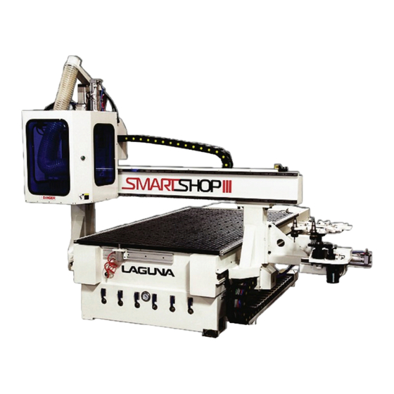
Smartshop III
CNC Router Manual
SmartShop III 5x10 HSD wo Drill Block
SmartShop III 5x12 HSD w/ ATC - Without Drill Block
SmartShop III 5x12 HSD w Drill Block
LAGUNA TOOLS
2072 Alton Parkway
Irvine, California 92606
Ph: 800.234.1976
www.lagunatools.com
© 2018, Laguna Tools, Inc. LAGUNA® and the LAGUNA Logo® are the registered trademarks of Laguna Tools, Inc. All rights reserved.
Model Numbers MCNC SS3 5x10 HSD NO Drill Block
MCNC SS3 5x12 HSD NO Drill Block
MCNC SS3 5x12 HSD NO Drill Block
Advertisement
Table of Contents

Related Manuals for Laguna Tools Smartshop III Series


Summary of Contents for Laguna Tools Smartshop III Series
- Page 1 Irvine, California 92606 MCNC SS3 5x12 HSD NO Drill Block Ph: 800.234.1976 MCNC SS3 5x12 HSD NO Drill Block www.lagunatools.com © 2018, Laguna Tools, Inc. LAGUNA® and the LAGUNA Logo® are the registered trademarks of Laguna Tools, Inc. All rights reserved.
-
Page 3: Table Of Contents
Table of Contents GENERAL INFORMATION ........................... 5 1.1..............................5 AFETY ULES 1.2............................. 6 IMITED ARRANTY 1.3..............................7 OISE EMISSION 1.4............................7 PECIFICATION SHEET 1.5............................. 7 ECEIVING YOUR MACHINE 1.6..............................8 AINTENANCE 1.6.1. Lubrication ............................8 1.6.2. - Page 4 2.5.2. Tool Display Section ........................... 52 2.5.3. Drill Block Buttons ..........................53 2.5.4. Tool Offset Preset ..........................55 2.5.5. Spindle Buttons........................... 56 2.5.6. Tool Changer ............................57 2.5.7. Page Buttons ............................59 2.5.8. Operation Buttons ..........................60 2.6............................61 ENGTH ABLE 2.7.
-
Page 5: General Information
General Information Safety Rules As with all machinery, there are certain hazards involved with the operation and use of your machine. Using it with caution will considerably lessen the possibility of personal injury. However, if normal safety precautions are overlooked or ignored, personal injury to the operator may result. -
Page 6: Limited Warranty
Machines sold through dealers must be registered with Laguna Tools within 30 days of purchase to be covered by this warranty. Laguna Tools guarantees all new machines and accessories sold to be free of manufacturers’... -
Page 7: Noise Emission
All damage must be noted on the delivery documents and signed by you and the delivery driver. You must then contact the seller, Laguna Tools, within 24 hours. It is advisable to photograph any shipping damage to support an insurance claim. -
Page 8: Maintenance
Maintenance Lubrication You must regularly (minimum every 12 hours) lubricate the rails. Use a thin layer of 30wt oil lubricant. Spray daily and wipe off the excess. Daily checks 1. Clean the machine and lubricate unpainted surfaces with a 30wt oil lubricant. Wipe off any excess and buff with a dry polishing cloth. -
Page 9: Glossary Of Terms
Glossary of terms Boot Controller – The window used to boot the machine. Process Control Window – The window that contains all the control screens for the machine. It includes the Main screen, Axis + Spindle Screen and Tool Screen. Page. - Page 10 Main Screen – the screen that shows the active button, MDI button, and the active G-Code. Axis + Spindle Screen – The screen that allows the user to move the spindle manually. Page. 10...
- Page 11 Tool Screen –The screen that displays tool information. Manual Pulse Generator (MPG) – The axis Page. 11...
-
Page 12: Operation Basics
Operation Basics Turning On the Machine 1. Make sure there is no object or people near the machine that can be damaged by machine movement. 2. Rotate the main contact switch clock-wise until it clicks in place. 3. Press the PC power button. Page. - Page 13 4. Press the controller power button. There might be an additional controller on button that needs to be pressed, depend on your machine setup. 5. The Boot controller will load as in picture below. Page. 13...
- Page 14 6. Press the Normal Mode button. 7. Wait for the machine to start up. Once start up is completed, the Process Control window will display the Main screen as in picture below. Notice that there is a message box that displays “001 EMERGENCY STOP ACTIVE.”...
- Page 15 8. Make sure the E-stop is released by rotating it clockwise. 9. Click on the E-STOP RESET button. This will clear the emergency stop mode. Page. 15...
- Page 16 10. Notice that the message box displays “011 AXIS NOT REFFERENCED”, it is because the machine needs to be homed at start up. Click the home button , machine will start moving to its homing position. 11. Wait until the machine has finished homing. The machine should now have no message in the message box.
-
Page 17: Shutting Down The Machine
Shutting Down the Machine 1.) Make sure nobody can be harmed by machine movement. 2.) Click on the MDI button to enable MDI input. Page. 17... - Page 18 3.) Enter “M6T0” in the dialogue box then press Confirm. 4.) Press the RUN button , the machine will put away the tool in spindle. Putting away the tool in spindle at the end of the day prevents the spindle from rusting. Page.
- Page 19 5.) Close the process controller window by clicking the “X” button on the upper right corner of the window. 6.) Close the boot controller window my clicking the “X” button on the upper right corner of the window. Page. 19...
- Page 20 7.) Select start -> shutdown 8.) Click on the shutdown button, and then wait for the computer to shut down. Page. 20...
- Page 21 9.) Press the red button to shutdown the controller 10.) When the computer has been shut down, turn off the main contactor by rotating it counter- clockwise. Page. 21...
-
Page 22: Main Screen
Main Screen The main page will load up at machine start up. The sections are explained below. Page. 22... -
Page 23: Top Toolbar Section
Top Toolbar section Table editor button – opens the table editor window. The rest of the buttons are reserved for use by Laguna Tools technicians. Page. 23... -
Page 24: Cnc Display Section
CNC NAME – The name of the CNC machine being controlled. PROCESS – This field is reserved for use by Laguna Tools technicians. MODE – Whether the machine is in AUTO mode or MANUAL mode. AUTO mode allows the machine to run G-code programs and MANUAL mode allows the user to move the spindle manually. -
Page 25: Tool Display Section
Diam – Diameter of the curent tool. X Offset – the X offset of the current tool, this is factory set and is only used by Laguna Tools technician. Y Offset – the Y offset of the current tool, this is factory set and is only used by Laguna Tools technician. -
Page 26: Function Display Section
Function Display Section This section displays whether each machine functions are on or off. They are reserved for use by Laguna Tools technicians. Page. 26... -
Page 27: Modal G-Code/M-Code Display Section
Modal G-Code/M-Code display section This section displays the modal G-Code and M-Code currently active. Please reffer to “Appendix, G-Code List”, and “Appendix, M-Code List” for detail. Page. 27... -
Page 28: Active G-Code Program Section
Below is a description of each display: Last Block N – Number of the last block ran. Selected PP – Reserved for use by Laguna Tools technicians. Subprogram – Reserved for use by Laguna Tools technicians. Program Message – First few lines of the active G-Code. -
Page 29: Coordinate Display Section
Coordinate display section This section displays the programmed position and actual position of the spindle. When the origin display column displays “0”, the displayed coordinate is in Machine Coordinate When the origin display column displays “1”, the displayed coordinate is in Work Coordinate 1, which can be activated by the command “(UAO, 1)”. -
Page 30: Feed And Speed Section
Feed and Speed Section This section shows the programmed speed, override percentage, and actual speed of the spindle. The programmed speed is multiplied by the override percentage to result in the actual speed. The machine moves at the actual speed. The override percentage can be changed using the override buttons which will be explained in more detail in the next section. -
Page 31: Override Buttons
Override Buttons The override buttons allows the user to adjust the feed rate and speed override. Below are the descriptions: - Feed rate button, used to adjust the override percentage of the feed rate. - Spindle button, used to adjust the override percentage of the spindle speed. Page. -
Page 32: Page Buttons
Page buttons These buttons allows the user to move to different pages of the Process Control Window, and clear messages. I/O Button – go to I/O page. It lists different input output ports. Tools Button – go to the tool page. Axis+Spindle Button –... -
Page 33: Function Buttons
Function Buttons Jump - Memory search button – used to return to the last line of G code executed after unexpected system shutdown. For example, a power outage. Block number button – used for run from a specific line number. Page. - Page 34 MPG Run Mode – When running G-Code with this button the feed rate will depend on the speed in which the user rotates the MPG main wheel. It is used to test out a G-Code slowly while allowing the user to pause. - Find Zero Button –...
-
Page 35: Pneumatics Control Buttons
Pneumatics Control Buttons Dust hood control – lifts and drops the dust hood. Vacuum button – turns the first vacuum pump on and off. Vacuum 2 button – turns the second vacuum pump on and off. Pop –Up Pin Button – raise and lowers the pop-up pins used to locate the work piece. Vacuum table on (Optional) - There might be a Vacuum table on button if your machine is fitted with a butterfly valve for the vacuum table. -
Page 36: Operation Mode Selection Button
Operation Mode Selection Button MDI – used to input command manually. Auto mode button – auto mode allows continuous G code as well as MPG Run mode when the MPG button is pressed. Block by Block Mode – runs G-code one line at a time. Page. -
Page 37: Operation Buttons
Operation Buttons Run Button – used to start running a G code Pause Button – used to pause a G code while it is running. To continue running, press the pause button again to unpress it, then press the Run button again. Reset Button –... -
Page 38: Bottom Toolbar
Bottom Toolbar Only two buttons on this tool bar is used, the other buttons are reserved for used by Laguna Tools technicians. Below are the descriptions for the two buttons: Origin/Tool button – Used to set work origin. Please see the section “Setting Work Origin”... -
Page 39: Axis + Spindle Screen
Axis + Spindle Screen The Axis + Spindle Screen can be accessed by pressing the Axis + Spindle button from the main screen and the tool screen. Here are the descriptions on the different parts of this screen. Page. 39... -
Page 40: Axis Buttons
Axis Buttons Axis buttons, used to move the axis in continuous job mode or step jog mode. Please read “Continuous Joging”, and “Step Jogging” sections for detail. There might be additional buttons if your machine has additional axis. Page. 40... -
Page 41: Feed And Speed Section
Feed and Speed Section This section shows the programmed speed, override percentage, and actual speed of the spindle. The programmed speed is multiplied by the override percentage to result in the actual speed. The machine moves at the actual speed. The override percentage can be changed using the override buttons which will be explained in more detail in the next section. -
Page 42: Speed/Distance Setting
Speed/Distance Setting The override buttons allows the user to adjust the feed rate and speed override. Below are the descriptions: - Feed rate button, used to adjust the override percentage of the feed rate. - Spindle button, used to adjust the override percentage of the spindle speed. Page. - Page 43 Jog increment control – controls the step jog increment, that is the distance an axis will travel in step jog mode. Page. 43...
-
Page 44: Spindle Control
Spindle Control These buttons are used to control the spindle, below is the description: Spindle Reverse Run – Not in use. Spindle Forward Run – Turns on the spindle to preset RPM. Page. 44... - Page 45 Spindle Stop – Stops the spindle when it is on. Spindle Up – Raises and drops the spindle. The spindle needs to be dropped when machining using the spindle and it needs to be raised when using the drill block. RPM Setting –...
-
Page 46: Page Buttons
Page Buttons These buttons allows the user to move to different pages of the Process Control Window, and clear messages. Tools Button – go to the tool page. Main Button – go to the Main page. Clear Message Button – used to clear messages in the yellow message box. An message can only be cleared if the cause of the message had be alleviated. -
Page 47: Jogging Mode Buttons
Continuous jog mode button – used to put the machine into continuous jog mode. Step jog mode button – used to put the machine into step jog mode. Button not in use - Reserved for use by Laguna Tools technicians. Page. 47... - Page 48 Single axis home button – Used to put the machine into single axis home mode. When in this mode, press the desired axis button to home it. MPG – Manual Pulse Generator; used to put the machine into hand wheel control mode. Page.
-
Page 49: Operation Buttons
Operation Buttons Pause Button – used to pause a G code while it is running. To reset, click the reset button. Reset Button – used to stop a G code while the system is moving. Page. 49... -
Page 50: Tool Screen
Tool Screen Page. 50... -
Page 51: Cnc Display Section
CNC Display Section Please see”Error! Reference source not found. CNC Display Section” for reference. Page. 51... -
Page 52: Tool Display Section
Diam – Diameter of the curent tool. X Offset – the X offset of the current tool, this is factory set and is only used by Laguna Tools technician. Y Offset – the Y offset of the current tool, this is factory set and is only used by Laguna Tools technician. -
Page 53: Drill Block Buttons
Drill Block Buttons Note that some machine might not have the drill block, thus will not have these buttons. through - Single Drill Actuation Button – raise and drops a single drill bit on the drill block. Click once to drop a drill bit, click again to raise it. All Up Button –... - Page 54 All Down Button – Drops all of the drill bits on the drill block. Multi-spindle Start – Turns on the drill block rotation. Press this button again to turn the drill block off. Page. 54...
-
Page 55: Tool Offset Preset
Tool Offset Preset This section is used to set tool offset and tool length. Please read the section “Setting Tool Length” for more detail. Page. 55... -
Page 56: Spindle Buttons
Spindle Buttons Spindle Up – Raises and drops the spindle. The spindle needs to be dropped when machining using the spindle and it needs to be raised when using the drill block. Tool Release – When clicked, the spindle will release the tool it is holding. Dust hood control –... -
Page 57: Tool Changer
Tool Changer Tool Changer Slide – Slides the tool changer. Tool Changer Rotation (counter-clockwise) – rotate the tool changer counter-clockwise by one increment. Tool Changer Rotation (clockwise) – rotate the tool changer clockwise by one increment. Page. 57... - Page 58 Requested Pocket – pocket requested by the G-Code. Current Pocket – The current active tool changer pocket. Page. 58...
-
Page 59: Page Buttons
Page Buttons Axis + Spindle Button – go to the axis + spindle page. Main Button – go to the Main page. Clear Message Button – used to clear messages in the yellow message box. A message can only be cleared if the cause of the message had been alleviated. Page. -
Page 60: Operation Buttons
Operation Buttons Pause Button – used to pause a G code while it is running. To reset, click the reset button. Reset Button – used to stop a G code while the system is moving. Page. 60... -
Page 61: Tool Length Table
Tool Length Table The tool length table displays the tool length and offset for a particular tool. Here are the instructions to open the Tool Length Table. 1. From the Main screen, click on the Table Editor button Page. 61... - Page 62 2. Click on the Tool Length Table button. 3. Click on the desired tool and enter number in the desired field, then press apply to apply the change. Page. 62...
-
Page 63: Work Origin Table
Work Origin Table The work origin table displays the X,Y, Z offset for a particular tool. Here are the instructions to open the Work Origin Table. 1. From the Main screen, click on the Table Editor button Page. 63... - Page 64 2. Click on the Work Origin Table button. 3. Click on the desired work origin and enter number in the desired field, then press apply to apply the change. Page. 64...
-
Page 65: Operation Procedures
Operation Procedures Jogging the machine Jogging the machine refers to manually telling the machine to move its X, Y, or Z axis. There are three ways to jog the machine: Continuous Jogging, Step Jogging , and MPG jogging. Continuous jogging is used to move the machine over a long range, since it allows jogging at a high speed. - Page 66 3. From the Axis + Spindle Screen, press the Continuous Jog Button. 4. Use the feed rate buttons to adjust the feed rate percentage. The higher the percentage the faster the machine will move. Page. 66...
- Page 67 5. Press and hold the axis buttons to move the machine. On a touch screen, there is a safety delay so that the user needs to hold the button for about one second before the machine starts moving. 6. If an axis limit message shows up, jog the machine away from its positive or negative limit. Page.
-
Page 68: Step Jogging Procedure
Step Jogging Procedure 1. Make sure nobody can be harmed by any machine movements and that there is nothing that obstructs machine movements. 2. From the Main Screen, click the Axis + Spindle Button to go to the Axis + Spindle page. Page. - Page 69 3. From the Axis + Spindle Screen, press the Step Jog Button. 4. Use the Jog Increment buttons to adjust the Jog Increment. The Jog Increment is the distance an axis will move when it is clicked. Page. 69...
- Page 70 5. Single click the axis buttons to move the machine. 6. If an axis limit message shows up, jog the machine away from its positive or negative limit. Page. 70...
-
Page 71: Manual Pulse Generator (Mpg)
Manual Pulse Generator (MPG) 1. Make sure nobody can be harmed by any machine movements and that there is nothing that obstructs machine movements. 2. From the Main Screen, click the Axis + Spindle Button to go to the Axis + Spindle page. 3. - Page 72 4. Use the middle knob on the MPG to select the axis to move. 5. Use the bottom knob to select speed, with 100X being the fastest. Page. 72...
- Page 73 6. Rotate the top knob clockwise to move the axis in the positive direction and counter-clockwise for negative direction. 7. After the manual jog is completed, turn the middle knob to the “Off” position to prevent machine movement by accident. 8.
-
Page 74: Setting Tool Length
Setting Tool Length Please refer to the 5-Axis manual for Setting Work tool length on a 5-Axis machine. 1. Make sure nobody can be harmed by any machine movements and that there is nothing that obstructs machine movements. 2. Make sure it is safe to drop the spindle or drill, whichever applies. That is, make sure the Z axis is high enough that dropping the spindle or the drill will not cause it to hit anything. - Page 75 5. From the Main page click Tools button to go to the tool page. 6. Select the Z axis at Tool Offset Preset field. Page. 75...
- Page 76 7. Enter the tool number for Offset Number field then press “Enter” key on keyboard. The tools in main spindle are tools 1 through 8, depend on its location in the tool holder. The drill bits in the drilling block has tool numbers from 11 to 19. 8.
-
Page 77: Setting Work Origin
Setting Work Origin Please refer to the 5-Axis manual for Setting Work Origin on a 5-Axis machine. 1. Make sure nobody can be harmed by any machine movements and that there is nothing that obstructs machine movements. 2. Manually jog the machine to a X,Y coordinate you wish to set as the Work Origin. The Z coordinate does not matter. - Page 78 4. Click on the Origin Preset option. 5. Enter the desired offset number. There are nine off sets, from 1 to 9. The offset is activated in G- Code with the syntax “(UAO, 1)” where “1” can be any number from 1 to 9. Page.
- Page 79 6. Enter “0” for both X and Y, and leave Z blank. If the machine has a C axis, please leave that blank as well. 7. Click OK. The Work Origin is now set. Page. 79...
-
Page 80: Running A G-Code File
Running a G-Code File 1. Make sure nobody can be harmed by any machine movements and that there is nothing that obstructs machine movements. 2. Make sure the Tool Length and Work Origin is setup correctly. 3. Transfer the G-Code program to the machine. This can be done via a USB Disk. 4. - Page 81 5. In My Computer window, double click on the user on '192.168.0.1' (Y:) Disk 6. Double click on the PROGRAMS folder. Page. 81...
- Page 82 7. Copy the G-Code file into this folder: Y:\PROGRAMS 8. Make sure the machine is in Auto Mode by clicking on the Auto Mode button. Page. 82...
- Page 83 9. Click the Part Program button 10. Select Activate Part Program Page. 83...
- Page 84 11. If the directory isn’t expanded, click on the + sign next to expend it. Page. 84...
- Page 85 12. Select PROGRAMS drive. Page. 85...
- Page 86 13. Click on the desired G-Code file to highlight it. 14. Click on the “OK” button to activate it. Page. 86...
- Page 87 15. Upon activation, the G-Code program will be shown in the Active G-Code Program section. Page. 87...
- Page 88 16. If necessary, turn on the vacuum pumps by clicking on the vacuum pump buttons. . Also turn on the vacuum table by pressing the Vacuum table on button if necessary. 17. Make sure the work piece is secured and that machine movements will not damage any person or object.
- Page 89 18. Click on the run button. The machine will start executing the G-Code file. Page. 89...
- Page 90 19. To pause the machine movement, click the Pause Button . Note that the spindle might not stop when pausing. 20. To continue, press the Pause Button again then press Run button. Page. 90...
- Page 91 21. To Stop the program completely, press the Reset button. Page. 91...
-
Page 92: Advanced Functions
Advanced Functions MPG Run When running G-Code in MPG Run mode the feed rate will depend on the speed in which the user rotates the MPG knob. It is used to test out a G-Code slowly while allowing the user to pause. Following is the MPG Run mode procedure. - Page 93 4. Click on the MPG Run button to activate it. Page. 93...
- Page 94 5. Press the Run Button to run the G-Code file. 6. Turn the MPG’s top knob to run the program. The faster it is turned, the faster the program will run. Page. 94...
- Page 95 7. To exit the MPG Run mode, press the MPG button again then increase the Feedrate Percent by pressing the Feedrate button. Page. 95...
-
Page 96: Block By Block Mode
Block by Block Mode The Block by Block mode allows user to run a G-Code file line by line, with one line executed per click of the Run button. The following section is the procedure. 1. Activate a G-Code file by following the instructions in the “Running a G-Code File” section. 2. - Page 97 4. Click the Block by Block button . This will put the machine in Block by Block mode. 5. Click run to run a single line of the code , click Run again to run another line. Page. 97...
-
Page 98: Mdi
The MDI command allows the user to input G-Code and M-Code manually. Please refer to appendix section “MDI Commands” for a list of commands available. The following is the procedure for using MDI commands. 1. From the Main page, click the MDI button Page. - Page 99 2. Manually input the command in the command box. 3. Click confirm. Page. 99...
- Page 100 4. Click the run button. The MDI entry is completed. 5. Click Auto mode button to exit the MDI mode. Page. 100...
-
Page 101: Automatic Tool Change
Automatic Tool Change 1. Make sure that it is safe for the machine to move. 2. From the Main page, click the MDI button Page. 101... - Page 102 3. Manually input the command “M6T3” in the command box. Where T3 refers to tool number 3. To change to tool number 8, for example, enter “M6T8” 4. Click confirm. Page. 102...
- Page 103 5. Click the run button. The MDI entry is completed and the machine will change to the tool specified. 6. Click Auto mode button to exit the MDI mode. Page. 103...
-
Page 104: Automatic Tool Touchoff
Automatic Tool Touchoff Automatic tool touch off utilizes a tool touch off switch to automatically detect the length of the tool in spindle. The following section includes the procedure. 1. Make sure nobody can be harmed by any machine movements and that there is nothing that obstructs machine movements. - Page 105 4. From the Main page, click the MDI button 5. Manually input the command “M401T3” in the command box. Where T3 refers to tool number 3 currently in spindle. If tool 8 is in spindle, for example, enter “M401T8.” Page. 105...
- Page 106 6. Click confirm. 7. Click the run button. The MDI entry is completed and the machine will touch off the tool in spindle. Page. 106...
- Page 107 8. Click Auto mode button to exit the MDI mode. Page. 107...
-
Page 108: Start From Block
Start from Block Start from block function allows the user to start running a G-Code file at a specific line. The following is the procedure to use it. Note that the modal G-Code are usually at the start of the program and might be skipped when doing Start from Block. - Page 109 4. Make sure the machine is in Auto Mode by clicking on the Auto Mode button. 5. Click on the Block No. button. Page. 109...
- Page 110 6. Enter the desired block, label, or line number to start from. Then click “OK”. 7. Click the Run button to start the program. Page. 110...
-
Page 111: Memory Search Function
Memory Search Function The Memory Search function is used to find the last executed line in a file. It can be useful in the event of a power outage. 1. Make sure the machine is in Auto mode by pressing the Auto mode button 2. - Page 112 3. Click on the run button. The machine will start the memory search. Page. 112...
- Page 113 4. Wait for the process to complete. Once the memory search concluded, the machine will display “End of search in memory” on upper left corner. The last ran G-code will be highlighted in the Active G-Code area. 5. Click the reset button to clear the message and click the Memory Search button to disable Memory Search mode.
-
Page 114: Troubleshooting
Troubleshooting The menu bar is missing in the Process Controller. – Press Ctrl+M to toggle it on and off. MPG run mode is grayed out –make sure the machine is in Auto mode not MPG mode on the Axis screen, make sure there is an active program on the Main screen. The machine freezes during tool change –... -
Page 115: System Restore
System Restore System recovery sets the machine settings according to a specific recovery file. It can be used to change machine to its previous state when the machine setting is accidentally changed. 1. Unplug the touch screen USB cable from the computer. 2. - Page 116 4. Click the boot button then click “Shutdown.” 5. Click OK in the pop-up window. This will restart the controller. Page. 116...
- Page 117 6. The controller will display “CNC Connected” when the restart had finished. 7. Click on the Security icon to load the Security window. Page. 117...
- Page 118 8. From the security window, click on the Restore button. 9. Click on the browse button. Page. 118...
- Page 119 10. Navigate to the desired system backup file, it should be named “IP.192.168.0.1”. 11. Click “Open” Page. 119...
- Page 120 12. Click “Start,” the system will begin the system restore. 13. Click “Yes” when prompted with the message “Do you want to restore users level permissions?” Page. 120...
- Page 121 14. Click “No” when prompted with the message “The CNC needs to be rebooted to complete the installation. Press OK to reboot now, CANCEL if you want to manually reboot later.” Page. 121...
- Page 122 15. Click on the rocket symbol to access the boot control window. Page. 122...
- Page 123 16. Click on the Normal mode button. 17. Click Boot then click Shutdown. Page. 123...
- Page 124 18. Click “OK” to restart the controller. 19. Wait for the controller to restart. The system recovery is now completed. Page. 124...
-
Page 125: System Backup
System Backup System backup saves the system parameters into a file which can be used later to restore the system parameter. 1. Follow the system recovery procedure to access the security window. 2. Click on Backup Page. 125... - Page 126 3. Click on Browse and navigate to the desired folder to put the backup files. Note that the program will generate more than one file. The recommended format for the folder name is “07252014_CNCBackup”, where “07252014” is the current date. 4.
- Page 127 5. Click “All the control” checkbox to check it. 6. Click “Start” and wait for the recovery process to end. 7. Click on the rocket symbol to access the boot control window. Page. 127...
- Page 128 8. Click on the Normal mode button. Page. 128...
- Page 129 9. Click Boot then click Shutdown. 10. Click “OK” to restart the controller. 11. Wait for the controller to restart. The system recovery is now completed. Page. 129...
-
Page 130: Appendix
Appendix MDI Command list The MDI command box can be used to execute all G-Code, M-Code, and controller specific functions. Attached is a list of useful (UAO, 1) – activate origin 1. Replace the number 1 with the number 2 to 9 for other origins. For example, enter (UAO,2) to activate origin 2. -
Page 131: G-Code List
G-Code List G00 Rapid axes positioning G01 Linear interpolation G02 Circular interpolation CW G03 Circular interpolation CCW G04 Dwell at end of step G09 Deceleration at end of step G10 Circular interpolation for three points in space G12 CCW circular interpolation in space G13 CW circular interpolation in space G14 Linear interpolation with dynamic rapid parameters G16 Defined interpolation plane... - Page 132 G97 Spindle speed programming in rpm G72 Point probing with probe ball radius compensation G73 Hole probing with probe ball radius compensation G74 Probing for theoretical deviation from point without probe ball radius compensation G99 Deletes G92 Page. 132...
-
Page 133: M-Code List
M-Code List Some M-Code might only apply to a certain machine configurations. Spindle On Spindle Off Tool change. E.g. “M06T2” changes to tool 2. Drilling block rotation on Drilling block rotation off Main spindle tool grip Main spindle tool release Extend tool changer cylinder Retract tool changer cylinder End program... -
Page 134: Controller Specific Functions
Controller Specific Functions (UAO, 1) – Activate origin 1. Replace the number 1 with the number 2 to 9 for other origins. For example, enter (UAO,2) to activate origin 2. (DLY, 3) – Delay the program for 3 seconds. Replace the number 3 with any integer to delay the specified number of seconds. - Page 135 For technical support, contact Laguna Tools at 1-800-234-1976 email Laguna Tools customer service at customerservices@lagunatools.com Please input machine type in subject line. Page. 135...
- Page 136 Laguna Tools is not responsible for errors or omissions. Specifications subject to change. Machines may be shown with optional accessories. © 2018, Laguna Tools, Inc. LAGUNA® and the LAGUNA Logo® are the registered trademarks of Laguna Tools, Inc. All rights reserved.
Need help?
Do you have a question about the Smartshop III Series and is the answer not in the manual?
Questions and answers