Table of Contents
Advertisement
Advertisement
Table of Contents

Related Manuals for Exerpeutic 525XLR


Summary of Contents for Exerpeutic 525XLR
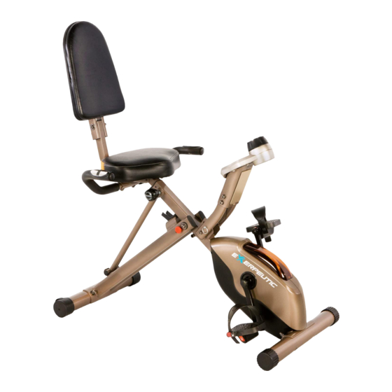
- Page 1 Recumbent Bike IMPORTANT: Read all instructions carefully before using this product. Retain this owner’s manual for future reference. The specifications of this product may vary from this photo, subject to change without notice. OWNER’S MANUAL 4153.8-052020...
- Page 2 PLEASE DO NOT RETURN THIS PRODUCT TO THE STORE. STOP. Contact customer service if you have any questions regarding assembly or proper operation of the machine. Email us at: Service@paradigmhw.com...
-
Page 3: Table Of Contents
TABLE OF CONTENTS SERVICE ------------------------------------------------------------------------------------------- LABEL PLACEMENTS -------------------------------------------------------------------------- IMPORTANT SAFETY GUIDELINES-------------------------------------------------------- OVERVIEW DRAWING ------------------------------------------------------------------------- PARTS LIST --------------------------------------------------------------------------------------- HARDWARE & TOOLS PACK ---------------------------------------------------------------- ASSEMBLY ---------------------------------------------------------------------------------------- COMPUTER --------------------------------------------------------------------------------------- STORAGE ----------------------------------------------------------------------------------------- ADJUSTMENTS ---------------------------------------------------------------------------------- TRANSPORTATION ---------- ------------------------------------------------------------------ MAINTENANCE & TROUBLESHOOTING ------------------------------------------------- WARRANTY --------------------------------------------------------------------------------------- PARTS REQUEST FORM ----------------------------------------------------------------------... -
Page 4: Service
SERVICE IMPORTANT: FOR NORTH AMERICA ONLY For damaged or defective product, questions, replacement parts or any other service support, please contact our customer service department by the below methods: For The Best Service, please Email: service@paradigmhw.com Response Time: 1-2 Business Days Emailing us with the information above will be the best method to receive a response during peak business hours Website:... -
Page 5: Label Placements
LABEL PLACEMENTS... -
Page 6: Important Safety Guidelines
IMPORTANT SAFETY GUIDELINES Read all instructions before using the Upright Bike. When using the bike, basic precautions should always be followed, including the following: WARNING - To reduce the risk of injury to persons: Make sure your equipment is correctly assembled before you use it. Be sure all screws, nuts, and bolts are tightened prior to use. - Page 7 IMPORTANT SAFETY GUIDELINES Do not use this equipment if you have any of the following conditions or ailments: Pregnancy Extreme obesity Middle ear infection Hiatus hernia or Ventral hernia Glaucoma, retinal detachment or conjunctivitis Use of anticoagulants including Aspirin in high doses. ...
-
Page 8: Overview Drawing
OVERVIEW DRAWING... -
Page 9: Parts List
PARTS LIST Description Description Rear Frame 30 Curved Washer Ø8.2xØ22.2 Front Frame 31 Front Stabilizer Rear Stabilizer 32 C-ring Ø10 Handlebar 33 Flat Washer Ø8.2xØ16.8 Seat Post 34 Nylon Nut M8 Seat 35 Magnet Bracket Left Pedal 36 Washer Ø6.2 7-1 Left Pedal Strap 37 Sensor Right Pedal... - Page 10 PARTS LIST Description Description 61 Flat Phillips Head Screw M6x10 88 Console 62 Oval End Cap 25x50 89 Screw 63 Round Phillips Head Screw 90 Hexagon Socket Bolt M8x15 M4x10 64 Plastic Washer 91 Hexagon Socket Bolt M8x35 65 C-ring Ø15 92 Oval End Cap 20x40 66 Square End Cap 93 Tension Cable...
-
Page 11: Hardware & Tools Pack
HARDWARE & TOOLS PACK... -
Page 12: Assembly
ASSEMBLY Tool: 13-15mm Wrench Rear Stabilizer (3) Transport Wheels Step 1 1a Frame Set Up: Pull apart the Front Frame (2) and the Rear Frame (1). Rest the Rear Frame Support Tube (67) into the curved bracket near the bottom of the Rear Frame (1). Align one of the two pin holes where the Front Frame (2) and Rear Frame (1) intersect and insert the Safety Pin (22) to lock the frames in place. - Page 13 ASSEMBLY Tools: 13-15mm Wrench 19mm Wrench WARNING: Install the Left Pedal (7) only with a counter-clockwise direction. Turning it in the wrong direction will damage the threads. The Right Pedal (8) should be installed only in the clockwise direction. Step 2 2a Attaching Pedal Straps Remove the Left Nylon Nut (112) and Right Nylon Nut (84) from the Left Pedal (7) and Right Pedal (8).
- Page 14 ASSEMBLY Tool: 5mm Allen Wrench with Phillips Screwdriver Step 3 Note: The Seat (6) has 2 sets of adjustment holes. It is recommended that users between 5’1” – 5’6” use the holes towards the rear of the Seat (6). It is recommended that users between 5’7” – 6’3”...
- Page 15 ASSEMBLY Step 4 4a Connection of wires: Connect the Connection Wires A (79) from the Seat Post (5) to the Connection Wires C (99) from the Front Frame (2) as shown in diagram AA-3. It may be easier to connect the wires with somebody there help you hold the Seat Post (5). 4b Installing the Seat Post to the Main Frame: Being careful not to pinch any of the wires, insert the Seat Post (5) into the Front Frame (2) and align the holes of the Seat Post (5) and Front Frame (2) to the height you desire.
- Page 16 ASSEMBLY Tools: 13-15mm Wrench Step 5 5a Installing the Rear Support Tube to the Seat Post: Align the bracket holes of the Rear Support Tube (15) to the the holes on the Seat Post (5) and secure the Rear Support Tube (15) to the Seat Post (5) with two Flat Washers (33), two Nylon Nuts (34), and two Carriage Bolts (106).
- Page 17 ASSEMBLY Tool: 5mm Allen Wrench with Phillips Screwdriver Step 6 6a Back Rest Installation: Then attach the Backrest (49) onto the Back Frame (9), and align the holes of the Backrest (49) to the Back Frame (9). Secure the Backrest (49) to the Back Frame (9) using four Hexagon Socket Bolts (101), four Spring Washers (102) and four Flat Washers (33).
- Page 18 ASSEMBLY Tool: 5mm Allen Wrench with Phillips Screwdriver 13-15mm Wrench 1 PC Step 7 7a Handlebar Installation: Attach the Handlebar (4) onto the Rear Support Tube (15) with two Curve Washers (30), two Spring Washers (102), two Hexagon Socket Bolts (101) and two Nylon Nuts (34).
- Page 19 ASSEMBLY Step 8 8a Console pre-installation: Insert the Console Bracket (69) onto the Console Support Tube (87), but do not secure. Remove the Console Cover (86). 8b Tension Cable Installation: Adjust the tension to the highest level on the Console (88) to give slack to the tension cable.
- Page 20 ASSEMBLY Step 9 9a Console installation: Connect the Upper Console Wire (96) to the Lower Console Wire (100). Refer to diagram AA-8. Connect the Pulse Extension Wires A (97) and Pulse Extension Wires B (99). Refer to diagram AA-8. Snap the Console Cover (86) back onto the Console Bracket (69).
-
Page 21: Computer
COMPUTER SPECIFICATIONS: TIME--------------------------------------------- 0:00~99:59MIN CALORIES------------------------------------- 0.0~999.9KCAL SPEED------------------------------------------ 0.0~999.9ML/H (KM/H) ODOMETER----------------------------------- 0~9999ML(KM) DISTANCE------------------------------------- 0.0~999.9ML(KM) PULSE (♥)-------------------------------------- 40~240BPM KEY FUNCTIONS: MODE: This key lets you select and lock on to any particular function you want. COMPUTER FUNCTIONS: TIME: Press the MODE key until the pointer locks onto TIME; this will display the amount of time the bike has been in use. -
Page 22: Storage
STORAGE For your convenience, the bike can be folded up for storage. Remove the Safety Pin (22) from the upper pin hole of the Rear Frame (1) and Pin (107) on Console Support Tube (87). Lift the Console Support Tube (87) upwards. Fold the Front Frame (2) and Rear frame (1) together. -
Page 23: Adjustments
ADJUSTMENTS Tension Control Knob (13) Adjusting the Tension Control Knob To Increase Tension: Turn the tension control knob (13) clockwise. To Decrease Tension: Turn the tension control knob (13) counterclockwise. Seat Height Adjustment Knob (14) Seat Post (5) Adjusting the Seat Height Loosen the Seat Height Adjustment Knob (14) by turning it counterclockwise. - Page 24 ADJUSTMENTS Adjusting the Backrest The Rear Supporting Tube (15) can be adjusted between 3 different positions: 1. Users between the height of 5’1” and 5’3” may want to use position 1, as shown in FIG. A. 2. Users between the height of 5’4” to 5’11” may want to use position 2 as shown in FIG. B. 3.
- Page 25 ADJUSTMENTS Adjusting the Pedal Strap L mark The Left Pedal Strap (7-1) has an L marked on the strap to signify left. See figure 1. Snap the slotted end of the Left Pedal Strap (7-1) onto the tab located on the inside edge of the Left Pedal (7) See figure 2 &...
-
Page 26: Transportation
TRANSPORTATION Transporting the Bike Hold the Handlebar (4) and tilt the bike backwards until the wheels on the Rear Stabilizer (3) make contact with the floor. Push or pull the unit to the desired location before gently lowering the Front Stabilizer (31) back down to the ground. -
Page 27: Maintenance & Troubleshooting
MAINTENANCE & TROUBLE SHOOTING MAINTENANCE Cleaning The bike can be cleaned with a soft clean damp cloth. Do not use abrasives or solvents on the plastic parts. Wipe your perspiration off the bike after each use. Be careful not to get excessive moisture on the computer display panel as this might cause an electronic failure. - Page 28 MAINTENANCE & TROUBLE SHOOTING 6. PROBLEM: High Tension on all settings a. SOLUTION: Remove the Console Cover (86) to verify that the Tension Control Knob (13) is properly connected to the Tension Cable (93). If not, un-hook the cables and reinstall the Tension Control Knob (13).
-
Page 29: Warranty
WARRANTY MANUFACTURER’S LIMITED WARRANTY Paradigm Health & Wellness warrants to the original purchaser that this product is free from defects in material and workmanship when used for the purpose intended, under the conditions that it has been installed and operated in accordance with Paradigm’s Owner’s Manual. -
Page 30: Parts Request Form
PARTS REQUEST FORM Paradigm Health & Wellness, Inc. EMAIL THIS FORM WITH YOUR RECEIPT OF PURCHASE TO Service@paradigmhw.com NAME:_____________________________________________________________ ________________________ ADDRESS:__________________________________________________________________________________ CITY:________________________ STATE:_____________ ZIP:_______________________________________ TELEPHONE: (Day)__________________________________________________________________________ (Night)________________________________________________________________________ SERIAL#:___________________________________________________________________________________ MODEL#:___________________________________________________________________________________ PURCHASE DATE:___________________________________________________________________________ PLACE OF PURCHASE:_______________________________________________________________________ PART # DESCRIPTION “YOUR ORDER WILL BE PROCESSED WITHIN 3 BUSINESS DAYS” * This form can also be faxed in Fax #: 626-810-2166...
Need help?
Do you have a question about the 525XLR and is the answer not in the manual?
Questions and answers