Table of Contents
Advertisement
Advertisement
Table of Contents

Related Manuals for Exerpeutic 900XL


Summary of Contents for Exerpeutic 900XL
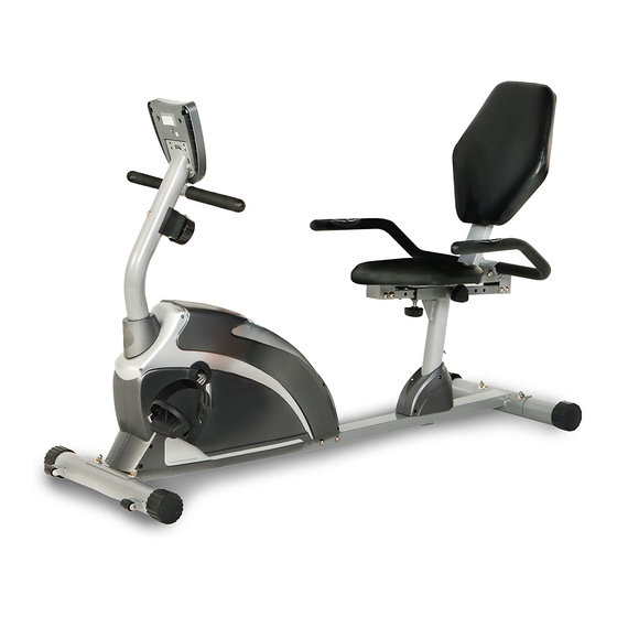
- Page 1 RECUMBENT BIKE IMPORTANT: Read all instructions carefully before using this product. Retain this owner’s manual for future reference. The specifications of this product may vary from this photo and, subject to change without notice. OWNER’S MANUAL 1111.9-100118...
- Page 2 PLEASE DO NOT RETURN THIS PRODUCT TO THE STORE. STOP. Contact customer service if you have any questions regarding assembly or proper operation of the machine. Email us at: Service@paradigmhw.com Or call us at: 1-844-641-7921 Hours: 8:00 am to 5:00 pm (PST) Monday thru Friday...
-
Page 3: Table Of Contents
TABLE OF CONTENTS SERVICE ------------------------------------------------------------------------------------ LABEL PLACEMENT --------------------------------------------------------------------- IMPORTANT SAFETY GUIDELINES ------------------------------------------------ OVERVIEW DRAWING ------------------------------------------------------------------ PARTS LIST -------------------------------------------------------------------------------- HARDWARE & TOOLS PACK -------------------------------------------------------- ASSEMBLY --------------------------------------------------------------------------------- CONSOLE---------------------------------------------------------------------------------- ADJUSTMENTS--------------------------------------------------------------------------- TROUBLESHOOTING & MAINTENANCE ----------------------------------------- WARRANTY ------------------------------------------------------------------------------- PARTS REQUEST FORM -------------------------------------------------------------... -
Page 4: Service
SERVICE IMPORTANT: FOR NORTH AMERICA ONLY For damaged or defective product, questions, replacement parts or any other service support, please contact our customer service department by the below methods: For The Best Service, please Email: service@paradigmhw.com Response Time: 1-2 Business Days Emailing us with the information above will be the best method to receive a response during peak business hours Website:... -
Page 5: Label Placement
LABEL PLACEMENT... -
Page 6: Important Safety Guidelines
IMPORTANT SAFETY GUIDELINES Read all guidelines before using this machine. When using this machine, basic precautions should always be followed, including the following: WARNING - To reduce the risk of injury to persons: Make sure your equipment is correctly assembled before you use it. Be sure all screws, nuts, and bolts are tightened prior to use. - Page 7 IMPORTANT SAFETY GUIDELINES Do not use this equipment if you have any of the following conditions or ailments: Pregnancy Extreme obesity Middle ear infection Hiatus hernia or Ventral hernia Glaucoma, retinal detachment or conjunctivitis Use of anticoagulants including Aspirin in high doses.
-
Page 8: Overview Drawing
OVERVIEW DRAWING... -
Page 9: Parts List
PARTS LIST Description Description Back and Seat Support Bracket Bolt M8x18 53x23x2.0 Front Stabilizer Ø60x1.5x580 Locknut M6 Rear Main Frame Bolt M8x70 Rear Stabilizer Ø60x1.5x580 Spring Front Main Frame 80x40x2 Cap Nut M8 Front Handlebar Post Ø50x1.5 Left Cover Seat Cushion Right Cover Back Cushion Screw ST4.2x25... - Page 10 PARTS LIST Description Description 54 Bushing Bolt M8x45 55 Middle Section Hand Pulse Bolt M6x48 Sensor Wire 56 Idle Wheel Axle Sleeve II 57 Rear Stabilizer End Cap Ø60 Washer 7/8" 58 Washer Ø6 Front Handlebar Post Cover 59 Right Foot Pedal YH-30X Right Rear Main Frame Cover 60 Left Foot Pedal YH-30X Left Rear Main Frame Cover...
-
Page 11: Hardware & Tools Pack
HARDWARE & TOOLS PACK... -
Page 12: Assembly
ASSEMBLY Tool: 6mm Allen Wrench Step 1 1a. Removing the Hardware from the Rear Main Frame - Remove two Bolts (49), four Bolts (23), and six Washers (24) from the Rear Main Frame (3). Remove bolts with the 6mm Allen Wrench provided. 1b. -
Page 13: Rear Main Frame (
ASSEMBLY Tool: Multi Hex Tool with Phillips Screwdriver STEP 2 2a. Installing the Front Stabilizer - Position the Front Stabilizer (2) in front of the Front Main Frame (5) and align bolt holes. Attach the Front Stabilizer (2) onto the front curve of the Front Main Frame (5) with two Bolts (30), two Curve Washers (25), and two Cap Nuts (32). - Page 14 ASSEMBLY Tool: 6 mm Allen Wrench MUST TIGHTEN IN Multi Hex Tool with Phillips SEQUENCE: Screwdriver A,B,C,D. STEP 3 3a. Removing The Hardware From The Front Post –Remove four Bolts (23) and four Curve Washers (25) from the Front Main Frame (5). Slide the Front Handlebar Post Cover (74) up to the Front Handlebar Post (6).Insert the Tension Cable (40) through into the bottom hole of Front Handlebar Post (6) and pull it out from the square hole of Front Handlebar Post (6).
- Page 15 ASSEMBLY Tool: Multi Hex Tool with Phillips Screwdriver STEP 4 The Cranks, Foot Pedals, Pedal Shafts and Pedal Straps are marked “R” for Note: Right and “L” for Left. 4a. Installing the Left Pedal: Insert the threaded shaft of the Left Foot Pedal (60) into the threaded hole on the Left Crank (46).
- Page 16 ASSEMBLY Tool: Multi Hex Tool with Phillips Screwdriver 6mm Allen Wrench STEP 5 5a. Removing Hardware- Remove eight Bolts (23) and eight Washers (24) from the Back/Seat Support Bracket (1) and Seat Sliding Tube (15). Remove bolts with the 6mm Allen Wrench provided.
- Page 17 ASSEMBLY Tool: Multi Hex Tool with Phillips Screwdriver STEP 6 6a. Removing Hardware- Remove eight Bolts (23) and eight Washers (24) from the Back/Seat Support Bracket (1) and Seat Sliding Tube (15). Remove bolts with the 6mm Allen Wrench provided. 6b.
-
Page 18: Back Cushion 1
ASSEMBLY Tool: Multi Hex Tool with Phillips Screwdriver 7a. Removing Hardware - Remove eight Bolts (21) and eight Washers (58) from the back of the Seat and Back Cushions (7, 8). Remove bolts with the Multi Hex Tool with Phillips Screwdriver provided. -
Page 19: Console
CONSOLE OPERATING THE COMPUTER SPECIFICATIONS: TIME --------------------------------------------------- 0:00-99:59 MIN: SEC SPEED ------------------------------------------------ 0.0-999.9 MPH DIST (DISTANCE) ---------------------------------- 0.0-999.9 MILE CAL (CALORIES) ----------------------------------- 0.0-999.9 KCAL ODO (ODOMETER) -------------------------------- 0.0-999.9 MILE (PULSE) ------------------------------------------ 40-240 BEATS/MIN BUTTON FUNCTIONS: MODE: Press MODE button to select each function of computer. Press and hold MODE button for 3 seconds, all data values will clear to zero except the ODO (ODOMETER) data values. - Page 20 CONSOLE SPEED: Press MODE button until the screen displays SPEED; the computer will display the current training speed. DIST (DISTANCE): Press MODE button until the screen displays DIST; the computer will display the accumulative distance traveled during workout. When you start to exercise, distance starts counting up from 0.0 to 999.9 miles per 0.1 mile increment.
- Page 21 CONSOLE HOW TO INSTALL THE BATTERIES: Remove the battery cover at the rear of computer. Place two "SIZE-AA" batteries into the battery housing. Insure batteries are correctly positioned and battery springs are in proper contact with batteries. Re-install the battery cover. If the display is illegible or only partial legible, remove batteries and wait 15 seconds before reinstalling.
-
Page 22: Adjustments
ADJUSTMENTS Adjusting the Tension Control Knob To increase the load, turn the tension control knob in a clockwise direction. To decrease the load, turn the tension control knob in a counterclockwise direction. Tension Control Knob Adjusting the Rear Stabilizer End Cap Turn the rear stabilizer end cap on the rear stabilizer as needed to level the elliptical trainer Rear Stabilizer End Cap... -
Page 23: Troubleshooting & Maintenance
TROUBLESHOOTING & MAINTENANCE Cleaning The recumbent bike can be cleaned with a soft cloth and mild detergent. Do not use abrasives or solvents on plastic parts. Please wipe your perspiration off the recumbent bike after each use. Be careful not get excessive moisture on the computer display panel as this might cause an electrical hazard or electronics to fail. -
Page 24: Warranty
WARRANTY MANUFACTURER’S LIMITED WARRANTY Paradigm Health & Wellness warrants to the original purchaser that this product is free from defects in material and workmanship when used for the purpose intended, under the conditions that it has been installed and operated in accordance with Paradigm’s Owner’s Manual. -
Page 25: Parts Request Form
PARTS REQUEST FORM Paradigm Health & Wellness, Inc. EMAIL THIS FORM WITH YOUR RECEIPT OF PURCHASE TO Service@paradigmhw.com NAME:_____________________________________________________________________________________ ADDRESS:__________________________________________________________________________________ CITY:________________________ STATE:_____________ ZIP:_______________________________________ TELEPHONE: (Day)______________________________________________________________________ (Night)_____________________________________________________________________ SERIAL#:___________________________________________________________________________________ MODEL#:___________________________________________________________________________________ PURCHASE DATE:___________________________________________________________________________ PLACE OF PURCHASE:_______________________________________________________________________ PART # DESCRIPTION “YOUR ORDER WILL BE PROCESSED WITHIN 3 BUSINESS DAYS” This form can also be faxed to #: 626-810-2166...
Need help?
Do you have a question about the 900XL and is the answer not in the manual?
Questions and answers
where are batteries located
I don’t know which model I have all it says is exepeuric with no model number
The model number of the Exerpeutic 900XL is 1111.
This answer is automatically generated
@Dale Culbertson Please help, I've had it for years collecting dust