Table of Contents
Advertisement
Advertisement
Table of Contents

Related Manuals for Exerpeutic ExerWorK Series


Summary of Contents for Exerpeutic ExerWorK Series
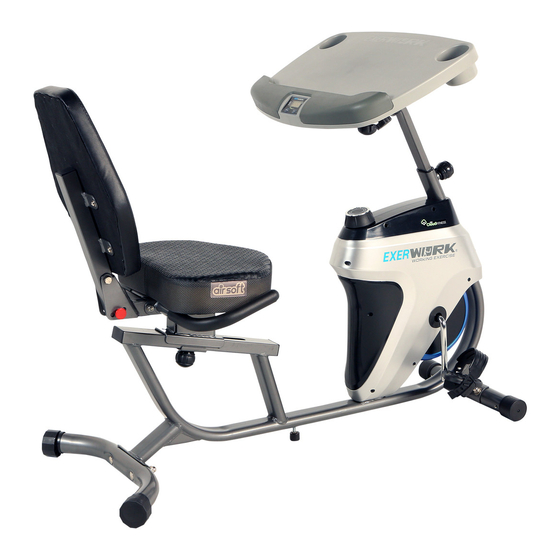
- Page 1 Desk Recumbent Bike IMPORTANT: Read all instructions carefully before using this product. Retain this owner’s manual for future reference. The specifications of this product may vary from this photo, subject to change without notice. OWNER’S MANUAL 7170.2-032519...
- Page 2 PLEASE DO NOT RETURN THIS PRODUCT TO THE STORE. STOP. Contact customer service if you have any questions regarding assembly or proper operation of the machine. Email us at: Service@paradigmhw.com Or call us at: 1-844-641-7921 Hours: 8:00 am to 5:00 pm (PST) Monday thru Friday...
-
Page 3: Table Of Contents
TABLE OF CONTENTS SERVICE------------------------------------------------------------------------------- LABEL PLACEMENT---------------------------------------------------------------- IMPORTANT SAFETY GUIDELINES------------------------------------------- OVERVIEW DRAWING------------------------------------------------------------- PARTS LIST--------------------------------------------------------------------------- HARDWARE & TOOLS PACK--------------------------------------------------- ASSEMBLY---------------------------------------------------------------------------- CONSOLE ---------------------------------------------------------------------------- OPERATIONS & ADJUSTMENTS---------------------------------------------- BATTERY INSTALLATION-------------------------------------------------------- TRANSPORTION-------------------------------------------------------------------- MAINTENANCE & TROUBLESHOOTING---------------------------------- WARRANTY--------------------------------------------------------------------------- PART REQUEST FORM-----------------------------------------------------------... -
Page 4: Service
SERVICE IMPORTANT: FOR NORTH AMERICA ONLY For damaged or defective product, questions, replacement parts or any other service support, please contact our customer service department by the below methods: For The Best Service, please Email: service@paradigmhw.com Response Time: 1-2 Business Days Emailing us with the information above will be the best method to receive a response during peak business hours Website:... -
Page 5: Label Placement
LABEL PLACEMENT... -
Page 6: Important Safety Guidelines
IMPORTANT SAFETY GUIDELINES Basic precautions should always be followed, including the following safety guidelines when using this desk bike. Read all of the guidelines before using this desk bike. Before exercising and to avoid injuring your muscles, it is highly recommended that you perform warm-up exercises for each muscle group. - Page 7 IMPORTANT SAFETY GUIDELINES Do not use this equipment if you have any of the following conditions or ailments: Pregnancy Extreme obesity Middle ear infection Hiatus hernia or Ventral hernia Glaucoma, retinal detachment or conjunctivitis Use of anticoagulants including Aspirin in high doses.
-
Page 8: Overview Drawing
OVERVIEW DRAWING... - Page 9 OVERVIEW DRAWING...
-
Page 10: Parts List
PARTS LIST Description Description 1 Main Frame 32 Sensor Wire W=650mm 2 Front Stabilizer 33 Left Pedal 3 Rear Stabilizer 34 Left Pedal Strap 4 Left Handlebar 35 Right Pedal 5 Right Handlebar 36 Right Pedal Strap 6 Seat Bracket 37 Carraige Bolt M10*65 38 Curved WasherФ10 7 Backrest Frame... -
Page 11: Sqaure End Cap
PARTS LIST No. Description Description 64 Hex Nut 7/8” 78 Hex Bolt M8*50 65 Flat Washer Ф23 79 Sqaure End Cap 66 Bearing Nut 80 Fly Wheel 67 Ball Bearing 81 Flange Nut M10*1.0*6 68 Bearing Cup 82 Eye Bolt M6*36 69 Bearing Nut 83 U-Bracket 70 Flat Washer Ф24... -
Page 12: Hardware & Tools Pack
HARDWARE & TOOLS PACK... -
Page 13: Assembly
ASSEMBLY TOOLS Open-Ended Flat Wrench S10, S13, S17, S19 1PC Step 1 1A. Front Stabilizer Installation: Lift up the front of the Main Frame (1), and attach the Front Stabilizer (2) onto the front curve of the Main Frame (1) with two Carriage Bolts (37), two Curve Washers (38), two Spring Washers (39), and two Cap Nuts (40). - Page 14 ASSEMBLY The Cranks, Pedal Straps, Pedal Shafts, and Foot Pedals are marked “R” for Right and “L” for Left. TOOLS Multi Hex Tool With Phillips Screwdriver Step 2 2A. Pedal Strap installation: Install the Left Pedal Strap (34) onto the Left Pedal (33).
- Page 15 ASSEMBLY TOOLS 6mm Allen Wrench Multi Hex Tool With Phillips Screwdriver Step 3 3A. Handlebar Installation: Attach the Left and Right Handlebars (4,5) onto the Seat Bracket (6). Using two Hex Bolts (17), four Washers (18) and two Nylon Nuts (19). Then tighten with the 6mm Allen Wrench and the Multi Hex Tool with Phillips Screwdriver provided.
- Page 16 ASSEMBLY TOOLS Multi Hex Tool S10, S13, S14, S15 1PC STEP 4 4A. Seat Installation : Remove the four Screws (59), four Spring Washers (58) and the four Flat Washers (57) from the Seat (53). Align the holes of the Seat (53) to the holes of the Seat Bracket (6).
- Page 17 ASSEMBLY TOOLS 6mm Allen Wrench Multi Hex Tool S10, S13, S14, S15 1PC STEP 6 6A. Backrest Frame Installation: Insert the Backrest Frame (7) onto the Seat Bracket (6), and align the hole tighten with one Hex Bolt (17), two Flat Washers (18) and one Nylon Nut (19). Tighten the hardware with 6mm Allen Wrench and the Multi Hex Tool with Phillips Screwdriver provided.
- Page 18 ASSEMBLY TOOLS 6mm Allen Wrench Multi Hex Tool S10, S13, S14, S15 1PC STEP 7 7A. Desk Installation: Remove one Flat Washer (18) and one Hex Bolt (20) from the Front Post (8). Insert the Front Post (8) onto the bracket of the Desk (13), align the hole and tighten with two Hex Bolts (17), four Flat Washers (18), two Nylon Nuts (19), one Flat Washer (18) and one Hex Bolt (20) that were previously removed.
- Page 19 ASSEMBLY Fig. B STEP 8 8A. Connecting the Console Wire (15) with the Sensor Wire (32): Connecting the Console Wire (15) from the Front Post (8) with the Sensor Wire (32) from the Main Frame (1). 8B. Front Post Installation: Insert the Front Post (8) onto the Main Frame (1) and tighten with one Spring Knob (30).
-
Page 20: Console
CONSOLE SPECIFICATIONS: TIME -----------------------------0:00-99:59 MIN:SEC SPEED --------------------------0.0-99.9 ML/H DISTANCE ---------------------0.0-999.9 ML CALORIE -----------------------0.0-9999 KCAL CONSOLE FUNTIONS: MODE: Press the “MODE” button to select between, SCAN,SPEED,DISTANCE,TIME, and CALORIES. AUTO ON/OFF: The console will automatically turn on when pedaling begins. The console will automatically turn off after 4 minutes of inactivity. -
Page 21: Rear Stabilizer End Cap
ADJUSTMENT Rear Stabilizer (3) Adjustable Leveler (45) Rear Stabilizer End Cap (43) ADJUSTING THE REAR STABILIZER END CAP: Adjust the Rear Stabilizer End Caps (43) on the Rear Stabilizer (3) as needed to level the recumbent bike. ADJUST THE ADJUSTABLE LEVELER: If the bike is bouncing when in use, turn the Adjustable Leveler (45) so that is making contact with the floor. - Page 22 ADJUSTMENT ADJUSTING THE DESK HEIGHT: Loosen the Spring Knob (30) and lift up or down the Desk (13) to desired position. ADJUSTING THE BACKREST: Insert the Pin (56) into hole on the Seat Bracket (6) to adjust the Backrest (54) to desired postition.
- Page 23 ADJUSTMENT ADJUSTING THE DESK RANGE: 1. Loosen the Left and Right Adjustable Post Knobs (24) by turning them COUNTER- CLOCKWISE. 2. Shift the Desk (13) forward or backwards to the desired position. 3. Tighten the Left and Right Adjustable Post Knobs (24) by turning it CLOCKWISE to lock the Desk(13) in place.
-
Page 24: Operations & Adjustments
OPERATIONS & ADJUSTMENTS INCREASE DECREASE ADJUSTING THE TENSION CONTROL KNOB To increase the resistance, turn the Tension Control Knob (61) in a CLOCKWISE direction. To decrease the resistance, turn the Tension Control Knob (61) in a COUNTERCLOCKWISE direction. -
Page 25: Battery Installation
BATTERY INSTALLATION HOW TO INSTALL THE BATTERIES: 1. Remove the battery cover on the back of the computer. 2. Place two "SIZE-AAA" batteries into the battery housing. 3. Ensure that the batteries are correctly positioned and that the battery springs are in proper contact with batteries. -
Page 26: Transportion
TRANSPORTATION TRANSPORTING THE BIKE 1. Hold onto the Rear Stabilizer (3) and tilt the bike onto to the wheels of the Front Stabilizer (2). 2. Carefully move the bike to the desired location. 3. Gently lower the bike until the Rear Stabilizer (3) touches the floor. NOTE* Please remove all items from the desktop before making any adjustments. -
Page 27: Maintenance & Troubleshooting
TROUBLE SHOOTING & MAINTENANCE TROUBLE SHOOTING PROBLEM: The recumbent bike wobbles when in use. 1)SOLUTION: Turn the Rear Stabilizer End Caps (43) on the Rear Stabilizer (3) or Adjustable Leveler (45) on the bottom of the rear Main Frame (1) as needed to level the recumbent bike. -
Page 28: Warranty
WARRANTY MANUFACTURER’S LIMITED WARRANTY Paradigm Health & Wellness warrants to the original purchaser that this product is free from defects in material and workmanship when used for the purpose intended, under the conditions that it has been installed and operated in accordance with Paradigm’s Owner’s Manual. -
Page 29: Part Request Form
PARTS REQUEST FORM Paradigm Health & Wellness, Inc. EMAIL THIS FORM WITH YOUR RECEIPT OF PURCHASE TO Service@paradigmhw.com NAME:______________________________________________________________________ ADDRESS:__________________________________________________________________ CITY:________________________ STATE:_____________ ZIP:________________________ TELEPHONE: (Day)_______________________________________________________ (Night)______________________________________________________ SERIAL#:____________________________________________________________________ MODEL#:____________________________________________________________________ PURCHASE DATE:____________________________________________________________ PLACE OF PURCHASE:_______________________________________________________ PART # DESCRIPTION “YOUR ORDER WILL BE PROCESSED WITHIN 3 BUSINESS DAYS” *This form can also be faxed to #: 626-810-2166...
Need help?
Do you have a question about the ExerWorK Series and is the answer not in the manual?
Questions and answers