
Related Manuals for Avalue Technology ECM-APL2-A


Summary of Contents for Avalue Technology ECM-APL2-A
- Page 1 ECM-APL2 Intel Apollo Lake processor 3.5 Micro Module User’s Manual Ed – 30 July 2020 Part No. E2047393405R...
- Page 2 Disclaimer Avalue Technology Inc. reserves the right to make changes, without notice, to any product, including circuits and/or software described or contained in this manual in order to improve design and/or performance. Avalue Technology assumes no responsibility or liability for the...
- Page 3 Applications that are described in this manual are for illustration purposes only. Avalue Technology Inc. makes no representation or warranty that such application will be suitable for the specified use without further testing or modification.
- Page 4 ECM-APL2 User’s Manual Product Warranty Avalue warrants to you, the original purchaser, that each of its products will be free from defects in materials and workmanship for two years from the date of purchase. This warranty does not apply to any products which have been repaired or altered by persons other than repair personnel authorized by Avalue, or which have been subject to misuse, abuse, accident or improper installation.
-
Page 5: Table Of Contents
User’s Manual Content Getting Started ......................8 Safety Precautions ....................8 Packing List ....................... 8 Document Amendment History ................. 9 Manual Objectives ....................10 System Specifications ..................... 11 Architecture Overview—Block Diagram ..............13 Hardware Configuration ................... 14 Product Overview ....................15 Jumper and Connector List .................. - Page 6 ECM-APL2 User’s Manual In Case of Problems ....................31 BIOS setup ......................32 3.6.1 Main Menu ............................32 3.6.1.1 System Language ........................33 3.6.1.2 System Date .......................... 33 3.6.1.3 System Time .......................... 33 3.6.2 Advanced Menu ..........................33 3.6.2.1 Trusted Computing ........................ 34 3.6.2.2 APCI Settings ........................
- Page 7 User’s Manual 3.6.6 Save and exit ..........................58 3.6.6.1 Save Changes and Reset ...................... 58 3.6.6.2 Discard Changes and Reset ....................58 3.6.6.3 Restore Defaults ........................58 3.6.6.4 Launch EFI Shell from filesystem device ................58 4. Drivers Installation....................... 59 Install Chipset Driver ....................
-
Page 8: Getting Started
ECM-APL2 User’s Manual Getting Started 1.1 Safety Precautions Warning! Always completely disconnect the power cord from your chassis whenever you work with the hardware. Do not make connections while the power is on. Sensitive electronic components can be damaged by sudden power surges. -
Page 9: Document Amendment History
User’s Manual 1.3 Document Amendment History Revision Date Comment August 2017 Avalue Initial Release November 2019 Avalue Update System Specifications Update Architecture Overview—Block June 2020 Avalue Diagram July 2020 Avalue Update Packing List ECM-APL2 User’s Manual... -
Page 10: Manual Objectives
ECM-APL2 User’s Manual 1.4 Manual Objectives This manual describes in details Avalue Technology ECM-APL2 Single Board. We have tried to include as much information as possible but we have not duplicated information that is provided in the standard IBM Technical References, unless it proved to be necessary to aid in the understanding of this board. -
Page 11: System Specifications
User’s Manual 1.5 System Specifications System Onboard Intel® Pentium® /Celeron® /Atom™ SoC BGA Processor (Apollo Lake Platform)- (with CPU Bottom Mounted) BIOS AMI BIOS, 128 Mbit SPI Flash ROM System Chipset Apollo SoC integrated I/O Chip EC(IT8528VG) One 204-pin DDR3L SODIMM Socket, Supports Up to 8GB DDR3L 1866MTs System Memory SDRAM (Non-ECC) mSATA supported from MiniPCIe... - Page 12 ECM-APL2 User’s Manual CPU_FAN1 4pin 2.5mm wafer header Buzzer With Pin header CMOS Battery CR2032 Power On AX/ATX selectable by jumper 1 x RS232/422/485 (selectable by BIOS, w/ Auto Flow) Rear I/O Connectors 4 x USB3.0 2 x RJ-45 HDMI 2 x HDMI Stack LED indicator for power/HDD Mechanical &...
-
Page 13: Architecture Overview-Block Diagram
User’s Manual 1.6 Architecture Overview—Block Diagram The following block diagram shows the architecture and main components of ECM-APL2. ECM-APL2 User’s Manual 13... -
Page 14: Hardware Configuration
ECM-APL2 User’s Manual 2. Hardware Configuration 14 ECM-APL2 User’s Manual... -
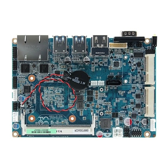
Page 15: Product Overview
User’s Manual 2.1 Product Overview ECM-APL2 User’s Manual 15... -
Page 16: Jumper And Connector List
ECM-APL2 User’s Manual 2.2 Jumper and Connector List You can configure your board to match the needs of your application by setting jumpers. A jumper is the simplest kind of electric switch. It consists of two metal pins and a small metal clip (often protected by a plastic cover) that slides over the pins to connect them. - Page 17 User’s Manual D-sub 9-pin, male Note:COM1 support COM1 Serial port 1 connector RS422/485 by BIOS setting JCOM2 Serial port 2 connector 5 x 2 header, pitch 2.00 mm JDIO1 General purpose I/O connector 6 x 2 header, pitch 2.00 mm JFP1 Miscellaneous setting connector 5 x 2 header, pitch 2.00 mm...
-
Page 18: Setting Jumpers & Connectors
ECM-APL2 User’s Manual 2.3 Setting Jumpers & Connectors 2.3.1 AT/ATX Input power select (JAT1) * Default 2.3.2 Clear CMOS (JBAT1) Protect* Clear CMOS * Default 18 ECM-APL2 User’s Manual... -
Page 19: Serial Port 1/2 Pin9 Signal Select (Jri1/2)
User’s Manual 2.3.3 Serial port 1/2 pin9 signal select (JRI1/2) Ring* JRI1 JRI2 +12V * Default Serial port 1/2 – RS232/422/485 mode select (JCOM_SEL1/2) 2.3.4 JCOM_SEL1 RS-232* JCOM_SEL2 RS422/485 * Default ECM-APL2 User’s Manual 19... -
Page 20: Cpu Fan Connector (Cpu_Fan1)
ECM-APL2 User’s Manual 2.3.5 CPU fan connector (CPU_FAN1) Signal +12V EC_TACH0 FAN_PWM0 2.3.6 Serial port 2 connector (JCOM2) Signal PIN PIN Signal COM_RI#_2_2 COM_CTS#_2 COM_RTS#_2 COM_DSR#_2 COM2-4 COM2-3 COM2-2 COM2-1 20 ECM-APL2 User’s Manual... -
Page 21: General Purpose I/O Connector (Jdio1)
User’s Manual 2.3.7 General purpose I/O connector (JDIO1) Signal PIN PIN Signal DIO_GP20 DIO_GP10 DIO_GP21 DIO_GP11 DIO_GP22 DIO_GP12 DIO_GP23 DIO_GP13 SMB_SCL_S0 SMB_SDA_S0 2.3.8 SATA Power header (SATA_PWR1) Signal ECM-APL2 User’s Manual 21... -
Page 22: Power Connector (Pwr1)
ECM-APL2 User’s Manual 2.3.9 Power connector (PWR1) Signal PIN PIN Signal +26V_VIN_VIN +26V_VIN_VIN 2.3.10 Low pin count interface (JLPC1) Signal PIN PIN Signal LPC_AD0 +3.3V LPC_AD1 PLT_RST_BUF# LPC_AD2 LPC_FRAME# LPC_AD3 LPC_PORT80_CLK LPC_SERIRQ 22 ECM-APL2 User’s Manual... -
Page 23: Usb Connector 1 (Jusb1)
User’s Manual 2.3.11 USB connector 1 (JUSB1) Signal +5VSB USB_R_DN7 USB_R_DP7 2.3.12 USB connector 2 (JUSB2) Signal +5VSB USB_R_DN5 USB_R_DP5 ECM-APL2 User’s Manual 23... -
Page 24: Ec Debug Connector (Jec_Rom1)
ECM-APL2 User’s Manual 2.3.13 EC Debug connector (JEC_ROM1) Signal EC_SMCLK_DEBUG EC_SMDAT_DEBUG 2.3.14 Miscellaneous setting connector (JFP1) Signal PIN PIN Signal PWR_BTN_IN_EC# PMU_RSTBTN# FP_PWR_LED+ PWR_LED# HDD_LED# CASE_OPEN# 24 ECM-APL2 User’s Manual... -
Page 25: Bios Spi Header (Bios_Spi1)
User’s Manual 2.3.15 BIOS SPI header (BIOS_SPI1) Signal PIN PIN Signal +1.8VSB SPI_CS#0 CPI_CLK SPI_MISO SPI_MOSI SPI_HOLD# SPI_WP# 2.3.16 PC Buzzer connector (JBZ1) Signal SOC_SPKR_R ECM-APL2 User’s Manual 25... -
Page 26: Battery Connector (Bt1)
ECM-APL2 User’s Manual 2.3.17 Battery connector (BT1) Signal +RTCBATT 2.3.18 Audio connector (JAUDIO1) Signal PIN PIN Signal FRONT-R-OUT FRONT-L-OUT HD_AGND HD_AGND LINE1-R-IN LINE1-L-IN MIC1-R-IN MIC1-L-IN FRONT-JD LINE1-JD MIC1-JD HD_AGND 2.3.18.1 Signal Description – Audio connector (JAUDIO1) Signal Signal Description LINE1-JD AUDIO IN (LINE_RIN/LIN)sense pin FRONT-JD AUDIO Out(ROUT/LOUT) sense pin... -
Page 27: Vga Connector (Jvga1)
User’s Manual 2.3.19 VGA connector (JVGA1) Signal PIN PIN Signal VGA_RED VGA_GREEN VGA_BLUE VGA_DDCDAT VGA_HSYNC_R VGA_VSYNC_R VGA_DDCCLK ECM-APL2 User’s Manual 27... -
Page 28: Bios Setup
ECM-APL2 User’s Manual 3.BIOS Setup 28 ECM-APL2 User’s Manual... -
Page 29: Introduction
User’s Manual 3.1 Introduction The BIOS setup program allows users to modify the basic system configuration. In this following chapter will describe how to access the BIOS setup program and the configuration options that may be changed. 3.2 Starting Setup AMI BIOS™... -
Page 30: Using Setup
ECM-APL2 User’s Manual 3.3 Using Setup In general, you use the arrow keys to highlight items, press <Enter> to select, use the PageUp and PageDown keys to change entries, press <F1> for help and press <Esc> to quit. The following table provides more detail about how to navigate in the Setup program using the keyboard. -
Page 31: Getting Help
User’s Manual 3.4 Getting Help Press F1 to pop up a small help window that describes the appropriate keys to use and the possible selections for the highlighted item. To exit the Help Window press <Esc> or <Enter> key. 3.5 In Case of Problems If, after making and saving system changes with Setup, you discover that your computer no longer is able to boot, the AMI BIOS supports an override to the NVRAM settings which resets your system to its defaults. -
Page 32: Bios Setup
ECM-APL2 User’s Manual 3.6 BIOS setup Once you enter the Aptio Setup Utility, the Main Menu will appear on the screen. The Main Menu allows you to select from several setup functions and exit choices. Use the arrow keys to select among the items and press <Enter> to accept and enter the sub-menu. 3.6.1 Main Menu This section allows you to record some basic hardware configurations in your computer and set the system clock. -
Page 33: System Language
User’s Manual 3.6.1.1 System Language This option allows choosing the system default language. 3.6.1.2 System Date Use the system date option to set the system date. Manually enter the day, month and year. 3.6.1.3 System Time Use the system time option to set the system time. Manually enter the hours, minutes and seconds. -
Page 34: Trusted Computing
ECM-APL2 User’s Manual 3.6.2.1 Trusted Computing Item Options Description Enables or Disables BIOS support for security Disable, device. O.S. will not show Security Device. TCG Security Device Support Enable[Default] EFI protocol and INT1A interface will not be available. Select to Tell O.S. to support PPI Spec Version 1.2[Default] Physical Presence Spec Version 1.2 or 1.3. -
Page 35: It8528 Super Io Configuration
User’s Manual Item Options Description Enables or Disables System ability to Disabled Hibernate (OS/S4 Sleep State). This Enable Hibernation Enabled[Default] option may be not effective with some Select the highest ACPI sleep state the Suspend Disabled, ACPI Sleep State system will enter when the SUSPEND S3 (Suspend to RAM) [Default] button is pressed. -
Page 36: Serial Port 1 Configuration
ECM-APL2 User’s Manual Item Description Serial Port 1 Configuration Set Parameters of Serial Port 1 (COMA). Serial Port 2 Configuration Set Parameters of Serial Port 2 (COMB). 3.6.2.3.1 Serial Port 1 Configuration Item Option Description Disabled Serial Port Enable or Disable Serial Port (COM). Enabled[Default] UART 232[Default] UART 232 422 485... -
Page 37: Serial Port 2 Configuration
User’s Manual 3.6.2.3.2 Serial Port 2 Configuration Item Option Description Disabled Serial Port Enable or Disable Serial Port (COM). Enabled[Default] UART 232[Default] Change the Serial Port as UART 232 422 485 UART 422 RS232/422/485. UART 485 3.6.2.4 H/W Monitor ECM-APL2 User’s Manual 37... -
Page 38: S5 Rtc Wake Settings
ECM-APL2 User’s Manual Item Options Description Enabled, Smart Fan Function Enables or Disables Smart Fan. Disabled[Default] 3.6.2.5 S5 RTC Wake Settings Item Options Description Enable or disable System wake on alarm event. Select Disabled[Default], Fixed Time, system will wake on the hr::min::sec specified. Wake system from S5 Fixed Time Select Dynamic Time, System will wake on the current time... -
Page 39: Legacy Console Redirection Settings
User’s Manual Item Options Description Disabled[Default], Console Redirection Console Redirection Enable or Disable. Enabled 3.6.2.6.1 Legacy Console Redirection Settings Item Option Description Select a COM port to display redirection of Legacy Serial Redirection Port COM0[Default] Legacy OS and Legacy OPROM Messages. 3.6.2.7 CPU Configuration Use the CPU configuration menu to view detailed CPU specification and configure the CPU. -
Page 40: Socket 0 Cpu Information
ECM-APL2 User’s Manual Item Options Description Disabled[Default] Number of cores to enable in each processor Active Processor Cores Enabled package. When enabled, a VMM can utilize the additional Disabled Intel Virtualization Technology hardware capabilities provided by Vanderpool Enabled[Default] Technology. Disabled[Default] VT-d Enable/Disable CPU VT-d. -
Page 41: Cpu Power Management Configuration
User’s Manual 3.6.2.7.2 CPU Power Management Configuration Item Option Description Disabled EIST Enable/Disable Intel SpeedStep. Enabled[Default] Disabled Turbo Mode Turbo Mode. Enabled[Default] 3.6.2.8 Network Stack Configuration Item Options Description Disabled[Default] Network Stack Enable/Disable UEFI Network Stack. Enabled ECM-APL2 User’s Manual 41... -
Page 42: Csm Configuration
ECM-APL2 User’s Manual 3.6.2.9 CSM Configuration Item Options Description Disabled[Default] CSM Support Enable/Disable CSM Support. Enabled 3.6.2.10 NVMe Configuration 42 ECM-APL2 User’s Manual... -
Page 43: Usb Configuration
User’s Manual 3.6.2.11 USB Configuration The USB Configuration menu helps read USB information and configures USB settings. Item Options Description Enables Legacy USB support. AUTO option Enabled[Default] disables legacy support if no USB devices are Legacy USB Support Disabled connected. DISABLE option will keep USB Auto devices available only for EFI applications. -
Page 44: Security Configuration
ECM-APL2 User’s Manual 3.6.2.12 Security Configuration Item Options Description Enabled TXE HMRFPO TXE HMRFPO. Disabled[Default] Enabled[Default] TXE EOP Message Send EOP Message Before Enter OS. Disabled 3.6.3 Chipset 44 ECM-APL2 User’s Manual... -
Page 45: North Bridge
User’s Manual 3.6.3.1 North Bridge Item Option Description 2 GB[Default] 2.25 GB Max TOLUD Maximum Value of TOLUD. 2.5 GB 2.75 GB Enable/Disable above 4GB Memory Enabled MappedIO BIOS assignment This is disabled Above 4GB MMIO BIOS assignment Disabled[Default] automatically when Aperture Size is set to 2048MB. -
Page 46: South Bridge
ECM-APL2 User’s Manual 3.6.3.2 South Bridge Item Option Description Quiet Serial IRQ Mode Configure Serial IRQ Mode. Continuous[Default] Windows[Default] OS Selection Android Select the target OS. Intel Linux 46 ECM-APL2 User’s Manual... -
Page 47: Uncore Configuration
User’s Manual 3.6.3.3 Uncore Configuration Item Option Description Enable[Default] Enable GOP Driver will unload VBIOS ; GOP Driver Disable Dsiable it will load VBIOS. 144 MHz 288 MHz Select the highest Cd Clock frequency Cd Clock Frequency 384 MHz supported by the platform. 576 MHz 624 MHz[Default] ECM-APL2 User’s Manual 47... -
Page 48: South Cluster Configuration
ECM-APL2 User’s Manual 3.6.3.4 South Cluster Configuration 3.6.3.4.1 HD-Audio Configuration Item Option Description Disable HD-Audio Support Enable/Disable HD-Audio Support. Enable[Default] 48 ECM-APL2 User’s Manual... -
Page 49: Pci Express Configuration
User’s Manual 3.6.3.4.2 PCI Express Configuration Item Option Description Disabled[Default] Compliance Mode Compliance Mode Enable/Disable. Enabled 3.6.3.4.2.1 PCI Express Root Port 3(i210/211) Item Option Description Control the PCI Express Root Port. AUTO: To Disable disable unused root port automatically for the PCI Express Root Port 3(i210/211) Enable[Default] most optimum power savings. -
Page 50: Pci Express Root Port 4(I210/211)
ECM-APL2 User’s Manual Disable[Default] PCI Express Active State Power Management ASPM settings. L0sL1 Auto Disabled[Default] L1.1 L1 Substates PCI Express L1 Substates settings. L1.2 L1.1 & L1.2 Auto[Default] PCIe Speed Gen1 Configure PCIe Speed. Gen2 3.6.3.4.2.2 PCI Express Root Port 4(i210/211) Item Option Description... -
Page 51: Pci Express Root Port 5(Mpcie)
User’s Manual 3.6.3.4.2.3 PCI Express Root Port 5(mPCIe) Item Option Description Control the PCI Express Root Port. AUTO: To Disable disable unused root port automatically for the PCI Express Root Port 5(mPCIe) Enable[Default] most optimum power savings. Enable: Enable PCIe root port Disable: Disable PCIe root port. Disable[Default] PCI Express Active State Power Management ASPM... -
Page 52: Pci Express Root Port 6(Mpcie Half)
ECM-APL2 User’s Manual 3.6.3.4.2.4 PCI Express Root Port 6(mPCIe half) Item Option Description Control the PCI Express Root Port. AUTO: To disable unused root port automatically for Disable PCI Express Root Port 6(mPCIe half) the most optimum power savings. Enable: Enable[Default] Enable PCIe root port Disable: Disable PCIe root port. -
Page 53: Sata Drivers
User’s Manual 3.6.3.4.3 SATA Drivers Item Option Description Enables or Disables the Chipset SATA Enable[Default] Controller. The Chipset SATA controller Chipset SATA Disable supports the 2 black internal SATA ports (up to 3Gb/s supported per port). Disabled[Default] Enable PCH to aggressively enter link power Aggressive LPM Support Enabled state. -
Page 54: Usb Configuration
ECM-APL2 User’s Manual 3.6.3.4.4 USB Configuration Item Option Description Enable XHCI Pre-Boot Driver Enable/Disable XHCI Pre-Boot Driver support. Disable[Default] Once disabled, XHCI controller would be function Enable[Default] disabled, none of the USB devices are detectable and xHCI Mode Disable usable during boot and in OS. Do not disable it unless for debug purpose. -
Page 55: Security
User’s Manual 3.6.4 Security Setup Administrator Password Set setup Administrator Password User Password Set User Password ECM-APL2 User’s Manual 55... -
Page 56: Secure Boot
ECM-APL2 User’s Manual 3.6.4.1 Secure Boot Item Option Description Secure Boot activated when Platform Key(PK) is Disabled Attempt Secure Boot enrolled, System mode is User/Deployed, and CSM Enabled[Default] function is disabled. Secure Boot Mode – Custom_Standard, Set UEFI Standard[Default] Secure Boot Mode to STANDARD mode or CUSTOM Secure Boot Mode Customized mode, this change is effect after save. -
Page 57: Boot
User’s Manual 3.6.5 Boot Item Option Description Number of seconds to wait for setup activation Setup Prompt Timeout 1~ 65535 key. 65535(0xFFFF) means indefinite waiting. On[Default] Bootup NumLock State Select the Keyboard NumLock state Disabled[Default] Quiet Boot Enables or disables Quiet Boot option Enabled Boot Option #1 Set the system boot order. -
Page 58: Save And Exit
ECM-APL2 User’s Manual 3.6.6 Save and exit 3.6.6.1 Save Changes and Reset Reset the system after saving the changes. 3.6.6.2 Discard Changes and Reset Any changes made to BIOS settings during this session of the BIOS setup program are discarded. The setup program then exits and reboots the controller. 3.6.6.3 Restore Defaults This option restores all BIOS settings to the factory default. -
Page 59: Drivers Installation
User’s Manual 4. Drivers Installation Note: Installation procedures and screen shots in this section are for your reference and may not be exactly the same as shown on your screen. ECM-APL2 User’s Manual 59... -
Page 60: Install Chipset Driver
ECM-APL2 User’s Manual 4.1 Install Chipset Driver All drivers can be found on the Avalue Official Website: http://www.avalue.com.tw. Note: The installation procedures and screen shots in this section are based on Windows 10 operation system. Step 3. Click Install. Step 4. Complete setup. Step1. -
Page 61: Install Txe Driver
User’s Manual 4.2 Install TXE Driver All drivers can be found on the Avalue Official Website: http://www.avalue.com.tw. Note: The installation procedures and screen shots in this section are based on Windows 10 operation system. Step 3. Click Next to continue installation. Step 4. -
Page 62: Install Vga Driver
ECM-APL2 User’s Manual 4.3 Install VGA Driver All drivers can be found on the Avalue Official Website: http://www.avalue.com.tw. Note: The installation procedures and screen shots in this section are based on Windows 10 operation system. Step 3. Click Next. Step 1. Click Next. Step 4. -
Page 63: Install Audio Driver (For Realtek Alc892)
User’s Manual 4.4 Install Audio Driver (For Realtek ALC892) All drivers can be found on the Avalue Official Website: http://www.avalue.com.tw. Note: The installation procedures and screen shots in this section are based on Windows 10 operation system. Step 1. Click Next to continue setup. Step 2. -
Page 64: Install Ethernet Driver
ECM-APL2 User’s Manual 4.5 Install Ethernet Driver All drivers can be found on the Avalue Official Website: http://www.avalue.com.tw. Note: The installation procedures and screen shots in this section are based on Windows 10 operation system. Step 3. Click Next. Step 1. Click Install Drivers and Software. Step 4. - Page 65 User’s Manual Step 6. Click Install. Step 7. Click Finish to complete the setup. ECM-APL2 User’s Manual 65...
-
Page 66: Install Serial Io Driver
ECM-APL2 User’s Manual 4.6 Install Serial IO Driver All drivers can be found on the Avalue Official Website: http://www.avalue.com.tw. Note: The installation procedures and screen shots in this section are based on Windows 10 operation system. Step 3. Click Next. Step 4. -
Page 67: Mechanical Drawing
User’s Manual 5. Mechanical Drawing ECM-APL2 User’s Manual 67... - Page 68 ECM-APL2 User’s Manual Unit: mm 68 ECM-APL2 User’s Manual...
- Page 69 User’s Manual Unit: mm ECM-APL2 User’s Manual 69...
Need help?
Do you have a question about the ECM-APL2-A and is the answer not in the manual?
Questions and answers