Table of Contents
Advertisement
Quick Links
Advertisement
Table of Contents

Related Manuals for Lenovo ThinkSystem SR850P


Summary of Contents for Lenovo ThinkSystem SR850P
- Page 1 ThinkSystem SR850P Maintenance Manual Machine Types: 7D2F, 7D2G and 7D2H...
- Page 2 Before using this information and the product it supports, be sure to read and understand the safety information and the safety instructions, which are available at: http://thinksystem.lenovofiles.com/help/topic/safety_documentation/pdf_files.html In addition, be sure that you are familiar with the terms and conditions of the Lenovo warranty for your server, which can be found at: http://datacentersupport.lenovo.com/warrantylookup Ninth Edition (June 2022) ©...
-
Page 3: Table Of Contents
Install the CMOS battery (CR2032) ..Remove the security bezel ..116 Fan and fan cage replacement ..© Copyright Lenovo 2019, 2022... - Page 4 Index ....173 Keyboard, mouse, KVM switch or USB-device problems ....148 ThinkSystem SR850P Maintenance Manual...
-
Page 5: Safety
Vor der Installation dieses Produkts die Sicherheitshinweise lesen. Prima di installare questo prodotto, leggere le Informazioni sulla Sicurezza. Les sikkerhetsinformasjonen (Safety Information) før du installerer dette produktet. Antes de instalar este produto, leia as Informações sobre Segurança. © Copyright Lenovo 2019, 2022... -
Page 6: Safety Inspection Checklist
1 & IEC 60950-1, the standard for Safety of Electronic Equipment within the Field of Audio/Video, Information Technology and Communication Technology. Lenovo assumes you are qualified in the servicing of equipment and trained in recognizing hazards energy levels in products. Access to the equipment is by the use of a tool, lock and key, or other means of security, and is controlled by the authority responsible for the location. - Page 7 Click Power ➙ Power Cables to see all line cords. • Make sure that the insulation is not frayed or worn. 3. Check for any obvious non-Lenovo alterations. Use good judgment as to the safety of any non-Lenovo alterations.
- Page 8 ThinkSystem SR850P Maintenance Manual...
-
Page 9: Chapter 1. Introduction
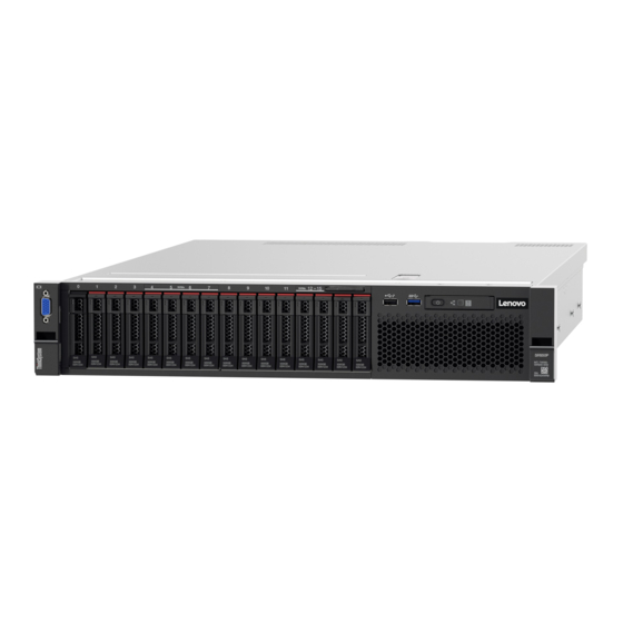
Chapter 1. Introduction The ThinkSystem SR850P is a 2U rack server designed for high-volume network transaction processing. This high-performance, multi-core server is ideally suited for networking environments that require superior processor performance, input/output (I/O) flexibility, and high manageability. Figure 1. ThinkSystem SR850P The server comes with a limited warranty. - Page 10 For a list of supported memory modules, see https://static.lenovo.com/us/en/ serverproven/index.shtml Drive expansion Sixteen 2.5-inch drive bays: • Eight 2.5-inch hot-swap SATA/SAS drive bays (bay 0-3, 8-11) • Eight 2.5-inch hot-swap SATA/SAS/NVMe drive bays (bay 4-7, 12-15) ThinkSystem SR850P Maintenance Manual...
- Page 11 • Slot 10: PCI Express 3.0 x16 • Slot 11: PCI Express 3.0 x16 (supports PCIe switch card) Integrated functions • Lenovo XClarity Controller (XCC), which provides service processor control and monitoring functions, video controller, and remote keyboard, video, mouse, and remote drive capabilities.
- Page 12 With the maximum configuration of four processors, 48 memory modules, 16 drives, and two power supply units: • Sound power: – Idle: 5.5 bels – Operating: 6.3 bels • Sound pressure – Idle: 39 dBA – Operating: 46 dBA ThinkSystem SR850P Maintenance Manual...
-
Page 13: Particulate Contamination
If Lenovo determines that the levels of particulates or gases in your environment have caused damage to the device, Lenovo may condition provision of repair or replacement of devices or parts on implementation of appropriate remedial measures to mitigate such environmental contamination. -
Page 14: Firmware Updates
• Best practices related to updating firmware is available at the following site: – http://lenovopress.com/LP0656 • The latest firmware can be found at the following site: – http://datacentersupport.lenovo.com/products/servers/thinksystem/sr850p/7d2f/downloads/driver-list • You can subscribe to product notification to stay up to date on firmware updates: – https://datacentersupport.lenovo.com/tw/en/solutions/ht509500 ThinkSystem SR850P Maintenance Manual... - Page 15 Hat Enterprise Linux (RHEL) and SUSE Linux Enterprise Server (SLES) operating system distributions. Machine-type-specific firmware-only UXSPs are also available. Firmware updating tools See the following table to determine the best Lenovo tool to use for installing and setting up the firmware: Tool Update...
- Page 16 2. For BMC and UEFI firmware updates. • Lenovo XClarity Provisioning Manager From Lenovo XClarity Provisioning Manager, you can update the Lenovo XClarity Controller firmware, the UEFI firmware, and the Lenovo XClarity Provisioning Manager software. Note: By default, the Lenovo XClarity Provisioning Manager Graphical User Interface is displayed when you start the server and press the key specified in the on-screen instructions.
- Page 17 If you need to install a specific update, you can use the Lenovo XClarity Controller interface for a specific server. Notes: – To perform an in-band update through Windows or Linux, the operating system driver must be installed and the Ethernet-over-USB (sometimes called LAN over USB) interface must be enabled.
-
Page 18: Tech Tips
Tech Tips Lenovo continually updates the support website with the latest tips and techniques that you can use to solve issues that your server might encounter. These Tech Tips (also called retain tips or service bulletins) provide procedures to work around issues or solve problems related to the operation of your server. -
Page 19: Power Off The Server
Power off the server The server remains in a standby state when it is connected to a power source, allowing the Lenovo XClarity Controller to respond to remote power-on requests. To remove all power from the server (power status LED off), you must disconnect all power cables. - Page 20 ThinkSystem SR850P Maintenance Manual...
-
Page 21: Chapter 2. Server Components
Use the information in this section to learn about each of the components associated with your server. Identifying your server When you contact Lenovo for help, the machine type, model, and serial number information helps support technicians to identify your server and provide faster service. - Page 22 Identification button/LED (blue) Drive status LED (yellow) System error LED (yellow) Pull-out information tab Front operator panel with optional pull-out LCD display USB 1 (USB 2.0 with Lenovo XClarity Controller Rack release latches management) 2.5-inch drive bays USB 2 Power button/LED (green) VGA connector (optional): Connect a monitor to this connector.
- Page 23 Controller mobile application. When a mobile device is connected to this USB port, an Ethernet over USB connection is established between the mobile application running on the device and the XClarity Controller. Select Network in BMC Configuration to view or modify USB 2.0 with Lenovo XClarity Controller management settings. Four types of settings are available: –...
-
Page 24: Front Operator Panel
Identification button/LED (blue) Use this blue LED to visually locate the server among other servers. This LED is also used as a presence detection button. You can use Lenovo XClarity Administrator to light this LED remotely. System error LED (yellow) When this yellow LED is lit, it indicates that a system error has occurred. - Page 25 Your front operator panel may come with a LCD display, which is accessible with a pull on the latch on the right of the front operator panel. Figure 6. Front operator panel and LCD display The LCD system information display panel attached to the front of the server allows quick access to system status, firmware, network, and health information.
- Page 26 Following is the list of options available on the front operator panel. Switch between an option and the subordinate information entries with Select (√) button, and switch among options or information entries with Scroll up (▼) and Scroll down (▲) buttons. ThinkSystem SR850P Maintenance Manual...
- Page 27 Table 7. Options available on the front operator panel Option Description System error System error provides the total number of errors the system encountered, and the description of these errors. The information is displayed as following: System Has Encountered X Errors Whereas X is the total number of system errors encountered.
- Page 28 PS1 AC Voltage: YYY V PS2 AC Voltage: YYY V • Estimated power consumption is displayed as following: Sytem Power: ZZ W Whereas • XX is the temperature. • YYY is the AC voltage. • ZZ is the wattage. ThinkSystem SR850P Maintenance Manual...
-
Page 29: Rear View
Table 7. Options available on the front operator panel (continued) Actions Actions provides the following available actions, which come in effect by pressing and holding on the select button for three seconds: • Restore XCC default settings is displayed as following: RESTORE XCC DEFAULTS? HOLD v FOR 3s •... - Page 30 – Slot 4: Not available – Slot 5: PCI Express 3.0 x8 M.2 backplane (slot 6): Install M.2 backplane to this slot. See “M.2 drive and backplane replacement” on page 72 for more details. LOM adapter (slot 7): ThinkSystem SR850P Maintenance Manual...
- Page 31 Insert LOM adapter into this slot (see “System-board connectors” on page 25 for the location of the LOM adapter slot on the system board and “LOM adapter replacement” on page 69 for information about the installation of the LOM adapter). AC power LED: Each hot-swap power supply comes with an ac power LED and a dc power LED.
- Page 32 Use this connector to manage the server, by using a dedicated management network. If you use this connector, the Lenovo XClarity Controller cannot be accessed directly from the production network. A dedicated management network provides additional security by physically separating the management network traffic from the production network.
-
Page 33: System-Board Connectors
Table 9. System-board connectors PCIe slot 11, 10, 8 Front operator panel connector PCIe slot 7 (LOM adapter) USB 1 (USB 2.0 with Lenovo XClarity Controller management) Backplane connector 2 PCIe slot 6 (M.2 backplane) PCIe slot 3-5 (PCIe riser-card) -
Page 34: Switches, Jumpers, And Buttons
The following table describes the functions of the SW613 switch block on the system board. Table 11. System-board SW13 switch block descriptions Switch number Default position Host TPM Physical Presence Host TPM Physical Presence disable enable ThinkSystem SR850P Maintenance Manual... -
Page 35: System-Board Leds
You can also use it to force a blue-screen memory dump (use this button only when you are directed to do so by Lenovo Support). System-board LEDs Use this information to locate the system-board LEDs. -
Page 36: Processor And Memory Expansion Tray
Processor and memory expansion tray Use this information to locate the connectors and LEDs on the processor and memory expansion tray. The following illustrations show the connectors and LEDs on the processor and memory expansion tray. ThinkSystem SR850P Maintenance Manual... - Page 37 Figure 14. Processor and memory expansion tray Table 14. Components on the processor and memory expansion tray Power supply 2 connector DIMM slot 31-42 Tray handle Processor 3 DIMM slot 43-48 DIMM slot 25-30 Processor 4 Captive screws Figure 15. LEDs on the processor and memory expansion tray Table 15.
- Page 38 Figure 16. Connectors on the processor and memory expansion tray Table 16. Connectors on the processor and memory expansion tray NVMe signal cable connector 0-1 NVMe signal cable connector 2-3 ThinkSystem SR850P Maintenance Manual...
-
Page 39: Pcie Riser-Cards
PCIe riser-cards Use this information to locate the connectors on the optional PCIe riser-cards. x8/x8/x8 PCIe FH Riser Assembly Figure 17. x8/x8/x8 PCIe FH Riser Assembly Table 17. Components of x8/x8/x8 PCIe FH Riser Assembly PCIe full-height riser cage PCI Express 3.0 x8 (slot 4) PCI Express 3.0 x8 (slot 3) PCI Express 3.0 x8 (slot 5) x8/x8/x8ML2 PCIe FH Riser Assembly... -
Page 40: 2.5-Inch Drive Backplanes
Table 20. Components of x8/x16 PCIe FH Riser Assembly PCIe full-height riser cage PCI Express 3.0 x8 (slot 5) PCI Express 3.0 x16 (slot 3) 2.5-inch drive backplanes Use this information to locate the connectors on the optional 2.5-inch drive backplanes. ThinkSystem SR850P Maintenance Manual... - Page 41 2.5-inch SATA/SAS 8-bay backplane Figure 21. 2.5-inch SATA/SAS 8-bay backplane Table 21. Connectors on 2.5-inch SATA/SAS 8-bay backplane SATA/SAS connector 1 SATA/SAS connector 0 Power/configuration cable connector 2.5-inch SATA/SAS 8-bay backplane comes with: • Eight SATA/SAS drive connectors with bay numbers of 0-7 or 8-15, depending on the location installed. •...
-
Page 42: Raid Adapters
SATA/SAS RAID adapter (8i) with two SATA/SAS connectors (C0, C1) Figure 24. Connectors on SATA/SAS RAID adapter (16i) Table 24. SATA/SAS RAID adapter (16i) SATA/SAS RAID adapter (16i) with four SATA/SAS connectors (C0, C1, C2, C3) Figure 25. Connectors on PCIe switch card ThinkSystem SR850P Maintenance Manual... -
Page 43: Internal Cable Routing
Table 25. PCIe switch card PCIe switch card with four SATA/SAS connectors (C0, C1, C2, C3) Internal cable routing This section provides information about routing the cables when you install components in the server. For more information about the requirements for cables and connecting devices, see the documentation that comes with these devices. - Page 44 Power cable connector on the drive backplane Two types of drive backplanes are supported by this system: • 2.5-inch SATA/SAS 8-bay backplane (referred to as “8-bay backplane”) • 2.5-inch AnyBay 8-bay backplane (referred to as “AnyBay backplane”) ThinkSystem SR850P Maintenance Manual...
- Page 45 Connecting signal cables to one backplane When one backplane is installed, see the following illustrations for cable routing. One 8-bay backplane Figure 29. Cable routing, 8-bay backplane Table 27. Cables and adapters for routing SATA/SAS RAID adapter (8i) SATA/SAS signal cables (720 mm) One AnyBay backplane Note: Install the processor and memory expansion tray before connecting the signal cables to NVMe connectors on the expansion tray (see...
- Page 46 Figure 30. Cable routing, AnyBay backplane Table 28. Cables and adapters for routing Direct NVMe signal cables for processor and memory SATA/SAS RAID adapter (8i) expansion tray NVMe connectors on the processor and memory SATA/SAS signal cables (720 mm) expansion tray ThinkSystem SR850P Maintenance Manual...
- Page 47 Connecting signal cables to two backplanes When two backplanes are installed, see the following illustrations for cable routing. 8-bay backplane + 8-bay backplane Two options are available for this combination: 1. With SATA/SAS RAID adapter (16i) Figure 31. Cable routing, 8-bay backplane + 8-bay backplane Table 29.
- Page 48 0-7, and the AnyBay backplane to drive bay 8-15. • Install the processor and memory expansion tray before connecting the signal cables to NVMe connectors on the expansion tray (see “Install the processor and memory expansion tray” on page 113). ThinkSystem SR850P Maintenance Manual...
- Page 49 Two options are available for this combination: 1. With SATA/SAS RAID adapter (16i) Figure 33. Cable routing, 8-bay backplane + AnyBay backplane Table 31. Cables and adapters for routing SATA/SAS RAID adapter (16i) SATA/SAS signal cables (720 mm) NVMe connectors on the processor and memory SATA/SAS signal cables (900 mm) expansion tray Direct NVMe signal cables for processor and...
- Page 50 Direct NVMe signal cables for processor and memory expansion tray NVMe connectors on the processor and memory SATA/SAS signal cables (720 mm) expansion tray SATA/SAS RAID adapter (8i) SATA/SAS signal cables (720 mm) AnyBay backplane + AnyBay backplane ThinkSystem SR850P Maintenance Manual...
- Page 51 Two options are available for this combination: Note: Install the processor and memory expansion tray before connecting the signal cables to NVMe connectors on the expansion tray (see “Install the processor and memory expansion tray” on page 113). 1. With one SATA/SAS RAID adapter (16i) Figure 35.
-
Page 52: Parts List
2. Click Parts & Accessories ➙ Parts Lookup. 3. Enter either the serial number or the machine type model for your server to see the parts for your server. Note: Depending on the model, your server might look slightly different from the illustration. ThinkSystem SR850P Maintenance Manual... - Page 53 The parts listed in the following table are identified as one of the following: • Tier 1 customer replaceable unit (CRU): Replacement of Tier 1 CRUs is your responsibility. If Lenovo installs a Tier 1 CRU at your request with no service agreement, you will be charged for the installation.
- Page 54 • Tier 2 customer replaceable unit: You may install a Tier 2 CRU yourself or request Lenovo to install it, at no additional charge, under the type of warranty service that is designated for your server. • Field replaceable unit (FRU): FRUs must be installed only by trained service technicians.
- Page 55 Table 35. Parts listing (continued) Index Description Tier 1 CRU Tier 2 CRU Consuma- ble and Structural part Memory module √ DC Persistent Memory (DCPMM) √ Processor √ Heatsink √ 2.5-inch SATA/SAS 8-bay backplane √ 2.5-inch AnyBay (SATA/SAS/NVMe) 8-bay √ backplane Fan cage √...
-
Page 56: Power Cords
The cord set should have the appropriate safety approvals for the country in which the equipment will be installed. • Power cords for a specific country or region are usually available only in that country or region. ThinkSystem SR850P Maintenance Manual... -
Page 57: Chapter 3. Hardware Replacement Procedures
– Make sure that you can stand steadily without slipping. – Distribute the weight of the object equally between your feet. – Use a slow lifting force. Never move suddenly or twist when you lift a heavy object. © Copyright Lenovo 2019, 2022... -
Page 58: System Reliability Guidelines
• Every air baffle that comes with the server must be installed when the server starts (some servers might come with more than one air baffle). Operating the server with a missing air baffle might damage the processor. • All processor sockets must contain either a socket cover or a processor with heat sink. ThinkSystem SR850P Maintenance Manual... -
Page 59: Working Inside The Server With The Power On
• When more than one processor is installed, fan population rules for each server must be strictly followed. Working inside the server with the power on You might need to keep the power on with the server cover removed to look at system information on the display panel or to replace hot-swap components. -
Page 60: Inch Hot-Swap Drive And Drive Backplane
Rotate the backplane from the top toward the center of the server to disengage it from the retention latches. If you are instructed to return the component or optional device, follow all packaging instructions, and use any packaging materials for shipping that are supplied to you. ThinkSystem SR850P Maintenance Manual... -
Page 61: Install A Drive Backplane
Install a drive backplane Use this procedure to install a drive backplane. Before installing a drive backplane: 1. Read the safety information and installation guidelines (see “Safety” on page iii “Installation Guidelines” on page 49). 2. Touch the static-protective package that contains the component to any unpainted metal surface on the server;... -
Page 62: Install A 2.5-Inch Hot-Swap Drive
2. Touch the static-protective package that contains the component to any unpainted metal surface on the server; then, remove it from the package and place it on a static-protective surface. 3. Watch the procedure A video of this procedure is available at YouTube: https://www.youtube.com/playlist?list= PLYV5R7hVcs-B2y7oAb54mfyuLrIusa_qE ThinkSystem SR850P Maintenance Manual... -
Page 63: Cmos Battery (Cr2032) Replacement
To install a 2.5-inch drive, complete the following steps: Step 1. If new drives are to be added, see “Install a 2.5-inch drive” in ThinkSystem SR850P Setup Guide to determine available drive bays to the new drives. Step 2. Gently rotate the release latch away to unlock the drive handle. - Page 64 S004 CAUTION: When replacing the lithium battery, use only Lenovo specified part number or an equivalent type battery recommended by the manufacturer. If your system has a module containing a lithium battery, replace it only with the same module type made by the same manufacturer. The battery contains lithium and can explode if not properly used, handled, or disposed of.
- Page 65 5. Remove the top cover (see “Remove the top cover” on page 133). 6. Remove the processor and memory expansion tray and the expansion tray air baffle (see “Remove the processor and memory expansion tray” on page 110). Figure 42. CMOS battery location on the system board Table 36.
-
Page 66: Install The Cmos Battery (Cr2032)
S004 CAUTION: When replacing the lithium battery, use only Lenovo specified part number or an equivalent type battery recommended by the manufacturer. If your system has a module containing a lithium battery, replace it only with the same module type made by the same manufacturer. The battery contains lithium and can explode if not properly used, handled, or disposed of. -
Page 67: Fan And Fan Cage Replacement
Before installing the CMOS battery: 1. Read the safety information and installation guidelines (see “Safety” on page iii “Installation Guidelines” on page 49). 2. Touch the static-protective package that contains the component to any unpainted metal surface on the server; then, remove it from the package and place it on a static-protective surface. 3. - Page 68 133). To remove the fan cage assembly, complete the following steps: Step 1. Lift and rotate the fan cage release latches to disengage the fan cage assembly from the server. Figure 45. Fan cage assembly removal ThinkSystem SR850P Maintenance Manual...
-
Page 69: Install The Fan Cage Assembly
Step 2. Lift the fan cage assembly from the server. If you are instructed to return the component or optional device, follow all packaging instructions, and use any packaging materials for shipping that are supplied to you. Install the fan cage assembly Use this procedure to install the fan cage assembly. -
Page 70: Remove A Hot-Swap Fan
“Remove the top cover” on page 133). To remove a hot-swap-fan, complete the following steps: Step 1. Pinch on the top of the fan, and press on the latch to release the fan from the connector. ThinkSystem SR850P Maintenance Manual... -
Page 71: Install A Hot-Swap Fan
Figure 47. Hot-swap fan removal Attention: When replacing a fan with power on, complete the replacement within 30 seconds to ensure proper operation. Step 2. Lift the fan out from the fan cage. If you are instructed to return the component or optional device, follow all packaging instructions, and use any packaging materials for shipping that are supplied to you. -
Page 72: Front Vga Assembly Replacement
2. Install the server in the rack. Front VGA assembly replacement Use this procedure to remove or install the front VGA assembly. Remove the front VGA assembly Use this procedure to remove the front VGA assembly. Before removing the front VGA assembly: ThinkSystem SR850P Maintenance Manual... - Page 73 1. Read the safety information and installation guidelines (see “Safety” on page iii “Installation Guidelines” on page 49). 2. Turn off the server and peripheral devices and disconnect the power cords and all external cables (see “Power off the server” on page 11).
- Page 74 Tilt the cable cover and remove it from the server. Figure 51. Front VGA assembly removal Step 5. Grasp the front VGA assembly, and pull it slightly forward the front of the server to remove it. Figure 52. Front VGA assembly removal ThinkSystem SR850P Maintenance Manual...
-
Page 75: Install The Front Vga Assembly
If you are instructed to return the component or optional device, follow all packaging instructions, and use any packaging materials for shipping that are supplied to you. Install the front VGA assembly Use this procedure to install the front VGA assembly. Before installing the front VGA assembly: 1. - Page 76 Tile and install the cable cover. Figure 55. Front VGA assembly installation Step 5. Install the front VGA assembly with four screws. Figure 56. Front VGA assembly installation Step 6. Connect the front video cable to the system board. ThinkSystem SR850P Maintenance Manual...
-
Page 77: Lom Adapter Replacement
Figure 57. Front VGA assembly installation After installing front VGA assembly, complete the following steps: 1. Reinstall the fan cage (see “Install the fan cage assembly” on page 2. Reinstall the top cover (see “Install the top cover” on page 134). -
Page 78: Install The Lom Adapter
Following are the requirements: • 1GbE LOM adapter: maximal bandwidth of network environment is 1GB. • 10GbE LOM adapter: minimal bandwidth of network environment is 1GB. 5. Attach the mounting bracket with the two screws as illustrated. ThinkSystem SR850P Maintenance Manual... - Page 79 Figure 59. LOM adapter assembly To install the LOM adapter, complete the following steps: Step 1. Open the retention latch. Step 2. Align the LOM adapter to the connector, and push it in. Step 3. Tighten the captive thumbscrew to lock it to the system board. Figure 60.
-
Page 80: M.2 Drive And Backplane Replacement
“Power off the server” on page 11). 3. If the server is installed in a rack, slide the server out on its rack slide rails to gain access to the top cover, or remove the server from the rack. ThinkSystem SR850P Maintenance Manual... - Page 81 4. Remove the top cover (see “Remove the top cover” on page 133). 5. Disconnect the USB 3.0 cable of operator panel tray assembly, and remove it vertically from the system board. Figure 62. Removing USB 3.0 connector vertically 6. Remove PCIe riser-card if necessary (see “Remove the PCIe riser-card assembly”...
-
Page 82: Install The M.2 Backplane
Align the openings located at the bottom of the blue plastic supports at each end of the M.2 backplane with the guide pin on the system board and T-head pins on the hard drive cage; then, insert the backplane in the system board connector. Press down on the M.2 backplane to fully seat ThinkSystem SR850P Maintenance Manual... -
Page 83: Remove An M.2 Drive From The
Figure 65. M.2 backplane installation After installing the M.2 backplane, complete the following steps: 1. Reinstall the PCIe riser-card if necessary (see “Install the PCIe riser-card assembly” on page 89). 2. Reinstall the LOM adapter if necessary (see “Install the LOM adapter” on page 70). -
Page 84: Install An M.2 Drive In The M.2 Backplane
Insert the M.2 drive at an angle (approximately 30 degrees) into the connector and rotate it until the notch catches on the lip of the retainer; then, slide the retainer forward (toward the connector) to secure the M.2 drive in the M.2 backplane. ThinkSystem SR850P Maintenance Manual... -
Page 85: Memory Module Replacement
Figure 68. M.2 drive installation Attention: When sliding the retainer forward, make sure the two nubs on the retainer enter the small holes on the M.2 backplane. Once they enter the holes, you will hear a soft “click” sound. Figure 69. M.2 drive installation with the retainers in place After installing an M.2 drive in the M.2 backplane, see “Install the M.2 backplane”... - Page 86 “Remove the top cover” on page 133). 7. If you are not replacing the memory module that you removed, see the ThinkSystem SR850P Memory Population Reference for the required installation order of the remaining memory modules. 8. If you are removing memory modules from the processor and memory expansion tray, do not remove the expansion tray.
- Page 87 9. If you are removing memory modules from the system board, make sure to remove the expansion tray (see “Remove the processor and memory expansion tray” on page 110) and the air baffle that is installed on the system board. Figure 71.
-
Page 88: Install A Memory Module
3. If you are installing memory modules on the processor and memory expansion tray, do not remove the expansion tray. Only remove the air baffle that is installed on the expansion tray. Figure 73. Air baffle removal from the processor and memory expansion tray ThinkSystem SR850P Maintenance Manual... - Page 89 4. If you are installing memory modules on the system board, make sure to remove the expansion tray (see “Remove the processor and memory expansion tray” on page 110) and the air baffle that is installed on the system board. Figure 74.
-
Page 90: Operator Panel Tray Assembly And Front Operator Panel Replacement
3. If the server is installed in a rack, slide the server out on its rack slide rails to gain access to the top cover, or remove the server from the rack. 4. Watch the procedure ThinkSystem SR850P Maintenance Manual... - Page 91 A video of this procedure is available at YouTube: https://www.youtube.com/playlist?list= PLYV5R7hVcs-B2y7oAb54mfyuLrIusa_qE 5. Remove the top cover (see “Remove the top cover” on page 133). To remove the operator panel tray assembly, complete the following steps: Step 1. Remove the fan cage assembly (see “Remove the fan cage assembly”...
-
Page 92: Install The Operator Panel Tray Assembly
To install the operator panel tray assembly, complete the following steps: Step 1. Align the operator panel tray assembly with the slot in the front of the server, and insert the tray assembly until it clicks into place. ThinkSystem SR850P Maintenance Manual... - Page 93 Figure 79. Operator panel tray assembly installation Step 2. Install the tray assembly to the server with a screw. Step 3. Connect the front operator panel cable and USB cables to the system board. Figure 80. USB 2.0 cable and front operator panel cable Table 39.
-
Page 94: Remove The Front Operator Panel
Figure 82. Front operator panel removal If you are instructed to return the component or optional device, follow all packaging instructions, and use any packaging materials for shipping that are supplied to you. ThinkSystem SR850P Maintenance Manual... -
Page 95: Install The Front Operator Panel
Install the front operator panel Use this procedure to install the front operator panel. Before installing the front operator panel: 1. Read the safety information and installation guidelines (see “Safety” on page iii “Installation Guidelines” on page 49). 2. Touch the static-protective package that contains the component to any unpainted metal surface on the server;... - Page 96 Grasp the PCIe riser-card assembly at the touch-points, and lift it out from the system board. Figure 85. PCIe riser-card assembly removal Step 3. Remove the screws that fix the PCIe riser-card, and slightly push it away to detach it from the riser- cage. ThinkSystem SR850P Maintenance Manual...
-
Page 97: Install The Pcie Riser-Card Assembly
Figure 86. PCIe riser-card removal If you are instructed to return the component or optional device, follow all packaging instructions, and use any packaging materials for shipping that are supplied to you. Install the PCIe riser-card assembly Use this procedure to install the PCIe riser-card assembly. Before installing the PCIe riser-card assembly: 1. - Page 98 Install the PCIe riser-card to the riser-cage with screws. Figure 89. PCIe riser-card assembly Step 2. Align the PCIe riser-card assembly with the connector on the system board; then, push it in until it clicks in place. ThinkSystem SR850P Maintenance Manual...
-
Page 99: Remove An Adapter
Figure 90. PCIe riser-card assembly installation Step 3. Reconnect all the cables disconnected previously. After installing the PCIe riser-card assembly, complete the following steps: 1. Reinstall the top cover (see “Install the top cover” on page 134). 2. Reconnect the power cords and any cables that you removed. 3. -
Page 100: Install An Adapter
If you are instructed to return the component or optional device, follow all packaging instructions, and use any packaging materials for shipping that are supplied to you. Install an adapter Use this procedure to install an adapter. Before installing an adapter: ThinkSystem SR850P Maintenance Manual... - Page 101 1. Read the safety information and installation guidelines (see “Safety” on page iii “Installation Guidelines” on page 49). 2. Touch the static-protective package that contains the component to any unpainted metal surface on the server; then, remove it from the package and place it on a static-protective surface. 3.
-
Page 102: Power Supply Unit Replacement
5. Power on the server and any peripheral devices. Power supply unit replacement Use this procedure to install or remove power supply units. Remove a hot-swap power supply unit Use this procedure to remove a hot-swap power supply unit. S002 CAUTION: ThinkSystem SR850P Maintenance Manual... - Page 103 The power-control button on the device and the power switch on the power supply do not turn off the electrical current supplied to the device. The device also might have more than one power cord. To remove all electrical current from the device, ensure that all power cords are disconnected from the power source.
- Page 104 3. Watch the procedure A video of this procedure is available at YouTube: https://www.youtube.com/playlist?list= PLYV5R7hVcs-B2y7oAb54mfyuLrIusa_qE To remove a hot-swap power supply unit, complete the following steps: Step 1. Press and hold on the orange release tab. ThinkSystem SR850P Maintenance Manual...
-
Page 105: Install A Hot-Swap Power Supply Unit
Figure 96. Power supply unit removal Step 2. Grasp the handle, pull the power supply out of the server and set it aside. Note: Fill the power supply bay with a filler if you are not replacing a new power supply immediately. - Page 106 • 1600-watt platinum power supply – Input power 115V or 220V ac Before installing a hot-swap power supply: 1. Read the safety information and installation guidelines (see “Safety” on page iii “Installation Guidelines” on page 49). ThinkSystem SR850P Maintenance Manual...
- Page 107 2. Touch the static-protective package that contains the component to any unpainted metal surface on the server; then, remove it from the package and place it on a static-protective surface. 3. If the server is in a rack, adjust the cable management arm (CMA) to gain access to the power supply bay.
- Page 108 • Power supply 1 is on the bottom, while power supply 2 is on the top. For more details, see “Rear view” on page Step 3. Connect the power cord to the power supply unit, and make sure it's properly connected to the power. ThinkSystem SR850P Maintenance Manual...
-
Page 109: Processor And Heat Sink Replacement
Processor and heat sink replacement Use the following procedures to replace an assembled processor and heat sink, known as a processor-heat- sink module (PHM), a processor, or a heat sink. Attention: Before you begin replacing a processor, make sure that you have an alcohol cleaning pad (part number 00MP352) and gray thermal grease (part number 41Y9292). - Page 110 110). Figure 99. Processor locations Table 40. Processor locations Processor 3 Processor 4 Processor 1 Processor 2 Complete the following steps to remove a PHM. Step 1. Remove the PHM from the system board. ThinkSystem SR850P Maintenance Manual...
- Page 111 Figure 100. Removing a PHM Attention: To prevent damage to components, make sure that you follow the indicated loosening sequence. Fully loosen the Torx T30 captive fasteners on the processor-heat-sink module in the removal sequence shown on the heat-sink label. Lift the processor-heat-sink module from the processor socket.
- Page 112 • If you are replacing the heat sink, you will be reusing the processor. Wipe the thermal grease from the top of the processor using an alcohol cleaning pad. If you are instructed to return the component or optional device, follow all packaging instructions, and use any packaging materials for shipping that are supplied to you. ThinkSystem SR850P Maintenance Manual...
-
Page 113: Install A Processor And Heat Sink
• Before you install a new PHM or replacement processor, update your system firmware to the latest level. See “Update the firmware” in the ThinkSystem SR850P Setup Guide. • Installing an additional PHM can change the memory requirements for your system. See ThinkSystem SR850P Memory Population Reference for a list of processor-to-memory relationships. - Page 114 To prevent the processor from falling out of the retainer after it is inserted, keep the processor- contact side up and hold the processor-retainer assembly by the sides of the retainer. ThinkSystem SR850P Maintenance Manual...
- Page 115 3) If there is any old thermal grease on the processor, gently clean the top of the processor using an alcohol cleaning pad. Note: If you are applying new thermal grease on the top of the processor, make sure to do it after the alcohol has fully evaporated.
- Page 116 Insert the processor-retainer clips into the holes on the heat sink. c. Press the retainer into place until the clips at all four corners engage. ThinkSystem SR850P Maintenance Manual...
- Page 117 Figure 106. Processor locations Table 41. Processor locations Processor 3 Processor 4 Processor 1 Processor 2 Step 1. Remove the processor socket cover, if one is installed on the processor socket, by placing your fingers in the half-circles at each end of the cover and lifting it from the system board. Step 2.
-
Page 118: Processor And Memory Expansion Tray
Processor and memory expansion tray replacement Use this procedure to remove or install expansion tray air baffle and processor and memory expansion tray. Remove the processor and memory expansion tray Use this procedure to remove the processor and memory expansion tray. ThinkSystem SR850P Maintenance Manual... - Page 119 Before removing the processor and memory expansion tray: 1. Read the safety information and installation guidelines (see “Safety” on page iii “Installation Guidelines” on page 49). 2. Turn off the server and peripheral devices and disconnect the power cords and all external cables (see “Power off the server”...
- Page 120 Figure 110. Processor and memory expansion tray removal Step 4. Grasp the handle and carefully lift the expansion tray from the server; then, place it on a flat surface. After removing the processor and memory expansion tray: ThinkSystem SR850P Maintenance Manual...
-
Page 121: Install The Processor And Memory Expansion
• If you are instructed to return the component or optional device, follow all packaging instructions, and use any packaging materials for shipping that are supplied to you. Important: Before you return the expansion tray, make sure that you install the processor socket dust covers from the new expansion tray. - Page 122 Grip on the blue touch point on the handle of the expansion tray, and lift it up; then, lower the tray vertically into the server with nailheads aligned to the slots on both sides. Step 4. Rotate the handle all the way down. This connects and fix the expansion tray to the system board. ThinkSystem SR850P Maintenance Manual...
- Page 123 Figure 112. Processor and memory expansion tray installation Step 5. Tighten the two captive screws to secure the handle of the expansion tray. Figure 113. Processor and memory expansion tray installation Step 6. Slide the power supply 2 back into the chassis. Step 7.
-
Page 124: Security Bezel Replacement
3. Watch the procedure A video of this procedure is available at YouTube: https://www.youtube.com/playlist?list= PLYV5R7hVcs-B2y7oAb54mfyuLrIusa_qE Step 1. Insert the key that comes with the server and rotate it clockwise to unlock the security bezel to the open position. ThinkSystem SR850P Maintenance Manual... -
Page 125: Install The Security Bezel
A video of this procedure is available at YouTube: https://www.youtube.com/playlist?list= PLYV5R7hVcs-B2y7oAb54mfyuLrIusa_qE 3. If you have removed the rack handles, reinstall it (see ThinkSystem SR850P Rack Installation Guide). Step 1. Carefully insert the tabs on the security bezel into the slots on the right rack handle. Then, press and hold the release latch, and pivot the security bezel inward until the other side clicks into place. -
Page 126: System Board Replacement
Before removing the system board: 1. Record all system configuration information, such as Lenovo XClarity Controller (XCC) IP addresses, vital product data, and the machine type, model number, serial number, Universally Unique Identifier, and asset tag of the server. - Page 127 4. Read the safety information and installation guidelines (see “Safety” on page iii “Installation Guidelines” on page 49). 5. Turn off the server and peripheral devices and disconnect the power cords and all external cables (see “Power off the server” on page 11).
- Page 128 Step 14. Rotate the long side of the system board up, and remove the board from the server. Figure 121. System board removal Note: This handle only serves the purpose of removing system board. Do not attempt to lift the whole server with it. After removing the system board: ThinkSystem SR850P Maintenance Manual...
-
Page 129: Install The System Board
• If you are instructed to return the component or optional device, follow all packaging instructions, and use any packaging materials for shipping that are supplied to you. Important: Before you return the system board, make sure that you install the processor socket dust covers from the new system board. - Page 130 3. Install any components that you removed from the failing system board. See the related topics in “Hardware replacement procedures.” 4. Update the machine type and serial number with new vital product data (VPD). Use the Lenovo XClarity Provisioning Manager to update the machine type and serial number. See “Update the machine type...
-
Page 131: Update The Machine Type And Serial
• From Lenovo XClarity Provisioning Manager To update the machine type and serial number from Lenovo XClarity Provisioning Manager: 1. Start the server and press the key according to the on-screen instructions to display the Lenovo XClarity Provisioning Manager interface. -
Page 132: Enable Tpm/Tcm
SYSTEM_PROD_DATA.SysInfoProdName <m/t_model> −−bmc xcc_user_id:xcc_password@xcc_external_ip onecli config set SYSTEM_PROD_DATA.SysInfoSerialNum <s/n> −−bmc xcc_user_id:xcc_password@xcc_external_ip 4. Reset the Lenovo XClarity Controller to the factory defaults. See “Resetting the BMC to Factory Default” section in the XCC documentation compatible with your server at https:// sysmgt.lenovofiles.com/help/topic/lxcc_frontend/lxcc_overview.html Enable TPM/TCM The server supports Trusted Platform Module (TPM), Version 1.2 or Version 2.0... - Page 133 Note: Although the setting undefined is available as a policy setting, it should not be used. • From Lenovo XClarity Essentials OneCLI Note: Please note that a Local IPMI user and password must be setup in Lenovo XClarity Controller for remote accessing to the target system.
- Page 134 Physical Presence Policy is enabled with a timeout of 30 minutes. There are two ways to assert the Physical Presence: 1. If the Physical Presence Policy is enabled, you can assert Physical Presence through the Lenovo XClarity Provisioning Manager or through the Lenovo XClarity Controller.
- Page 135 Set the TPM version To be able to set the TPM version, Physical Presence must be asserted. The Lenovo XClarity Provisioning Manager or the Lenovo XClarity Essentials OneCLI can be used to set the TPM version. To set the TPM version: 1.
-
Page 136: Enable Uefi Secure Boot
To enable UEFI Secure Boot from Lenovo XClarity Provisioning Manager: 1. Start the server and press the key specified in the on-screen instructions to display the Lenovo XClarity Provisioning Manager interface. (For more information, see the “Startup” section in the LXPM documentation compatible with your server at https://sysmgt.lenovofiles.com/help/topic/lxpm_frontend/... -
Page 137: Tcm/Tpm Adapter Replacement
TCM/TPM adapter replacement Use this procedure to remove or install the TCM/TPM adapter. Remove the TCM/TPM adapter (for Chinese Mainland only) Use this information to remove the TCM/TPM adapter. “Read the “Power off “ATTENTION: installation the server Static Sensitive Device Guidelines”... -
Page 138: Install The Tcm/Tpm Adapter
Use this information to install the TCM/TPM adapter. “Read the “Power off “ATTENTION: installation the server Static Sensitive Device Guidelines” on for this task” Ground package before opening” page 49 on page 11 on page 51 ThinkSystem SR850P Maintenance Manual... - Page 139 Before installing the TCM/TPM adapter: 1. Read the safety information and installation guidelines (see “Safety” on page iii “Installation Guidelines” on page 49). 2. Touch the static-protective package that contains the component to any unpainted metal surface on the server; then, remove it from the package and place it on a static-protective surface. 3.
-
Page 140: Top Cover Replacement
“Install the top cover” on page 134). 3. Reconnect the power cords and any cables that you removed. 4. Power on the server and any peripheral devices. Top cover replacement Use this procedure to install or remove the top cover. ThinkSystem SR850P Maintenance Manual... -
Page 141: Remove The Top Cover
Remove the top cover Follow the instructions in this section to remove the top cover. S014 CAUTION: Hazardous voltage, current, and energy levels might be present. Only a qualified service technician is authorized to remove the covers where the label is attached. S033 CAUTION: Hazardous energy present. -
Page 142: Install The Top Cover
Before installing the top cover: 1. Read the safety information and installation guidelines (see “Safety” on page iii “Installation Guidelines” on page 49). 2. Watch the procedure ThinkSystem SR850P Maintenance Manual... -
Page 143: Complete The Parts Replacement
A video of this procedure is available at YouTube: https://www.youtube.com/playlist?list= PLYV5R7hVcs-B2y7oAb54mfyuLrIusa_qE 3. Make sure all the removed components are installed, and all the disconnected cables are reconnected. To install the top cover, complete the following steps: Step 1. Press and hold on the blue tab of cover release latch; then, rotate the tip of the latch up. Step 2. - Page 144 • Reconfigure the disk arrays if you have installed or removed a hot-swap drive or a RAID adapter. See the Lenovo XClarity Provisioning Manager User Guide, which is available for download at: http:// datacentersupport.lenovo.com ThinkSystem SR850P Maintenance Manual...
-
Page 145: Chapter 4. Problem Determination
An alert is a message or other indication that signals an event or an impending event. Alerts are generated by the Lenovo XClarity Controller or by UEFI in the servers. These alerts are stored in the Lenovo XClarity Controller Event Log. If the server is managed by the Chassis Management Module 2 or by the Lenovo XClarity Administrator, alerts are automatically forwarded to those management applications. - Page 146 Lenovo XClarity Controller event log The Lenovo XClarity Controller monitors the physical state of the server and its components using sensors that measure internal physical variables such as temperature, power-supply voltages, fan speeds, and component status. The Lenovo XClarity Controller provides various interfaces to systems management software and to system administrators and users to enable remote management and control of a server.
-
Page 147: Light Path Diagnostics
“Viewing Event Logs” section in the XCC documentation compatible with your server at https:// sysmgt.lenovofiles.com/help/topic/lxcc_frontend/lxcc_overview.html Light path diagnostics Light path diagnostics is a system of LEDs on various external and internal components of the server that leads you to the failed component. When an error occurs, LEDs are lit on the front operator panel on the front of the server, then on the failed component. -
Page 148: Power Supply Leds
This LED is used as a presence detection Use this LED to locate the server among Identification button/ LED (blue) LED. You can use Lenovo XClarity other servers visually. Controller to light this LED remotely. System error LED LED on: An error has occurred. - Page 149 Normal operation The server is functioning correctly. No ac power to the server, a 1. Check the ac power to problem with the ac power the server. source, or a power supply 2. Make sure that the power has failed. cord is connected to a functioning power source.
-
Page 150: System-Board Leds
3. Save the log if necessary, and clear the log afterward. Identification LED (blue) This LED is used as a presence detection LED. You can use Lenovo XClarity Controller to light this LED remotely. Use this LED to locate the server among other servers visually. -
Page 151: General Problem Determination Procedures
• Any external devices. • Surge-suppressor device (on the server). • Printer, mouse, and non-Lenovo devices. • Each adapter. • Hard disk drives. • Memory modules until you reach the minimum configuration that is supported for the server. -
Page 152: Resolving Suspected Ethernet Controller Problems
Make sure that the device drivers on the client and server are using the same protocol. If the Ethernet controller still cannot connect to the network but the hardware appears to be working, the network administrator must investigate other possible causes of the error. ThinkSystem SR850P Maintenance Manual... -
Page 153: Troubleshooting By Symptom
1. Check the event log of the application that is managing the server and follow the suggested actions to resolve any event codes. • If you are managing the server from the Lenovo XClarity Administrator, begin with the Lenovo XClarity Administrator event log. - Page 154 Multiple hard drives fail Complete the following steps until the problem is solved: • View the Lenovo XClarity Controller event log for events related to power supplies or vibration issues and resolve those events. • Make sure that the device drivers and firmware for the hard disk drive and server are at the latest level Important: Some cluster solutions require specific code levels or coordinated code updates.
-
Page 155: Fan Problems
Green hard disk drive activity LED does not represent actual state of associated drive Complete the following steps until the problem is solved: 1. If the green hard disk drive activity LED does not flash when the drive is in use, run the diagnostics tests for the hard disk drives. -
Page 156: Keyboard, Mouse, Kvm Switch Or Usb-Device
137 for information about viewing the event log. If you are using Linux base operating system, then capture all logs back to Lenovo support for further investigation. Keyboard, mouse, KVM switch or USB-device problems Use this information to solve problems related to a keyboard, mouse, KVM switch or USB-device problems. -
Page 157: Memory Problems
• “KVM switch problems” on page 149 • “USB-device does not work” on page 149 All or some keys on the keyboard do not work 1. Make sure that: • The keyboard cable is securely connected. • The server and the monitor are turned on. 2. - Page 158 Notes: When DCPMMs are installed, run diagnostics based on the mode that is set presently: • App Direct Mode: – Run Memory Test for DRAM memory modules. – Run DCPMM Test for DCPMMs. • Memory and Mixed Memory Mode: ThinkSystem SR850P Maintenance Manual...
-
Page 159: Monitor And Video Problems
Run both Memory Test and DCPMM Test for DCPMMs. 5. Reverse the modules between the channels (of the same processor), and then restart the server. If the problem is related to a memory module, replace the failing memory module. Note: When DCPMMs are installed, only adopt this method in Memory Mode. 6. - Page 160 2. If the server installed with the graphical adapters while turning on the server, the Lenovo logo displays on the screen after approximately 3 minutes. This is normal operation while the system loads.
-
Page 161: Network Problems
You can view processor details from system setup. To determine if the processor is supported for the server, see https://static.lenovo.com/us/en/ serverproven/index.shtml 3. (Trained technician only) Make sure that processor 1 is seated correctly 4. (Trained technician only) Remove processor 2 and restart the server. - Page 162 Voltage planar fault is displayed in the event log Complete the following steps until the problem is solved. 1. Revert the system to the minimum configuration. See “Specifications” on page 1 for the minimally required number of processors and DIMMs. 2. Restart the system. ThinkSystem SR850P Maintenance Manual...
-
Page 163: Optional-Device Problems
• “Insufficient PCIe resources are detected.” on page 156 • “A Lenovo optional device that was just installed does not work.” on page 156 • “A Lenovo optional device that worked previously does not work now” on page 157 External USB device is not recognized Complete the following steps until the problem is resolved: 1. - Page 164 9. DC cycle the system and ensure the system is enter UEFI boot menu or the operating system; then, capture the FFDC log. 10. Contact Lenovo technical support. A Lenovo optional device that was just installed does not work. 1. Make sure that: • The device is supported for the server (see https://static.lenovo.com/us/en/serverproven/index.shtml...
-
Page 165: Power On And Power Off Problems
A Lenovo optional device that worked previously does not work now 1. Make sure that all of the cable connections for the device are secure. 2. If the device comes with test instructions, use those instructions to test the device. -
Page 166: Processor Problems
3. If the error recurs, replace power supply. Processor problems Use this information to solve problems related to a monitor or video. • “The server goes directly to the POST event viewer when it is turned on.” on page 159 ThinkSystem SR850P Maintenance Manual... -
Page 167: Serial-Device Problems
You can view processor details from system setup. To determine if the processor is supported for the server, see https://static.lenovo.com/us/en/serverproven/index.shtml 3. (Trained technician only) Make sure that processor 1 is seated correctly 4. (Trained technician only) Remove processor 2 and restart the server. (3 and 4) 5. - Page 168 3. Check the operating system logs for any events related to your software and attempt to resolve them. 4. Contact your place of purchase of the software. ThinkSystem SR850P Maintenance Manual...
-
Page 169: Appendix A. Hardware Disassembling For Recycle
• One plunger (with 11 mm and 16 mm wrench) • Four PH2 captive screws on the heat sink Figure 134. Disassembling the system board Step 2. Separate the system board from the supporting sheet metal. © Copyright Lenovo 2019, 2022... -
Page 170: Disassemble The Processor And Memory Expansion Tray For Recycle
Complete the following steps to disassemble the processor and memory expansion tray: Step 1. Remove the 13 screws as illustrated. Figure 135. Disassembling the expansion tray Step 2. Separate the expansion board from the supporting tray. ThinkSystem SR850P Maintenance Manual... -
Page 171: Disassemble The Server For Chassis Recycle
After disassembling the processor and memory expansion tray, comply with local regulations when recycling. Disassemble the server for chassis recycle Follow the instructions in this section to disassemble the server before recycling the chassis. Before disassembling the server: 1. Read the safety information and installation guidelines (see “Safety”... - Page 172 ThinkSystem SR850P Maintenance Manual...
-
Page 173: Appendix B. Getting Help And Technical Assistance
Appendix B. Getting help and technical assistance If you need help, service, or technical assistance or just want more information about Lenovo products, you will find a wide variety of sources available from Lenovo to assist you. On the World Wide Web, up-to-date information about Lenovo systems, optional devices, services, and support are available at: http://datacentersupport.lenovo.com... -
Page 174: Collecting Service Data
Collecting service data To clearly identify the root cause of a server issue or at the request of Lenovo Support, you might need collect service data that can be used for further analysis. Service data includes information such as event logs and hardware inventory. -
Page 175: Contacting Support
• Lenovo XClarity Essentials OneCLI Lenovo XClarity Essentials OneCLI has inventory application to collect service data. It can run both in- band and out-of-band. When running in-band within the host operating system on the server, OneCLI can collect information about the operating system, such as the operating system event log, in addition to the hardware service data. - Page 176 ThinkSystem SR850P Maintenance Manual...
-
Page 177: Appendix C. Notices
Lenovo representative for information on the products and services currently available in your area. Any reference to a Lenovo product, program, or service is not intended to state or imply that only that Lenovo product, program, or service may be used. Any functionally equivalent product, program, or service that does not infringe any Lenovo intellectual property right may be used instead. -
Page 178: Trademarks
(TBW). A device that has exceeded this limit might fail to respond to system-generated commands or might be incapable of being written to. Lenovo is not responsible for replacement of a device that has exceeded its maximum guaranteed number of program/erase cycles, as documented in the Official Published Specifications for the device. -
Page 179: Electronic Emission Notices
Electronic emission notices When you attach a monitor to the equipment, you must use the designated monitor cable and any interference suppression devices that are supplied with the monitor. Taiwan BSMI RoHS declaration Appendix C. Notices... -
Page 180: Taiwan Import And Export Contact Information
Taiwan import and export contact information Contacts are available for Taiwan import and export information. ThinkSystem SR850P Maintenance Manual... -
Page 181: Index
NMI button RAID adapter function rear front operator panel connectors, internal system board controls and LEDs contamination, particulate and gaseous install controls and LEDs remove operator information panel front operator panel with LCD display cover, server © Copyright Lenovo 2019, 2022... - Page 182 M.2 drive microprocessor install remove processor memory processor heat sink module problems processor-heat-sink module memory expansion tray security bezel memory module, DIMM TCM/TPM adapter replacement installPCIe riser-card assembly ML adapter slot, 1 Gb ThinkSystem SR850P Maintenance Manual...
- Page 183 Ethernet controller TCM/TPM adapter replace hard disk drive PCIe intermittent PCIe riser-card assembly, adapter keyboard replacement memory backplane, drive monitor 151, 158 CMOS battery mouse fan, fan cage © Copyright Lenovo 2019, 2022...
- Page 184 Specifications static-sensitive devices handling support web page, custom switch block, on the system board UEFI Secure Boot switches updating, on the system board machine type switches, jumpers, and buttons on the system board connector 21, 23 ThinkSystem SR850P Maintenance Manual...
- Page 185 USB-device problems video problems 151, 158 video connector working inside the server front 13–14 power on rear 21, 24 © Copyright Lenovo 2019, 2022...
- Page 186 ThinkSystem SR850P Maintenance Manual...
- Page 188 Part Number: SP47A58972 Printed in China (1P) P/N: SP47A58972 *1PSP47A58972*...
Need help?
Do you have a question about the ThinkSystem SR850P and is the answer not in the manual?
Questions and answers