Lenovo ThinkSystem SR860 Setup Manual
Hide thumbs
Also See for ThinkSystem SR860:
- Maintenance manual (212 pages) ,
- Setup manual (132 pages) ,
- Product manual (65 pages)
Table of Contents
Advertisement
Quick Links
Advertisement
Table of Contents

Related Manuals for Lenovo ThinkSystem SR860


Summary of Contents for Lenovo ThinkSystem SR860
- Page 1 ThinkSystem SR860 Setup Guide Machine Type: 7X69 and 7X70...
- Page 2 Before using this information and the product it supports, be sure to read and understand the safety information and the safety instructions, which are available at: http://thinksystem.lenovofiles.com/help/topic/safety_documentation/pdf_files.html In addition, be sure that you are familiar with the terms and conditions of the Lenovo warranty for your server, which can be found at: http://datacentersupport.lenovo.com/warrantylookup Twenty-secondt Edition (June 2022) ©...
-
Page 3: Table Of Contents
Power cords ....Chapter 4. System configuration . . . 133 Set the network connection for the Lenovo XClarity Chapter 3. Server hardware setup . . 55 Controller . - Page 4 Index ....159 Before you call ....155 Collecting service data ... . 156 ThinkSystem SR860 Setup Guide...
-
Page 5: Safety
Vor der Installation dieses Produkts die Sicherheitshinweise lesen. Prima di installare questo prodotto, leggere le Informazioni sulla Sicurezza. Les sikkerhetsinformasjonen (Safety Information) før du installerer dette produktet. Antes de instalar este produto, leia as Informações sobre Segurança. © Copyright Lenovo 2017, 2022... -
Page 6: Safety Inspection Checklist
1 & IEC 60950-1, the standard for Safety of Electronic Equipment within the Field of Audio/Video, Information Technology and Communication Technology. Lenovo assumes you are qualified in the servicing of equipment and trained in recognizing hazards energy levels in products. Access to the equipment is by the use of a tool, lock and key, or other means of security, and is controlled by the authority responsible for the location. - Page 7 Click Power ➙ Power Cables to see all line cords. • Make sure that the insulation is not frayed or worn. 3. Check for any obvious non-Lenovo alterations. Use good judgment as to the safety of any non-Lenovo alterations.
- Page 8 ThinkSystem SR860 Setup Guide...
-
Page 9: Chapter 1. Introduction
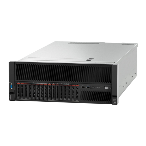
Chapter 1. Introduction The ThinkSystem SR860 is a 4U rack server designed for high-volume network transaction processing. This high-performance, multi-core server is ideally suited for networking environments that require superior processor performance, input/output (I/O) flexibility, and high manageability. Figure 1. ThinkSystem SR860 The server comes with a limited warranty. -
Page 10: Features
The Lenovo XClarity Controller consolidates multiple management functions in a single chip on the server system board. Some of the features that are unique to the Lenovo XClarity Controller are enhanced performance, higher- resolution remote video, and expanded security options. For additional information about the Lenovo XClarity Controller, refer to the XCC documentation compatible with your server at: https://sysmgt.lenovofiles.com/help/topic/lxcc_frontend/lxcc_overview.html... -
Page 11: Specifications
The server provides a QR code on the system service label, which is on the top cover of the server, that you can scan using a QR code reader and scanner with a mobile device to get quick access to the Lenovo Service Information website. - Page 12 • Eight 2.5-inch hot-swap SATA/SAS/NVMe drive bays (bay 4-7, 12-15) Drive backplane Two types of drive backplane: • 2.5-inch SATA/SAS 8-bay backplane (referred to as “8-bay backplane”) • 2.5-inch AnyBay 8-bay backplane (referred to as “AnyBay backplane”) ThinkSystem SR860 Setup Guide...
- Page 13 • Slot 1 - 2: PCI Express 3.0 for 4U PCIe riser card with the following slots available depending on the riser card installed in slot 3: – ThinkSystem SR860 2x8 PCIe FH riser 2 provides: – Slot 1: PCI Express 3.0 x8 –...
- Page 14 • One system-management RJ-45 connector on the rear to connect to a systems- management network. This connector is dedicated to the Lenovo XClarity Controller functions and runs at 1 GB speed. • Light-path diagnostics •...
- Page 15 Table 1. Specifications (7X69 and 7X70) (continued) Minimum configuration for • Two processors in processor sockets 1 and 2 debugging • Two memory DIMMs in slot 8 and 20 • One power supply • Six system fans (fan 1 to fan 6) •...
-
Page 16: Particulate Contamination
Table 1. Specifications (7X69 and 7X70) (continued) Environment ThinkSystem SR860 complies with ASHRAE class A2 specifications. Depending on the hardware configuration, some solution models comply with ASHRAE Class A3 or Class A4 specifications. System performance may be impacted when operating temperature is outside ASHRAE A2 specification or fan failed condition. -
Page 17: Management Options
If Lenovo determines that the levels of particulates or gases in your environment have caused damage to the device, Lenovo may condition provision of repair or replacement of devices or parts on implementation of appropriate remedial measures to mitigate such environmental contamination. - Page 18 Portable and light toolset for server configuration, data collection, and firmware updates. Suitable both for single-server or multi-server management contexts. Interface • OneCLI: CLI application Lenovo XClarity Essentials • Bootable Media Creator: CLI application, GUI application toolset • UpdateXpress: GUI application Usage and downloads http://sysmgt.lenovofiles.com/help/topic/xclarity_essentials/overview.html ThinkSystem SR860 Setup Guide...
- Page 19 Important: Lenovo XClarity Provisioning Manager (LXPM) supported version varies by product. All versions of Lenovo XClarity Provisioning Manager are referred to as Lenovo XClarity Provisioning Manager and LXPM in this document, unless specified otherwise. To see the LXPM version supported by your server, go to https:// sysmgt.lenovofiles.com/help/topic/lxpm_frontend/lxpm_product_page.html...
- Page 20 1. Most options can be updated through the Lenovo tools. Some options, such as GPU firmware or Omni- Path firmware require the use of supplier tools. 2. The server UEFI settings for option ROM must be set to Auto or UEFI to update firmware using Lenovo XClarity Administrator, Lenovo XClarity Essentials, or Lenovo XClarity Controller.
-
Page 21: Chapter 2. Server Components
Use the information in this section to learn about each of the components associated with your server. Identifying your server When you contact Lenovo for help, the machine type, model, and serial number information helps support technicians to identify your server and provide faster service. -
Page 22: Front View
Network activity LED (green) Drive activity LED (green) Identification button/LED (blue) Drive status LED (yellow) System error LED (yellow) USB 1 (USB 2.0 with Lenovo XClarity Controller Front operator panel with optional pull-out LCD management) display USB 2 Rack release latches Power button/LED (green) 2.5-inch drive bays... - Page 23 Identification button/LED (blue): Press this button to visually locate the server among other servers. Use this LED to visually locate the server among other servers. You can use Lenovo XClarity Controller to turn this LED on and off. System error LED (yellow): When this yellow LED is lit, it indicates that a system error has occurred.
-
Page 24: Front Operator Panel
When this yellow LED is lit, it indicates that a system error has occurred. This LED can be controlled by the Lenovo XClarity Administrator. Information provided from the LCD display of the front operator panel could also help isolate an error. -
Page 25: Front Operator Panel With Lcd Display
Front operator panel with LCD display The following section includes an overview of the LCD system information display panel of front operator panel, which displays various types of information about the server. Depends on the configuration, your front operator panel may come with a LCD display, which is accessible with a pull on the latch on the right of the front operator panel. - Page 26 Figure 9. System information on LCD display panel Table 6. System information display panel of front operator panel System name (ThinkSystem SR860) Checkpoint code Temperature (blinking in turns with System status Power consumption (blinking in turns with The option menu UI flow on the LCD display is illustrated as following.
- Page 27 Table 7. Options available on the front operator panel Option Description System error System error provides the total number of errors the system encountered, and the description of these errors. The information is displayed as following: System Has Encountered X Errors Whereas X is the total number of system errors encountered.
- Page 28 PS1 AC Voltage: YYY V PS2 AC Voltage: YYY V • Estimated power consumption is displayed as following: Sytem Power: ZZ W Whereas • XX is the temperature. • YYY is the AC voltage. • ZZ is the wattage. ThinkSystem SR860 Setup Guide...
-
Page 29: Rear View
Table 7. Options available on the front operator panel (continued) Actions Actions provides the following available actions, which come in effect by pressing and holding on the select button for three seconds: • Restore XCC default settings is displayed as following: RESTORE XCC DEFAULTS? HOLD v FOR 3s •... - Page 30 When this yellow LED is lit, it indicates that a system error has occurred. This LED can be controlled by the Lenovo XClarity Administrator. Information provided from the LCD display of the front operator panel could also help isolate an error.
- Page 31 Identification LED (blue): Use this LED to visually locate the server among other servers. You can use Lenovo XClarity Controller to turn this LED on and off. This LED is functionally equivalent to the identification LED on the front of the server.
- Page 32 • LOM adapter (slot 9): Insert LOM adapter into this slot (see “System-board connectors” in ThinkSystem SR860 Maintenance Manual for the location of the LOM adapter slot on the system board and “LOM adapter replacement” in ThinkSystem SR860 Maintenance Manual for information about the installation of the LOM adapter).
-
Page 33: Optional Processor And Memory Expansion Tray
PCIe slot 14 and 15 are available with a 4U PCIe riser card installed in slot 13. Following are the 4U PCIe riser cards supported by this server. – ThinkSystem SR860 2x8 PCIe FH riser 3 provides: – Slot 14: PCI Express 3.0 x8 –... - Page 34 DIMM slot 25-30 error LEDs Figure 15. Connectors on the optional processor and memory expansion tray Table 11. Connectors on the optional processor and memory expansion tray NVMe signal cable connector 0-1 NVMe signal cable connector 2-3 ThinkSystem SR860 Setup Guide...
-
Page 35: Pcie Riser Cards
PCIe riser cards Use this information to locate the connectors on the optional PCIe riser cards. x8/x8/x8 PCIe FH Riser Assembly Figure 16. x8/x8/x8 PCIe FH Riser Assembly Table 12. Components of x8/x8/x8 PCIe FH Riser Assembly PCIe full-height riser cage PCI Express 3.0 x8 (slot 6) PCI Express 3.0 x8 (slot 5) PCI Express 3.0 x8 (slot 7) -
Page 36: 2.5-Inch Drive Backplanes
Power/configuration cable connector 2.5-inch SATA/SAS 8-bay backplane comes with: • Eight SATA/SAS drive connectors with bay numbers of 0-7 or 8-15, depending on the location installed. • One power/configuration connector • Two SATA/SAS connectors (0, 1) ThinkSystem SR860 Setup Guide... -
Page 37: Raid Adapters
2.5-inch AnyBay (SATA/SAS/NVMe) 8-bay backplane Figure 20. 2.5-inch AnyBay (SATA/SAS/NVMe) 8-bay backplane Table 16. Connectors on 2.5-inch AnyBay (SATA/SAS/NVMe) 8-bay backplane SATA/SAS/NVMe connector 3 SATA/SAS connector 1 SATA/SAS/NVMe connector 2 SATA/SAS connector 0 SATA/SAS/NVMe connector 1 Power/configuration cable connector SATA/SAS/NVMe connector 0 Cable numbering labels 2.5-inch AnyBay (SATA/SAS/NVMe) 8-bay backplane comes with: •... -
Page 38: Internal Cable Routing
For more information about the requirements for cables and connecting devices, see the documentation that comes with these devices. Guideline for cable routing for 2.5-inch drives General guideline for cable routing for 2.5-inch drives. 1. Make sure all the signal cables go through the cable guides. ThinkSystem SR860 Setup Guide... - Page 39 Figure 24. Cable guide locations Table 20. Cable guide Cable guide Cable guide 2. If the processor and memory expansion tray is installed in the server, lift the tray and route the direct NVMe signal cables in the cable guide and behind the tray. Figure 25.
- Page 40 Power cable connector on the system board Power cable connector on the drive backplane Power cable connector on the system board Power cable connector on the drive backplane Two types of drive backplanes are supported by this system: ThinkSystem SR860 Setup Guide...
-
Page 41: Cable Routing For 2.5-Inch Drives To One
• 2.5-inch SATA/SAS 8-bay backplane (referred to as “8-bay backplane”) • 2.5-inch AnyBay 8-bay backplane (referred to as “AnyBay backplane”) 4U PCIe riser assemblies can be installed when the PCIe slot 3 or 13 are not occupied by PCIe adapters, make sure the slots for 4U PCIe riser cards are available before the riser card installation. - Page 42 One 8-bay backplane Figure 28. Cable routing, 8-bay backplane Table 22. Cables and adapters for routing SATA/SAS RAID adapter (8i) SATA/SAS signal cables (720 mm) ThinkSystem SR860 Setup Guide...
- Page 43 One AnyBay backplane Two processors installed Figure 29. Cable routing, AnyBay backplane with two processors installed Table 23. Cables and adapters for routing PCIe switch card NVMe signal cables for PCIe switch card SATA/SAS RAID adapter (8i) SATA/SAS signal cables (720 mm) Chapter 2 Server components...
-
Page 44: Backplanes
Following is the list of combinations of cable routing for 2.5-inch drives to two backplanes. • “Connecting signal cables to two backplanes” on page 38 – “8-bay backplane + 8-bay backplane” on page 38 – “AnyBay backplane + 8-bay backplane ” on page 40 – Two processors installed ThinkSystem SR860 Setup Guide... - Page 45 – Four processors installed – “AnyBay backplane + AnyBay backplane” on page 44 – Two processors installed – Four processors installed Chapter 2 Server components...
- Page 46 1. With SATA/SAS RAID adapter (16i) Figure 31. Cable routing, 8-bay backplane + 8-bay backplane Table 25. Cables and adapters for routing SATA/SAS RAID adapter (16i) SATA/SAS signal cables (720 mm) SATA/SAS signal cables (900 mm) ThinkSystem SR860 Setup Guide...
- Page 47 2. With SATA/SAS RAID adapter (8i) Figure 32. Cable routing, 8-bay backplane + 8-bay backplane Table 26. Cables and adapters for routing SATA/SAS RAID adapter (8i) SATA/SAS signal cables (720 mm) SATA/SAS RAID adapter (8i) SATA/SAS signal cables (720 mm) Chapter 2 Server components...
- Page 48 Figure 33. Cable routing, AnyBay backplane + 8-bay backplane Table 27. Cables and adapters for routing PCIe switch card SATA/SAS signal cables (720 mm) SATA/SAS RAID adapter (16i) SATA/SAS signal cables (900 mm) NVMe signal cables for PCIe switch card ThinkSystem SR860 Setup Guide...
- Page 49 2. With SATA/SAS RAID adapter (8i) Figure 34. Cable routing, AnyBay backplane + 8-bay backplane Table 28. Cables and adapters for routing PCIe switch card SATA/SAS signal cables (720 mm) SATA/SAS RAID adapter (8i) NVMe signal cables for PCIe switch card SATA/SAS RAID adapter (8i) SATA/SAS signal cables (720 mm) Chapter 2...
- Page 50 Table 29. Cables and adapters for routing SATA/SAS RAID adapter (16i) SATA/SAS signal cables (720 mm) NVMe connectors on the processor and memory SATA/SAS signal cables (900 mm) expansion tray Direct NVMe signal cables for processor and memory expansion tray ThinkSystem SR860 Setup Guide...
- Page 51 2. With SATA/SAS RAID adapter (8i) Figure 36. Cable routing, AnyBay backplane + 8-bay backplane Table 30. Cables and adapters for routing Direct NVMe signal cables for processor and SATA/SAS RAID adapter (8i) memory expansion tray NVMe connectors on the processor and memory SATA/SAS signal cables (720 mm) expansion tray SATA/SAS RAID adapter (8i)
- Page 52 Table 31. Cables and adapters for routing PCIe switch card NVMe signal cables for PCIe switch card SATA/SAS RAID adapter (16i) NVMe signal cables for PCIe switch card PCIe switch card SATA/SAS signal cables (720 mm) SATA/SAS signal cables (900 mm) ThinkSystem SR860 Setup Guide...
- Page 53 2. With SATA/SAS RAID adapter (8i) Figure 38. Cable routing, AnyBay backplane + AnyBay backplane Table 32. Cables and adapters for routing PCIe switch card SATA/SAS signal cables (720 mm) SATA/SAS RAID adapter (8i) NVMe signal cables for PCIe switch card SATA/SAS RAID adapter (8i) NVMe signal cables for PCIe switch card PCIe switch card...
- Page 54 SATA/SAS signal cables (900 mm) SATA/SAS RAID adapter (16i) SATA/SAS signal cables (720 mm) NVMe connectors on the processor and memory NVMe signal cables for PCIe switch card expansion tray Direct NVMe signal cables for processor and memory expansion tray ThinkSystem SR860 Setup Guide...
- Page 55 2. With SATA/SAS RAID adapter (16i) Figure 40. Cable routing, AnyBay backplane + AnyBay backplane Table 34. Cables and adapters for routing 4U PCIe riser card PCIe switch card SATA/SAS RAID adapter (16i) NVMe signal cables for PCIe switch card NVMe connectors on the processor and memory SATA/SAS signal cables (720 mm) expansion tray...
- Page 56 SATA/SAS RAID adapter (8i) SATA/SAS signal cables (720 mm) NVMe connectors on the processor and memory SATA/SAS signal cables (720 mm) expansion tray SATA/SAS RAID adapter (8i) NVMe signal cables for PCIe switch card ThinkSystem SR860 Setup Guide...
-
Page 57: Parts List
Use the parts list to identify each of the components that are available for your server. For more information about ordering the parts shown in Figure 43 “Server components” on page https://datacentersupport.lenovo.com/products/servers/thinksystem/sr860 Note: Depending on the model, your server might look slightly different from the illustration. Chapter 2... - Page 58 Figure 43. Server components The parts listed in the following table are identified as one of the following: ThinkSystem SR860 Setup Guide...
- Page 59 Tier 1 CRU at your request with no service agreement, you will be charged for the installation. • Tier 2 customer replaceable unit (CRU): You may install a Tier 2 CRU yourself or request Lenovo to install it, at no additional charge, under the type of warranty service that is designated for your server.
- Page 60 4U PCIe riser 2 power cable assembly √ 4U PCIe riser 3 power cable assembly √ PCIe expansion tray √ 4U PCIe riser assembly fillers √ 4U PCIe riser card x8 √ 4U PCIe riser card x16 √ Top cover √ ThinkSystem SR860 Setup Guide...
-
Page 61: Power Cords
Several power cords are available, depending on the country and region where the server is installed. To view the power cords that are available for the server: 1. Go to: http://dcsc.lenovo.com/#/ 2. Click Preconfigured Model or Configure to order. 3. Enter the machine type and model for your server to display the configurator page. - Page 62 ThinkSystem SR860 Setup Guide...
-
Page 63: Chapter 3. Server Hardware Setup
Validate that the server hardware was set up successfully. See “Validate server setup” on page 132. 3. Configure the system. a. Connect the Lenovo XClarity Controller to the management network. See “Set the network connection for the Lenovo XClarity Controller” on page 133. -
Page 64: Installation Guidelines
Go to to download firmware updates for your server. ThinkSystem SR860 Drivers and Software Important: Some cluster solutions require specific code levels or coordinated code updates. If the component is part of a cluster solution, verify that the latest level of code is supported for the cluster solution before you update the code. -
Page 65: System Reliability Guidelines
touch points on hot-swap components.) See the instructions for removing or installing a specific hot-swap component for any additional procedures that you might have to perform before you remove or install the component. • The Red strip on the drives, adjacent to the release latch, indicates that the drive can be hot-swapped if the server and operating system support hot-swap capability. -
Page 66: Handling Static-Sensitive Devices
Memory modules must be installed in a specific order based on the memory configuration that you implement and the number of processors and memory modules installed in the server. The following memory configurations and population sequences are supported for the ThinkSystem SR860 server: •... - Page 67 Independent memory mode In independent memory mode, memory channels can be populated with DIMMs in any order and you can populate all channels for each processor in any order with no matching requirements. Independent memory mode provides the highest level of memory performance, but lacks failover protection. The DIMM installation order for independent memory mode varies based on the number of processors and memory modules installed in the server.
- Page 68 The independent memory mode DIMM population sequences for each supported processor configuration are: • “Installation order: independent memory mode with two processors” on page 62 • “Installation order: independent memory mode with four processors” on page 63 ThinkSystem SR860 Setup Guide...
- Page 69 Chapter 3 Server hardware setup...
- Page 70 15 16 17 18 19 20 21 22 23 24 10 11 12 15 16 17 18 19 20 21 22 23 24 10 11 12 13 14 15 16 17 18 19 20 21 22 23 24 ThinkSystem SR860 Setup Guide...
- Page 71 Installation order: independent memory mode with four processors Memory module installation order for independent (non-mirroring) memory mode with four processors installed in the server. The following tables show the DIMM population sequence for independent memory mode when four processors are installed. •...
- Page 72 • To continue populating processor 3 and 4 DIMMs for a system with 25 to 48 DIMMs, see Table 45 “Independent mode with four processors (Processor 3 and 4, 25 to 48 total DIMMs installed in server)” on page ThinkSystem SR860 Setup Guide...
- Page 73 Table 44. Independent mode with four processors (Processor 3 and 4, 4 to 24 total DIMMs installed in server) Total Processor 3 Processor 4 Total DIMMs 25 26 27 28 29 30 31 32 33 34 35 36 37 38 39 40 41 42 43 44 45 46 47 48 DIMMs Related DIMM population sequences for four processor systems: •...
- Page 74 • To continue populating processor 1 and 2 DIMMs for a system with 25 to 48 DIMMs, see Table 43 “Independent mode with four processors (Processor 1 and 2, 25 to 48 total DIMMs installed in server)” on page ThinkSystem SR860 Setup Guide...
- Page 75 Memory mirroring Memory-mirroring mode provides full memory redundancy while reducing the total system memory capacity in half. Memory channels are grouped in pairs with each channel receiving the same data. If a failure occurs, the memory controller switches from the DIMMs on the primary channel to the DIMMs on the backup channel.
- Page 76 Memory mirroring DIMM population sequences for each of the supported processor configurations is shown by one of the following topics: • “Installation order: memory mirroring with two processors” on page 69 • “Installation order: memory mirroring with four processors” on page 70 ThinkSystem SR860 Setup Guide...
- Page 77 Installation order: memory mirroring with two processors Memory module installation order for memory mirroring with two processors installed in the server. The following table shows the DIMM population sequence for memory mirroring when two processors are installed. • Processors 1 and 2 are installed on the system board. Note: When adding one or more DIMMs during a memory upgrade, you might need to remove some DIMMs that are already installed to new locations.
- Page 78 19 20 21 22 23 24 Related DIMM population sequences for four processor systems: • To continue populating processor 3 and 4 DIMMs, see Table 51 “Memory mirroring with four processors (Processor 3 and 4)” on page ThinkSystem SR860 Setup Guide...
- Page 79 Table 51. Memory mirroring with four processors (processor 3 and 4) Total Processor 3 Processor 4 Total DIMMs 25 26 27 28 29 30 31 32 33 34 35 36 37 38 39 40 41 42 43 44 45 46 47 48 DIMMs 27 28 29 30 31 32 33 34 27 28 29 30...
- Page 80 Figure 48. Processor and memory module layout: processor 1 and 2 Table 52. Processor and memory module layout: processor 1 and 2 DIMM 1-6 DIMM 7-18 DIMM 19-24 Processor 1 Processor 2 ThinkSystem SR860 Setup Guide...
- Page 81 Figure 49. Processor and memory module layout: processor 3 and 4 Table 53. Processor and memory module layout: processor 3 and 4 Processor 3 DIMM 43-48 DIMM 31-42 DIMM 25-30 Processor 4 Table 54. Channel and slot information of DIMMs around a processor Slot Channel Channel 2...
- Page 82 ThinkSystem SR860 Setup Guide...
- Page 83 Installation order: memory sparing with two processors Memory module installation order for memory sparing with two processors installed in the server. The following table shows the DIMM population sequence for memory sparing when two processors are installed. • Processors 1 and 2 are installed on the system board. Notes: 1.
- Page 84 13 14 15 16 17 18 19 20 21 22 23 24 Related DIMM population sequences for four processor systems: • To continue populating processor 3 and 4 DIMMs, see Table 57 “Memory sparing with four processors (processor 3 and 4)” on page ThinkSystem SR860 Setup Guide...
-
Page 85: Dcpmm And Dram Dimm Installation Order
Table 57. Memory mirroring with four processors (processor 3 and 4) Total Processor 3 Processor 4 Total DIMMs 25 26 27 28 29 30 31 32 33 34 35 36 37 38 39 40 41 42 43 44 45 46 47 48 DIMMs 31 32 43 44 31 32... - Page 86 • All the DRAM DIMMs that are installed must be of the same type, rank, and capacity with minimum capacity of 16 GB. It is recommended to use Lenovo DRAM DIMMs of the same part number. • 64 GB 3DS LRDIMMs are not supported to be mixed with DCPMMs.
- Page 87 • All the DRAM DIMMs that are installed must be of the same type, rank, and capacity with minimum capacity of 16 GB. It is recommended to use Lenovo DRAM DIMMs of the same part number. 3. See “DCPMM and DRAM DIMM installation order” in Memory Population Reference to determine the new configuration, and acquire memory modules accordingly.
- Page 88 √ √ √ Other √ √ √ √ √ √ √ √ Other √ √ √ √ √ √ √ √ Other √ √ √ √ √ √ Other √ √ √ √ √ √ Other ThinkSystem SR860 Setup Guide...
- Page 89 Table 60. Memory population in App Direct Mode with two processors (not interleaved only) • D: DRAM DIMMs with 16 GB or larger capacity • P: DC Persistent Memory Module (DCPMM) Processor 1 Processor 2 Configuration 10 11 12 13 14 15 16 17 18 19 20 21 22 23 24 1 DCPMM and 12 DIMMs...
- Page 90 √ √ √ Other √ √ √ √ √ √ √ √ Other √ √ √ √ √ √ √ √ Other √ √ √ √ √ √ Other √ √ √ √ √ √ Other ThinkSystem SR860 Setup Guide...
- Page 91 Table 64. Memory population in App Direct Mode with four processors (not interleaved only) • D: DRAM DIMMs with 16 GB or larger capacity • P: DC Persistent Memory Module (DCPMM) Processor 1 Processor 2 Configuration 10 11 12 13 14 15 16 17 18 19 20 21 22 23 24 1 DCPMM and 24 DIMMs...
- Page 92 PMMs DIMMs √ √ √ √ √ √ √ √ Other √ √ √ √ √ √ √ √ Other √ √ √ √ √ √ √ Other √ √ √ √ √ √ √ Other ThinkSystem SR860 Setup Guide...
- Page 93 Installation order: Memory Mode with four processors Memory module installation order for DCPMM Memory Mode with four installed processors. Table 68. Memory population in Memory Mode with four processors • D1: DRAM DIMMs of 16 or 32 GB • D2: DRAM DIMMs of 32 GB or larger capacity •...
- Page 94 PMMs DIMMs √ √ √ √ √ √ √ √ Other √ √ √ √ √ √ √ √ Other √ √ √ √ √ √ √ Other √ √ √ √ √ √ √ Other ThinkSystem SR860 Setup Guide...
-
Page 95: Install Server Hardware Options
Installation order: Memory Mode with four processors Memory module installation order for DCPMM Memory Mode with four installed processors. Table 72. Memory population in Memory Mode with four processors • D1: DRAM DIMMs of 16 or 32 GB • D2: DRAM DIMMs of 32 GB or larger capacity •... -
Page 96: Remove The Security Bezel
Use the key to unlock the security bezel to the open position. Figure 50. Unlocking the security bezel Step 2. Press the release latch and pivot the security bezel outward to remove it from the chassis. ThinkSystem SR860 Setup Guide... -
Page 97: Remove The Top Cover
Figure 51. Security bezel removal Remove the top cover Use this procedure to remove the top cover. S014 CAUTION: Hazardous voltage, current, and energy levels might be present. Only a qualified service technician is authorized to remove the covers where the label is attached. S033 CAUTION: Hazardous energy present. -
Page 98: Remove A 4U Pcie Riser Assembly
Remove a 4U PCIe riser assembly Use this procedure to remove a 4U PCIe riser assembly. Before removing a 4U PCIe riser assembly: 1. Read the safety information and installation guidelines (see “Safety” on page iii “Installation Guidelines” on page 56). ThinkSystem SR860 Setup Guide... - Page 99 2. Turn off the server and peripheral devices and disconnect the power cords and all external cables (see “Power off the server” on page 132). 3. If the server is installed in a rack, remove the server from the rack. 4.
-
Page 100: Remove The Pcie Expansion Tray
4. Remove the top cover (see “Remove the top cover” on page 89). To remove the PCIe expansion tray, complete the following steps: Watch the procedure A video of this procedure is available at YouTube: https://www.youtube.com/watch?v=pIb0bIyfkDY&= PLYV5R7hVcs-Ak9fT8QAx8fLbEivizjRtp ThinkSystem SR860 Setup Guide... -
Page 101: Remove The Chassis Air Baffle
Figure 55. PCIe expansion tray removal Step 1. Remove all the 4U PCIe riser assemblies and the 4U PCIe riser assembly fillers that are installed in the PCIe expansion tray (see “Remove a 4U PCIe riser assembly” on page 90). Step 2. -
Page 102: Remove The System Board Air Baffle And The Power Interposer
Use this procedure to remove the system board air baffle and the power interposer. Note: If the server comes with a processor and memory expansion tray, it does not come with this component. Before removing the system board air baffle, complete the following steps: ThinkSystem SR860 Setup Guide... - Page 103 PLYV5R7hVcs-Ak9fT8QAx8fLbEivizjRtp Step 1. Slightly slide power supply 2 out from the power supply bay (see “Remove a hot-swap power supply unit” in ThinkSystem SR860 Maintenance Manual). Step 2. Lift the power interposer from the server, and set it aside. Figure 57. Power interposer removal Step 3.
-
Page 104: Remove The Processor And Memory Expansion
6. If you are replacing the processor and memory expansion tray, remove the processor and memory expansion tray air baffle, DIMMs (see Remove a DIMM), and PHMs (see “Remove a processor and the heatsink” in ThinkSystem SR860 Maintenance Manual) on the expansion tray. ThinkSystem SR860 Setup Guide... - Page 105 Figure 59. Processor and memory expansion tray air baffle removal Attention: Do not remove or install DIMMs and processors on the processor and memory expansion tray when the expansion tray is removed, for the instability might cause damages to components. To remove the processor and memory expansion tray, complete the following steps: Watch the procedure A video of this procedure is available at YouTube:...
-
Page 106: Remove The Fan Cage Assembly
The device also might have more than one power cord. To remove all electrical current from the device, ensure that all power cords are disconnected from the power source. S017 ThinkSystem SR860 Setup Guide... - Page 107 CAUTION: Hazardous moving fan blades nearby. Keep fingers and other body parts away. Before removing the fan cage assembly: 1. Read the safety information and installation guidelines (see “Safety” on page iii “Installation Guidelines” on page 56). 2. Turn off the server and peripheral devices and disconnect the power cords and all external cables (see “Power off the server”...
- Page 108 ThinkSystem SR860 Setup Guide...
-
Page 109: Install A Processor-Heat-Sink Module
• PHMs are keyed for the socket where they can be installed and for their orientation in the socket. • See https://static.lenovo.com/us/en/serverproven/index.shtml for a list of processors supported for your server. All processors on the system board must have the same speed, number of cores, and frequency. - Page 110 Remove the processor socket cover, if one is installed on the processor socket, by placing your fingers in the half-circles at each end of the cover and lifting it from the system board. Step 2. Install the processor-heat-sink module on the system board. ThinkSystem SR860 Setup Guide...
- Page 111 Figure 63. Installing a PHM Align the triangular marks and guide pins on the processor socket with the PHM; then, insert the PHM into the processor socket. Attention: To prevent damage to components, make sure that you follow the indicated tightening sequence.
-
Page 112: Install A Memory Module
Before installing a memory module, make sure that you understand the required installation order, depending on whether you are implementing memory mirroring, memory rank sparing, or independent memory mode. See ThinkSystem SR860 Memory Population Reference for the required installation order. If you are installing an optional processor, install it before installing memory modules. See “Install a... -
Page 113: Install A Drive Backplane
6. If you have installed a DCPMM, make sure the DCPMM firmware is the latest version. If not, update it to the latest version (see https://sysmgt.lenovofiles.com/help/topic/com.lenovo.lxca.doc/update_fw.html 7. Configure DCPMMs and DRAM DIMMs (see “Configure Persistent Memory Module (PMem)” on page 139). - Page 114 Apply this label to drive bay 12-15 if an 8-bay backplane is installed to drive bay 8-15 – 4-7 Apply this label to drive bay 4-7 if an 8-bay backplane is installed to drive bay 0-7. ThinkSystem SR860 Setup Guide...
-
Page 115: Install A 2.5-Inch Hot-Swap Drive
• AnyBay backplane – 4-7 (NVMe) Apply this label to drive bay 4-7 if an AnyBay backplane is installed to drive bay 0-7. – 12-15 (NVMe) Apply this label to drive bay 12-15 if an AnyBay backplane is installed to drive bay 8-15. Note: Only drive bay 4-7 and 12-15 may support NVMe solid-state drives when the AnyBay backplane is installed. - Page 116 Remove the drive bay filler if it has been installed in the drive bay. Step 3. Gently rotate the release latch away to unlock the drive handle. Step 4. Slide the drive into the drive bay, and push it until it stops. ThinkSystem SR860 Setup Guide...
-
Page 117: Install The Fan Cage Assembly
Figure 68. Drive installation Step 5. Rotate the drive-tray handle back to the locked position. After installing the 2.5-inch hot-swap drive, check the drive status LED to verify if the drive is operating correctly: • If the yellow LED is lit continuously, it is malfunctioning and must be replaced. •... -
Page 118: Install The System Board Air Baffle And The Power Interposer
A video of this procedure is available at YouTube: https://www.youtube.com/watch?v=pIb0bIyfkDY&= PLYV5R7hVcs-Ak9fT8QAx8fLbEivizjRtp Step 1. Slightly slide power supply 2 out from the power supply bay (see “Remove a hot-swap power supply unit” in ThinkSystem SR860 Maintenance Manual). ThinkSystem SR860 Setup Guide... - Page 119 Step 2. Align the power interposer to the server, and lower it until it sits firmly in place. Figure 70. Power interposer installation Step 3. Align the two pairs of nailheads of the system board air baffle to slots, and lower it into the server. Attention: Air baffle is required for airflow that creates proper cooling.
-
Page 120: Install The Processor And Memory Expansion Tray
(s) for system configuration is installed before the power is turned on. Step 3. Slightly slide power supply 2 out from the power supply bay (see “Remove a hot-swap power supply unit” in ThinkSystem SR860 Maintenance Manual). ThinkSystem SR860 Setup Guide... - Page 121 Step 4. Grip on the blue touch point on the handle of the expansion tray, and lift it up; then, lower the tray vertically into the server with nailheads aligned to the slots on both sides. Step 5. Rotate the handle down to make sure the expansion tray is fully seated into the system board. Figure 73.
-
Page 122: Install The Pcie Riser Card Assembly
After installing the processor and memory expansion tray, complete the following steps: 1. Reinstall power supply 2 (see “Install hot-swap power supply” in ThinkSystem SR860 Maintenance Manual). 2. Install the PCIe expansion tray (see “Install the PCIe expansion tray”... - Page 123 Figure 75. Removing USB 3.0 connector vertically To install the PCIe riser card assembly, complete the following steps: Watch the procedure A video of this procedure is available at YouTube: https://www.youtube.com/watch?v=pIb0bIyfkDY&= PLYV5R7hVcs-Ak9fT8QAx8fLbEivizjRtp Step 1. Assemble the PCIe riser card assembly: Align the bottom of the PCIe riser card to the slot, and rotate the top to fit it into the slot on the riser-cage;...
- Page 124 Figure 78. PCIe riser card assembly installation Step 3. Reconnect all the cables disconnected previously. After installing the PCIe riser card assembly, complete the following steps: 1. Reconnect the USB 3.0 cable of operator panel tray assembly vertically to the system board. ThinkSystem SR860 Setup Guide...
- Page 125 Figure 79. Installing USB 3.0 connector vertically Route the USB 3.0 cable in the cable guide and away from the PCIe slots area (marked in gray). Figure 80. Routing USB 3.0 cable USB 3.0 connector 2. Install the PCIe expansion tray (see “Install the PCIe expansion tray”...
-
Page 126: Install The Lom Adapter
4. Attach the mounting bracket with the two screws as illustrated. Figure 81. LOM adapter assembly To install the LOM adapter, complete the following steps: Watch the procedure A video of this procedure is available at YouTube: https://www.youtube.com/watch?v=pIb0bIyfkDY&= PLYV5R7hVcs-Ak9fT8QAx8fLbEivizjRtp ThinkSystem SR860 Setup Guide... -
Page 127: How To Adjust The Position Of The Retainer On The M.2 Backplane
Step 1. Open the retention latch. Step 2. Align the LOM adapter to the connector, and push it in. Step 3. Tighten the captive thumbscrew to lock it to the connector. Figure 82. LOM adapter installation Step 4. Close the retention latch. After installing the LOM adapter, complete the following steps: 1. -
Page 128: Install An M.2 Drive In The M.2 Backplane
• Install the M.2 drive in slot 0 first. Figure 84. M.2 drive slot Table 80. M.2 drive slot Slot 0 Slot 1 Step 1. Locate the connector on each side of the M.2 backplane. ThinkSystem SR860 Setup Guide... -
Page 129: Install The M.2 Backplane
Step 2. Insert the M.2 drive at an angle (approximately 30 degrees) into the connector and rotate it until the notch catches on the lip of the retainer; then, slide the retainer forward (toward the connector) to secure the M.2 drive in the M.2 backplane. Figure 85. - Page 130 T-head pins on the hard drive cage; then, insert the backplane in the system board connector. Press down on the M.2 backplane to fully seat Figure 88. M.2 backplane installation ThinkSystem SR860 Setup Guide...
-
Page 131: Install The Chassis Air Baffle
After installing the M.2 backplane, complete the following steps: 1. Reinstall the PCIe riser card if necessary (see “Install the PCIe riser card assembly” on page 114). 2. Reinstall the LOM adapter if necessary (see “Install the LOM adapter” on page 118). -
Page 132: Install The Pcie Expansion Tray
Grasp the handle with one of your hands, with the other hand grasping the PCIe expansion tray lift point; then, carefully lower the tray into the server. Make sure the four posts on the sides are inserted into the alignment slots on the chassis. ThinkSystem SR860 Setup Guide... - Page 133 Figure 90. PCIe expansion tray installation Step 2. Slightly press on the PCIe expansion tray into the server until all the nailheads on the side the rear of the tray seat into the slots on the top of the chassis. Step 3.
-
Page 134: Install A 4U Pcie Riser Assembly
Watch the procedure A video of this procedure is available at YouTube: https://www.youtube.com/watch?v=pIb0bIyfkDY&= PLYV5R7hVcs-Ak9fT8QAx8fLbEivizjRtp Step 1. Remove the PCIe expansion tray (see “Remove the PCIe expansion tray” on page 92) to install the PCIe connector guide. ThinkSystem SR860 Setup Guide... - Page 135 Figure 92. 4U PCIe riser assembly installation Step 2. Reinstall the PCIe expansion tray (see “Install the PCIe expansion tray” on page 124) and remove the 4U PCIe riser assembly fillers if any are installed. Step 3. Align the 4U PCIe riser assembly with the rear chassis and the guide pins on the side of the PCIe expansion tray;...
-
Page 136: Install The Top Cover
2. If the server is installed in a rack, reinstall the server into the rack. 3. Power on the server and any peripheral devices. Install the top cover Use this procedure to install the server top cover. S014 ThinkSystem SR860 Setup Guide... - Page 137 CAUTION: Hazardous voltage, current, and energy levels might be present. Only a qualified service technician is authorized to remove the covers where the label is attached. S033 CAUTION: Hazardous energy present. Voltages with hazardous energy might cause heating when shorted with metal, which might result in spattered metal, burns, or both.
-
Page 138: Install The Security Bezel
“Installation Guidelines” on page 56). 2. If you have removed the rack handles, reinstall it (see ThinkSystem SR860 Rack Installation Guide). To install the security bezel, complete the following steps: Watch the procedure A video of this procedure is available at YouTube: https://www.youtube.com/watch?v=pIb0bIyfkDY&=... -
Page 139: Install The Server In A Rack
• You can press the power button. • The server can restart automatically after a power interruption. • The server can respond to remote power-on requests sent to the Lenovo XClarity Controller. For information about powering off the server, see “Power off the server”... -
Page 140: Validate Server Setup
Power off the server The server remains in a standby state when it is connected to a power source, allowing the Lenovo XClarity Controller to respond to remote power-on requests. To remove all power from the server (power status LED off), you must disconnect all power cables. -
Page 141: Chapter 4. System Configuration
The following methods are available to set the network connection for the Lenovo XClarity Controller if you are not using DHCP: • If a monitor is attached to the server, you can use Lenovo XClarity Provisioning Manager to set the network connection. -
Page 142: Update The Firmware
Controller Network Access label that is affixed to the Pull Out Information Tab. • If you are using the Lenovo XClarity Administrator Mobile app from a mobile device, you can connect to the Lenovo XClarity Controller through the Lenovo XClarity Controller USB connector on the front of the server. - Page 143 Hat Enterprise Linux (RHEL) and SUSE Linux Enterprise Server (SLES) operating system distributions. Machine-type-specific firmware-only UXSPs are also available. Firmware updating tools See the following table to determine the best Lenovo tool to use for installing and setting up the firmware: Tool Update...
- Page 144 • Lenovo XClarity Controller If you need to install a specific update, you can use the Lenovo XClarity Controller interface for a specific server. Notes: – To perform an in-band update through Windows or Linux, the operating system driver must be installed and the Ethernet-over-USB (sometimes called LAN over USB) interface must be enabled.
-
Page 145: Configure The Firmware
Several options are available to install and set up the firmware for the server. Important: Do not configure option ROMs to be set to Legacy unless directed to do so by Lenovo Support. This setting prevents UEFI drivers for the slot devices from loading, which can cause negative side effects for Lenovo software, such as Lenovo XClarity Administrator and Lenovo XClarity Essentials OneCLI, and to the Lenovo XClarity Controller. -
Page 146: Memory Configuration
In addition, you can choose to make the text-based interface the default interface that is displayed when you start LXPM. To do this, go to Lenovo XClarity Provisioning Manager ➙ UEFI Setup ➙ System Settings ➙ <F1>Start Control ➙ Text Setup. To start the server with Graphic User Interface, select Auto or Tool Suite. -
Page 147: Configure Persistent Memory Module (Pmem)
If a password has been set, enter the password to unlock LXPM. Go to UEFI Setup ➙ System Settings ➙ Intel Optane PMems to configure and manage PMems. For more details, see the “UEFI Setup” section in the Lenovo XClarity Provisioning Manager documentation version compatible with your server at https://sysmgt.lenovofiles.com/help/topic/lxpm_... - Page 148 Note: If the text-based interface of Setup Utility opens instead of Lenovo XClarity Provisioning Manager, go to System Settings ➙ <F1> Start Control and select Tool Suite. Then, reboot the system and press the key specified in the on-screen instructions as soon as the logo screen appears to open Lenovo XClarity Provisioning Manager.
- Page 149 These values are selectable options for PMem settings, and do not represent the current PMem status. In addition, you can take advantage of a memory configurator, which is available at the following site: http://1config.lenovo.com/#/memory_configuration Alternatively, set PMem Goals with the following commands in OneCLI: 1. Set create goal status.
- Page 150 --imm USERID:PASSW0RD@10.104.195.86 Where 123456 stands for the passphrase. 3. Reboot the system. • Disable security: 1. Disable security. onecli.exe config set IntelOptanePMEM.SecurityOperation "Disable Security" --imm USERID:PASSW0RD@10.104.195.86 2. Enter passphrase. onecli.exe config set IntelOptanePMEM.SecurityPassphrase "123456" --imm USERID:PASSW0RD@10.104.195.86 ThinkSystem SR860 Setup Guide...
- Page 151 In the case the passphrases are lost or forgotten, the stored data cannot be backed up or restored, but you can contact Lenovo service for administrative secure erase. • After three failed unlocking attempts, the corresponding PMems enter “exceeded” state with a system warning message, and the PMem unit can only be unlocked after the system is rebooted.
-
Page 152: Raid Configuration
OS logical drives or volumes. An introduction to RAID is available at the following Lenovo Press website: https://lenovopress.com/lp0578-lenovo-raid-introduction Detailed information about RAID management tools and resources is available at the following Lenovo Press website: https://lenovopress.com/lp0579-lenovo-raid-management-tools-and-resources Deploy the operating system Several options are available to deploy an operating system on the server. -
Page 153: Back Up The Server Configuration
– Lenovo XClarity Essentials OneCLI http://sysmgt.lenovofiles.com/help/topic/toolsctr_cli_lenovo/onecli_r_uxspi_proxy_tool.html – Lenovo XClarity Integrator deployment pack for SCCM (for Windows operating system only) https://sysmgt.lenovofiles.com/help/topic/com.lenovo.lxci_deploypack_sccm.doc/dpsccm_c_endtoend_ deploy_scenario.html Manual deployment If you cannot access the above tools, follow the instructions below, download the corresponding OS Installation Guide, and deploy the operating system manually by referring to the guide. -
Page 154: Uuid
2. Copy and unpack the OneCLI package, which also includes other required files, to the server. Make sure that you unpack the OneCLI and the required files to the same directory. 3. After you have Lenovo XClarity Essentials OneCLI in place, type the following command to set the UUID: onecli config set SYSTEM_PROD_DATA.SysInfoUUID <uuid_value>... -
Page 155: Update The Asset Tag
• From Lenovo XClarity Provisioning Manager To update the asset tag from Lenovo XClarity Provisioning Manager: 1. Start the server and press the key specified in the on-screen instructions to display the Lenovo XClarity Provisioning Manager interface. 2. If the power-on Administrator password is required, enter the password. - Page 156 3. After you have Lenovo XClarity Essentials OneCLI in place, type the following command to set the DMI: onecli config set SYSTEM_PROD_DATA.SysEncloseAssetTag <asset_tag> [access_method] Where: <asset_tag> The server asset tag number. Type asset aaaaaaaaaaaaaaaaaaaaaaaaaaaaaaaaa, where aaaaaaaaaaaaaaaaaaaaaaaaaaaaaaaaa is the asset tag number.
-
Page 157: Chapter 5. Resolving Installation Issues
“Displayed system memory is less than installed physical memory” on page 151 • “A Lenovo optional device that was just installed does not work.” on page 152 Server does not power on Complete the following steps until the problem is resolved: Note: The power-control button will not function until approximately 5 to 10 seconds after the server has been connected to power. - Page 158 7. If you just installed an optional device, remove it, and restart the server. If the server now starts, you might have installed more devices than the power supply supports. 8. See “Power supply LEDs” in ThinkSystem SR860 Maintenance Manual. The server immediately displays the POST Event Viewer when it is turned on Complete the following steps until the problem is solved.
- Page 159 • If the green activity LED is flashing and the yellow status LED is flashing slowly, the drive is recognized by the controller and is rebuilding. • If neither LED is lit or flashing, check whether the hard disk drive backplane is correctly seated. For details, go to step 4.
- Page 160 2 (if installed) to verify that the problem is not the processor or the memory module connector. 8. (Trained technician only) Replace the system board. A Lenovo optional device that was just installed does not work. 1. Make sure that: •...
- Page 161 3. Replace the device that you have just installed. 4. Reseat the cable connection and check there is no physical damage to the cable. 5. If there is any cable damages, then replace the cable. Chapter 5 Resolving installation issues...
- Page 162 ThinkSystem SR860 Setup Guide...
-
Page 163: Assistance
Appendix A. Getting help and technical assistance If you need help, service, or technical assistance or just want more information about Lenovo products, you will find a wide variety of sources available from Lenovo to assist you. On the World Wide Web, up-to-date information about Lenovo systems, optional devices, services, and support are available at: http://datacentersupport.lenovo.com... -
Page 164: Collecting Service Data
Collecting service data To clearly identify the root cause of a server issue or at the request of Lenovo Support, you might need collect service data that can be used for further analysis. Service data includes information such as event logs and hardware inventory. -
Page 165: Appendix A. Getting Help And Technical Contacting Support
• Lenovo XClarity Essentials OneCLI Lenovo XClarity Essentials OneCLI has inventory application to collect service data. It can run both in- band and out-of-band. When running in-band within the host operating system on the server, OneCLI can collect information about the operating system, such as the operating system event log, in addition to the hardware service data. - Page 166 ThinkSystem SR860 Setup Guide...
-
Page 167: Index
Ethernet activity remove collecting service data Ethernet adapter slot, 10 Gb Common installation issues Configuration - ThinkSystem SR860 configure the firmware connecting drive cables connector Ethernet systems-management fan cage Lenovo XClarity Controller install power supply... - Page 168 LCD system information display panel ac power 21–22 dc power 21–22 Ethernet-link status NMI button for Ethernet activity on the light path diagnostics panel for hard disk drive activity non-mirroring memory mode for hard disk drive status DIMM installation order ThinkSystem SR860 Setup Guide...
- Page 169 System information LED rear system board air baffle power-on LED install power-supply LED 21–22 remove presence detection button System configuration - ThinkSystem SR860 processor system reliability guidelines option install system-identification processor and memory expansion tray button install rear remove processor-heat-sink module...
- Page 170 21, 23 power on ThinkSystem SR860 Setup Guide...
- Page 172 Part Number: SP47A30799 Printed in China (1P) P/N: SP47A30799 *1PSP47A30799*...
Need help?
Do you have a question about the ThinkSystem SR860 and is the answer not in the manual?
Questions and answers