Table of Contents

Subscribe to Our Youtube Channel
Related Manuals for ZyXEL Communications RGS Series


Summary of Contents for ZyXEL Communications RGS Series
- Page 1 RGS Series Rugged Switch Series Version 1 Edition 3, 07/2019 Hardware and Web User’s Guide Default Login Details LAN IP Address http://192.168.1.1 User Name admin Password 1234 Copyright © 2019 Zyxel Communications Corporation...
- Page 2 IMPORTANT! READ CAREFULLY BEFORE USE. KEEP THIS GUIDE FOR FUTURE REFERENCE. This is a User’s Guide for a series of products. Not all products support all firmware features. Screenshots and graphics in this book may differ slightly from your product due to differences in your product firmware or your computer operating system.
-
Page 3: Table Of Contents
Top Panel Introduction ....................12 Quick Installation ......................14 Mounting the RGS Series (DIN-Rail) ................14 Mounting the RGS Series (Wall mount) ................15 Ground Connections ...................... 16 Connecting the Ethernet Interface (RJ45 Ethernet) ............19 Connecting the Ethernet Interface (Fiber) ............... 20 Power Connection ...................... - Page 4 5.3.6 System Alarm Profile ..................45 5.3.7 EEE – Port Power Savings ................47 5.3.8 Port ........................49 5.3.9 DHCP Snooping ....................50 5.3.10 DHCP Relay ...................... 51 5.3.11 Security – Switch Users ..................53 5.3.12 Privilege Level ....................54 5.3.13 Authentication Method ..................
- Page 5 5.3.57 Port Filtering Profile ..................130 5.3.58 LLDP – LLDP Configuration ................131 5.3.59 LLDP-MED ...................... 133 5.3.60 PoE ......................... 137 5.3.61 PoE Scheduler ....................139 5.3.62 Power Reset ....................140 5.3.63 MAC Table ....................... 141 5.3.64 VLANs ......................142 5.3.65 Voice VLAN –...
- Page 6 5.4.24 Switch – RMON Statistics ................197 5.4.25 History ......................199 5.4.26 Alarm ....................... 200 5.4.27 Event ....................... 201 5.4.28 LACP System Status ..................202 5.4.29 Port Status ...................... 203 5.4.30 Port Statistics ....................204 5.4.31 Loop Protection ....................205 5.4.32 Spanning Tree –...
- Page 7 Preface Scope Audience Safety Instructions Documentation Conventions...
-
Page 8: Preface
1. Preface 1.1 Scope This document provides an overview on RGS200-12P. It contains: • Descriptive material about the RGS200-12P Hardware Installation Guide. 1.2 Audience The guide is intended for system engineers or operating personnel who want to have a basic understanding of RGS200-12P. - Page 9 Overview Overview Faceplate Panel Introduction...
-
Page 10: Overview
2. Overview RGS Series industrial Ethernet solutions deliver high quality, wide operation temperature range, extended power input range and advanced VLAN & QoS features. It’s ideal for harsh environments and mission critical applications. 2.1 Faceplate 5-Port Series... -
Page 11: Front Panel Introduction
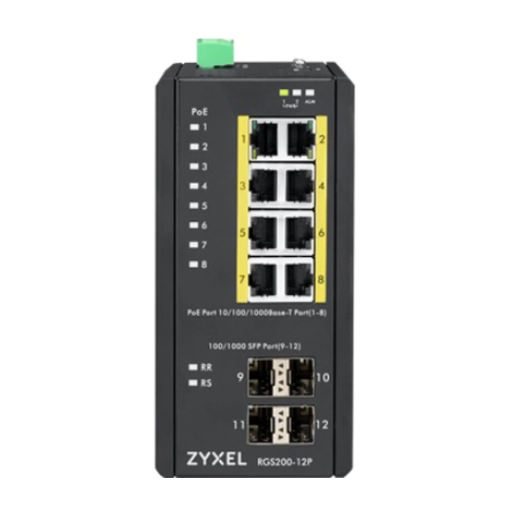
12-Port Series 2.2 Front Panel Introduction Front Panel System Status LED P1, P2 and Alarm Gigabit Ethernet Copper Ports RJ45 Gigabit Ethernet SFP ports SFP Slots POE LED POE port status RR/RS LED Device info/status L2+ Managed Switch Models RGS200-12P Total Gigabit Ethernet Ports 10/100/1000 BaseT(X) -
Page 12: Top Panel Introduction
2.3 Top Panel Introduction Top Panel Power Input (Dual) 6P Terminal Block Console (RS232) RJ45 Reset Push Button... - Page 13 Quick Installation Equipment Mounting Cable Connecting Equipment Configuration...
-
Page 14: Quick Installation
3.Quick Installation 3.1 Mounting the RGS Series (DIN-Rail) Mounting step: 1. Screw the DIN-Rail bracket on with the bracket and screws in the accessory kit. 2. Hook the unit over the DIN rail. 3. Push the bottom of the unit towards the DIN Rail until it snaps into place. -
Page 15: Mounting The Rgs Series (Wall Mount)
3.2 Mounting the RGS Series (Wall mount) The Switch can be mounted on a wall. You may need screw anchors if mounting on a concrete or brick wall. 2.3.1 Installation Requirements • Distance above the floor: At least 1.8 m (5.9 feet) •... -
Page 16: Ground Connections
Figure 3 RGS100-5P Series Wall Mounting Figure 4 RGS200-12P Series Wall Mounting 3.3 Ground Connections RGS Series must be properly grounded for optimum system performance. - Page 17 Grounding is a safety measure to have unused electricity return to the ground. It prevents damage to the Switch, and protects you from electrocution. Any device that is located outdoors and connected to this product must be properly grounded and surge protected.
- Page 18 Figure 6 RGS200-12P Series Ground Connections...
-
Page 19: Connecting The Ethernet Interface (Rj45 Ethernet)
To connect the switch to an Ethernet device, use UTP (Unshielded Twisted Pair) or STP (Shielded Twisted Pair) Ethernet cables. The pin assignment of RJ-45 connector is shown in the following figure and table. The pin assignment of RJ-45 connector is shown in the following figure and table. RGS Series Assignment T/Rx+,T/Rx- T/Rx+,T/Rx-... -
Page 20: Connecting The Ethernet Interface (Fiber)
3.5 Connecting the Ethernet Interface (Fiber) Prepare a proper SFP module and install it into the optical port. Then you can connect fiber optics cabling that uses LC connectors or SC connectors (with the use of an optional SC-to-LC adapter) to the fiber optics connector. -
Page 21: Power Connection
3.6 Power Connection The DC power interface is a 6-pin terminal block with polarity signs on the top panel. The RGS200-12P can be powered from two power supply (input range 12V – 58V). The DC power connector is a 6-pin terminal block; there is alarm contact on the middle terminal block. Refer to Table 1 for the normal operational LED status. -
Page 22: Console Connection
3.7 Console Connection The Console port is for local management by using a terminal emulator or a computer with terminal emulation software. • DB9 connector connect to computer COM port • Baud rate: 115200bps • 8 data bits, 1 stop bit •... -
Page 23: System Reset
3.8 System Reset The Reset button is provided to reboot the system without the need to remove power. Under normal circumstances, you will not have to use it. However, or rare occasions, the RGS200-12P may not respond; then you may need to push the Reset button. Reset Button 3.9 Web Interface Initialization (Optional) Web Browser Support... - Page 24 Google Chrome with the following default settings is recommended: Web page font Times New Roman Encoding Unicode (UTF-8) Text size Medium Connect and Login to RGS200-12P Connecting to RGS200-12P Ethernet port (RJ45 Ethernet port). Factory default IP: 192.168.1.1 Login with default account and password. Username: admin Password: 1234...
-
Page 25: Cli Initialization And Configuration (Optional)
3.10 CLI Initialization and Configuration (Optional) Connecting to RGS200-12P Ethernet port(RJ45 Ethernet port) Key-in the command under Telnet: telnet 192.168.1.1 Login with default account and password. Username: admin Password: 1234 Change the IP with commands listed below: CLI Command: enable configure terminal interface vlan 1 ip address xxx.xxx.xxx.xxx xxx.xxx.xxx.xxx... -
Page 26: Monitoring The Ethernet Interface
3.11 Monitoring the Ethernet Interface By RJ45 Ethernet: Refer to Figure 11 LED Indicators for monitoring 8 Gigabit Ethernet with copper connector (RJ45). Also refer toTable 1 for the normal operational LED status. By SFP: Refer to Figure 11 LED Indicators for monitoring 4 Gigabit Ethernet with SFP connector. Also refer to Table 1 for the normal operational LED status. -
Page 27: Reset To Default And Save Configure
3.13 Reset to Default and Save Configure Configuration via CLI command To see what current interface and IP address is: If the manager wants to reset the configuration to default, but keep management IP setting. (1) Please execute this command: reload defaults keep-ip (2) Check interface VLAN and IP address;... - Page 28 Configuration via WEB UI If manager want to reset the configuration to default but keep management IP setting (1)Go to “Maintenance””Factory Defaults” pagination to Click “Yes” button. (2) Go to “Maintenance” “Configuration””Save startup-config” pagination, then click “Save Configuration” button, then reset successfully If manager want to reset the all configuration to default completely (1) Go to “Maintenance”...
- Page 29 (2) Change WEB’s IP be 192.0.2.1(default IP) to login DUT’s Web UI. (3) Go to “Maintenance” “Configuration””Save startup-config” pagination, then click “Save Configuration” button, then reset successfully.
-
Page 30: Dip Switch Setting For Rgs100-5P
3.14 DIP Switch Setting for RGS100-5P Pin No# Status 5-Port (4TX+1SFP) with PoE Pin 1 To enable Broadcast storm rate limit To disable Broadcast storm rate limit Pin 2 NOT USED NOT USED 3.15 LED Status Indications Table 1 LED Status Indicators Indicator Condition Name... - Page 31 PWR LED Indicator LED Indicator Copper Link/Act LED Copper Speed LED SFP Link LED Indicator SFP Speed LED Indicator LED Indicators Figure 11...
-
Page 32: Introduction
RGS Series Managed QoS provides enterprise-class networking features to fulfill the needs of large network infrastructure and extreme environments. RGS Series eases the effort to build a network infrastructure which offers a reliable, well managed and good QoS networking for any business requiring continuous and well-protected services in management environments. -
Page 33: Navigation
Text size Medium 4.2.2 Navigation All main screens of the web interface can be reached by clicking on hyperlinks in the four menu boxes on the left side of the screen: Configuration Monitor Diagnostics Maintenance 4.2.3 Title Bar Icons Help Button For more information about any screen, click on the Help button on the screen. -
Page 34: Using The Online Help
4.3 Using the Online Help Each screen has a Help button that invokes a page of information relevant to the particular screen. The Help is displayed in a new window. Each web page of Configuration/Status/System functions has a corresponding help page. -
Page 35: Using The Web
5. Using the Web 5.1 Login Operation Fill Username and Password Click “Sign in” Field Description Username Login user name. The maximum length is 32. Default: admin Password Login user password. The maximum length is 32. Default: none 5.2 Tree View The tree view is a menu of the web. -
Page 36: Configuration Menu
5.2.1 Configuration Menu... -
Page 37: Monitor Menu
5.2.2 Monitor Menu... -
Page 38: Diagnostics Menu
5.2.3 Diagnostics Menu 5.2.4 Maintenance Menu... -
Page 39: Configuration
5.3 Configuration 5.3.1 System Information The switch system information is provided here. Object Description System Contact The textual identification of the contact person for this managed node, together with information on how to contact this person. The allowed string length is 0 to 255, and the allowed content is the ASCII characters from 32 to 126. -
Page 40: System Ip
5.3.2 System IP Configure basic settings, control IP interfaces and IP routes. The maximum number of interfaces supported is 8 and the maximum number of routes is 32. Object Description IP Configuration DNS Server This setting controls the DNS name resolution done by the switch. The following modes are supported: •... - Page 41 VLAN The VLAN associated with the IP interface. Only ports in this VLAN will be able to access the IP interface. This field is only available for input when creating a new interface. IPv4 DHCP Enabled Enable the DHCP client by checking this box. If this option is enabled, the system will configure the IPv4 address and mask of the interface using the DHCP protocol.
-
Page 42: System Ntp
Click to apply changes. Click to revert to previously saved values. 5.3.3 System NTP Configure NTP on this page. Object Description Mode Indicates the NTP mode operation. Possible modes are: Enabled: Enable NTP client mode operation. Disabled: Disable NTP client mode operation. Server # Provide the IPv4 or IPv6 address of a NTP server. - Page 43 Object Description Time Zone Configuration Time Zone Lists various Time Zones worldwide. Select appropriate Time Zone from the drop down and click Save to set. Acronym User can set the acronym of the time zone. This is a User configurable acronym to identify the time zone.
- Page 44 Daylight Saving Time Configuration Daylight Saving Time This is used to set the clock forward or backward according to the configurations set below for a defined Daylight Saving Time duration. Select 'Disable' to disable the Daylight Saving Time configuration. Select 'Recurring' and configure the Daylight Saving Time duration to repeat the configuration every year.
-
Page 45: System Log
5.3.5 System Log Configure System Log on this page. Object Description Server Mode Indicates the server mode operation. When the mode operation is enabled, the syslog message will send out to syslog server. The syslog protocol is based on UDP communication and received on UDP port 514 and the syslog server will not send acknowledgments back sender since UDP is a connectionless protocol and it does not provide acknowledgments. - Page 46 Object Description The identification of the Alarm Profile entry. Description Alarm Type Description. Enabled If alarm entry is Enabled, then alarm will be shown in alarm history/current when it occurs. Alarm LED will be on (lighted), Alarm Relay also be enabled. SNMP trap will be sent if any SNMP trap entry exists and enabled.
-
Page 47: Eee - Port Power Savings
5.3.7 EEE – Port Power Savings This page allows the user to configure the port power savings features. Object Description Port Power Savings Configuration Optimize EEE for The switch can be set to optimize EEE for either best power saving or least traffic latency. - Page 48 Controls whether is enabled for this switch port. For maximizing power savings, the circuit isn't started at once transmit data is ready for a port, but is instead queued until a burst of data is ready to be transmitted. This will give some traffic latency.
-
Page 49: Port
5.3.8 Port This page displays current port configurations. Ports can also be configured here. Object Description Port This is the logical port number for this row. Link The current link state is displayed graphically. Green indicates the link is up and red that it is down. -
Page 50: Dhcp Snooping
Buttons Click to apply changes. Click to undo any changes made locally and revert to previously saved values. Click to refresh the page. Any changes made locally will be undone. 5.3.9 DHCP Snooping Configure DHCP Snooping on this page. -
Page 51: Dhcp Relay
Object Description Snooping Mode Indicates the DHCP snooping mode operation. Possible modes are: Enabled: Enable DHCP snooping mode operation. When DHCP snooping mode operation is enabled, the DHCP requests messages will be forwarded to trusted ports and only allow reply packets from trusted ports. Disabled: Disable DHCP snooping mode operation. - Page 52 Possible modes are: Enabled: Enable DHCP relay information mode operation. When DHCP relay information mode operation is enabled, the agent inserts specific information (option 82) into a DHCP message when forwarding to DHCP server and removes it from a DHCP message when transferring to DHCP client. It only works when DHCP relay operation mode is enabled.
-
Page 53: Security - Switch Users
5.3.11 Security – Switch Users This page provides an overview of the current users. Currently the only way to login as another user on the web server is to close and reopen the browser. Object Description User Name A string identifying the user name that this entry should belong to. The allowed string length is 1 to 31. -
Page 54: Privilege Level
5.3.12 Privilege Level This page provides an overview of the privilege levels. - Page 55 Object Description Group Name The name identifying the privilege group. In most cases, a privilege level group consists of a single module (e.g. LACP, RSTP or QoS), but a few of them contains more than one. The following description defines these privilege level groups in details: System: Contact, Name, Location, Timezone, Daylight Saving Time, Log.
-
Page 56: Authentication Method
5.3.13 Authentication Method This page allows you to configure how a user is authenticated when he logs into the switch via one of the management client interfaces. Object Description Client The management client for which the configuration below applies. Methods Method can be set to one of the following values: •... -
Page 57: Ssh
5.3.14 SSH Configure SSH on this page. Object Description Mode Indicates the SSH mode operation. Possible modes are: Enabled: Enable SSH mode operation. Disabled: Disable SSH mode operation. Buttons Click to apply changes. Click to undo any changes made locally and revert to previously saved values. -
Page 58: Https
5.3.15 HTTPS Configure HTTPS on this page. Object Description Mode Indicates the HTTPS mode operation. When the current connection is HTTPS, to apply HTTPS disabled mode operation will automatically redirect web browser to an HTTP connection. Possible modes are: Enabled: Enable HTTPS mode operation. Disabled: Disable HTTPS mode operation. -
Page 59: Access Management
5.3.16 Access Management Configure access management table on this page. The maximum number of entries is 16. If the application's type matches any one of the access management entries, it will allow access to the switch. Object Description Mode Indicates the access management mode operation. Possible modes are: Enabled: Enable access management mode operation. -
Page 60: Snmp System Configuration
5.3.17 SNMP System Configuration Configure SNMP on this page. Object Description Mode Indicates the SNMP mode operation. Possible modes are: Enabled: Enable SNMP mode operation. Disabled: Disable SNMP mode operation. Version Indicates the SNMP supported version. Possible versions are: SNMP v1: Set SNMP supported version 1. SNMP v2c: Set SNMP supported version 2c. - Page 61 Buttons Click to apply changes. Click to undo any changes made locally and revert to previously saved values.
-
Page 62: Snmp Trap Configuration
5.3.18 SNMP Trap Configuration Configure SNMP trap on this page. Object Description Global Settings Mode Indicates the trap mode operation. Possible modes are: Enabled: Enable SNMP trap mode operation. Disabled: Disable SNMP trap mode operation. Trap Destination Configurations Name Indicates the trap Configuration's name. Indicates the trap destination's name. Enable Indicates the trap destination mode operation. - Page 63 The SNMP Trap Configuration page includes the following fields: Object Description Trap Mode Indicates the SNMP trap mode operation. Possible modes are: Enabled: Enable SNMP trap mode operation. Disabled: Disable SNMP trap mode operation. Trap Version Indicates the SNMP trap supported version. Possible versions are: SNMP v1: Set SNMP trap supported version 1.
- Page 64 each field (:). For example, 'fe80::215:c5ff:fe03:4dc7'. The symbol '::' is a special syntax that can be used as a shorthand way of representing multiple 16-bit groups of contiguous zeros; but it can appear only once. It can also represent a legally valid IPv4 address.
-
Page 65: Snmp Communities
5.3.19 SNMP Communities Configure SNMPv3 community table on this page. The entry index key is Community. Object Description Delete Check to delete the entry. It will be deleted during the next save. Community Indicates the community access string to permit access to SNMPv3 agent. The allowed string length is 1 to 32, and the allowed content is ASCII characters from 33 to 126. -
Page 66: Snmp Users
5.3.20 SNMP Users Configure SNMPv3 user table on this page. The entry index keys are Engine ID and User Name. Object Description Delete Check to delete the entry. It will be deleted during the next save. Engine ID An octet string identifying the engine ID that this entry should belong to. The string must contain an even number (in hexadecimal format) with number of digits between 10 and 64, but all-zeros and all-'F's are not allowed. - Page 67 Buttons Click to add a new user entry. Click to apply changes. Click to undo any changes made locally and revert to previously saved values.
-
Page 68: Snmp Groups
5.3.21 SNMP Groups Configure SNMPv3 group table on this page. The entry index keys are Security Model and Security Name. Object Description Delete Check to delete the entry. It will be deleted during the next save. Security Model Indicates the security model that this entry should belong to. Possible security models are: v1: Reserved for SNMPv1. -
Page 69: Snmp Views
5.3.22 SNMP Views Configure SNMPv3 view table on this page. The entry index keys are View Name and OID Subtree. Object Description Delete Check to delete the entry. It will be deleted during the next save. View Name A string identifying the view name that this entry should belong to. The allowed string length is 1 to 32, and the allowed content is ASCII characters from 33 to 126. -
Page 70: Snmp Access
5.3.23 SNMP Access Configure SNMPv3 access table on this page. The entry index keys are Group Name, Security Model and Security Level. Object Description Delete Check to delete the entry. It will be deleted during the next save. Group Name A string identifying the group name that this entry should belong to. -
Page 71: Rmon Statistics
5.3.25 RMON Statistics Configure RMON Statistics table on this page. The entry index key is ID. Object Description Delete Check to delete the entry. It will be deleted during the next save. Indicates the index of the entry. The range is from 1 to 65535. Data Source Indicates the port ID which wants to be monitored. -
Page 72: Rmon History
5.3.26 RMON History Configure RMON History table on this page. The entry index key is ID. Object Description Delete Check to delete the entry. It will be deleted during the next save. Indicates the index of the entry. The range is from 1 to 65535. Data Source Indicates the port ID which wants to be monitored. -
Page 73: Rmon Alarm
5.3.27 RMON Alarm Configure RMON Alarm table on this page. The entry index key is ID. Object Description Delete Check to delete the entry. It will be deleted during the next save. Indicates the index of the entry. The range is from 1 to 65 Interval Indicates the interval in seconds for sampling and comparing the rising and falling threshold. - Page 74 Buttons Click to add a new community entry. Click to apply changes. Click to undo any changes made locally and revert to previously saved values.
-
Page 75: Rmon Event
5.3.28 RMON Event Configure RMON Event table on this page. The entry index key is ID. Object Description Delete Check to delete the entry. It will be deleted during the next save. Indicates the index of the entry. The range is from 1 to 65535. Desc Indicates this event, the string length is from 0 to 127, default is a null string. -
Page 76: Network - Limit Control
5.3.29 Network – Limit Control This page allows you to configure the Port Security Limit Control system and port settings. Limit Control allows for limiting the number of users on a given port. A user is identified by a MAC address and VLAN ID. - Page 77 an end-host is connected to a 3rd party switch or hub, which in turn is connected to a port on this switch on which Limit Control is enabled. The end-host will be allowed to forward if the limit is not exceeded. Now suppose that the end-host logs off or powers down.
- Page 78 Buttons Click to refresh the page. Note that non-committed changes will be lost. Click to apply changes. Click to undo any changes made locally and revert to previously saved values.
-
Page 79: Acl - Acl Port
5.3.30 ACL – ACL Port Configure the ACL parameters (ACE) of each switch port. These parameters will affect frames received on a port unless the frame matches a specific ACE. Object Description Port The logical port for the settings contained in the same row. Policy ID Select the policy to apply to this port. -
Page 80: Acl Rate Limiters
Disabled: Port shut down is disabled. The default value is "Disabled". Note: The shutdown feature only works when the packet length is less than 1518(without VLAN tags). State Specify the port state of this port. The allowed values are: Enabled: To reopen ports by changing the volatile port configuration of the ACL user module. - Page 81 Object Description Rate Limiter ID The rate limiter ID for the settings contained in the same row. Rate The rate range is located 0-3276700 in pps. Or 0, 100, 200, 300, ..., 1000000 in kbps. Unit Specify the rate unit. The allowed values are: pps: packets per second.
-
Page 82: Access Control List
5.3.32 Access Control List This page shows the Access Control List (ACL), which is made up of the ACEs defined on this switch. Each row describes the ACE that is defined. The maximum number of ACEs is 256 on each switch. Click on the lowest plus sign to add a new ACE to the list. - Page 83 Buttons Check this box to refresh the page automatically. Automatic refresh occurs every 3 seconds. Click to refresh the page; any changes made locally will be undone. Click to clear the counters. Click to remove all ACEs. The ACE Configuration page includes the following fields: Object Description Ingress Port...
- Page 84 ARP: Only ARP frames can match this ACE. Notice the ARP frames won't match the ACE with Ethernet type. IPv4: Only IPv4 frames can match this ACE. Notice the IPv4 frames won't match the ACE with Ethernet type. IPv6: Only IPv6 frames can match this ACE. Notice the IPv6 frames won't match the ACE with Ethernet type.
- Page 85 allowed values are: Any: Any value is allowed ("don't-care"). Enabled: Tagged frame only. Disabled: Untagged frame only. The default value is "Any". VLAN ID Filter Specify the VLAN ID filter for this ACE. Any: No VLAN ID filter is specified. (VLAN ID filter status is "don't-care".) Specific: If you want to filter a specific VLAN ID with this ACE, choose this value.
- Page 86 not equal to IPv4 (0x04). 1: ARP/RARP frames where the HLN is equal to Ethernet (0x06) and the (PLN) is equal to IPv4 (0x04). Any: Any value is allowed ("don't-care"). Specify whether frames can hit the action according to their ARP/RARP hardware address space (HRD) settings.
- Page 87 Host: Destination IP filter is set to Host. Specify the destination IP address in the DIP Address field that appears. Network: Destination IP filter is set to Network. Specify the destination IP address and destination IP mask in the DIP Address and DIP Mask fields that appear. DIP Address When "Host"...
- Page 88 Specific: If you want to filter a specific TCP/UDP source filter with this ACE, you can enter a specific TCP/UDP source value. A field for entering a TCP/UDP source value appears. Range: If you want to filter a specific TCP/UDP source range filter with this ACE, you can enter a specific TCP/UDP source range value.
-
Page 89: Ip Source Guard - Configuration
0x806(ARP) and 0x86DD(IPv6). A frame that hits this ACE matches this EtherType value. Buttons Click to apply changes. Click to undo any changes made locally and revert to previously saved values. Return to the previous page. 5.3.33 IP Source Guard – Configuration This page provides IP Source Guard related configuration. - Page 90 Object Description Mode of IP Source Guard Enable the Global IP Source Guard or disable the Global IP Source Guard. All Configuration configured ACEs will be lost when the mode is enabled. Port Mode Configuration Specify IP Source Guard is enabled on which ports. Only when both Global Mode and Port Mode on a given port are enabled, IP Source Guard is enabled on this given port.
-
Page 91: Ip Source Guard Static Table
5.3.34 IP Source Guard Static Table Object Description Delete Check to delete the entry. It will be deleted during the next save. Port The logical port for the settings. VLAN ID The vlan id for the settings. IP Address Allowed Source IP address. MAC address Allowed Source MAC address. -
Page 92: Arp Inspection - Port Configuration
5.3.35 ARP Inspection – Port Configuration This page provides ARP Inspection related configuration. Object Description Mode of ARP Inspection Enable the Global ARP Inspection or disable the Global ARP Inspection. Configuration Port Mode Configuration Specify ARP Inspection is enabled on which ports. Only when both Global Mode and Port Mode on a given port are enabled, ARP Inspection is enabled on this given port. - Page 93 Disabled: Disable check VLAN operation. Only the Global Mode and Port Mode on a given port are enabled, and the setting of "Check VLAN" is disabled, the log type of ARP Inspection will refer to the port setting. There are four log types and possible types are: None: Log nothing.
-
Page 94: Vlan Configuration
5.3.36 VLAN Configuration Each page shows up to 9999 entries from the VLAN table, default being 20, selected through the "entries per page" input field. When first visited, the web page will show the first 20 entries from the beginning of the VLAN Table. -
Page 95: Static Table
5.3.37 Static Table Object Description Delete Check to delete the entry. It will be deleted during the next save. Port The logical port for the settings VLAN ID The vlan id for the settings. MAC Address Allowed Source MAC address in request packets. -
Page 96: Dynamic Table
5.3.38 Dynamic Table Each page shows up to 99 entries from the Dynamic ARP Inspection table, default being 20, selected through the "entries per page" input field. When first visited, the web page will show the first 20 entries from the beginning of the Dynamic ARP Inspection Table. -
Page 97: Aaa - Radius
5.3.39 AAA – RADIUS This page allows you to configure the RADIUS servers. Object Description Global Configuration Timeout Timeout is the number of seconds, in the range 1 to 1000, to wait for a reply from a RADIUS server before retransmitting the request. Retransmit Retransmit is the number of times, in the range 1 to 1000, a RADIUS request is retransmitted to a server that is not responding. - Page 98 Delete To delete a RADIUS server entry, check this box. The entry will be deleted during the next Save. Hostname The IP address or hostname of the RADIUS server. Auth Port port to use on the RADIUS server for authentication. Acct Port port to use on the RADIUS server for accounting.
-
Page 99: Tacacs
5.3.40 TACACS+ This page allows you to configure the TACACS+ servers. Object Description Global Configuration Timeout Timeout is the number of seconds, in the range 1 to 1000, to wait for a reply from a TACACS+ server before it is considered to be dead. Deadtime Deadtime, which can be set to a number between 0 to 1440 minutes, is the period during which the switch will not send new requests to a server that has failed to... - Page 100 Buttons Click to add a new TACACS+ server, up to 5 servers are supported. The button can be used to undo the addition of the new server. Click to apply changes. Click to undo any changes made locally and revert to previously saved values.
-
Page 101: Aggregation - Static Aggregation
5.3.41 Aggregation – Static Aggregation This page is used to configure the Aggregation hash mode and the aggregation group. Object Description Hash Code Contributors Source MAC Address The Source MAC address can be used to calculate the destination port for the frame. Check to enable the use of the Source MAC address, or uncheck to disable. - Page 102 an aggregation, or clear the radio button to remove the port from the aggregation. By default, no ports belong to any aggregation group. Only full duplex ports can join an aggregation and ports must be in the same speed in each group. Buttons Click to apply changes.
-
Page 103: Lacp Aggregation
5.3.42 LACP Aggregation This page allows the user to inspect the current LACP port configurations, and possibly change them as well. Object Description Port The switch port number. LACP Enabled Controls whether LACP is enabled on this switch port. LACP will form an aggregation when 2 or more ports are connected to the same partner. - Page 104 Buttons Click to apply changes. Click to undo any changes made locally and revert to previously saved values.
-
Page 105: Loop Protection
5.3.43 Loop Protection This page allows the user to inspect the current Loop Protection configurations, and possibly change them as well. Object Description General Settings Enable Loop Protection Controls whether loop protections is enabled (as a whole). Transmission Time The interval between each loop protection PDU sent on each port, valid values are 1 to 10 seconds. - Page 106 Port Configuration Port The switch port number of the port. Enable Controls whether loop protection is enabled on this switch port. Action Configures the action performed when a loop is detected on a port. Valid values are Shutdown Port, Shutdown Port and Log or Log Only. Tx Mode Controls whether the port is actively generating loop protection PDU's, or whether it is just passively looking for looped PDU's.
-
Page 107: Spanning Tree - Bridge Settings
5.3.44 Spanning Tree – Bridge Settings This page allows you to configure STP system settings. The settings are used by all STP Bridge instances in the Switch. Object Description Basic Settings Protocol Version MSTP RSTP protocol version setting. Valid values are STP, RSTP and MSTP. - Page 108 Transmit Hold Count The number of BPDU's a bridge port can send per second. When exceeded, transmission of the next BPDU will be delayed. Valid values are in the range 1 to 10 BPDU's per second. Advanced Settings Edge Port BPDU Control whether a port explicitly configured as Edge will transmit and receive BPDUs.
-
Page 109: Msti Mapping
5.3.45 MSTI Mapping This page allows the user to inspect the current MSTI bridge instance priority configurations, and possibly change them as well. Object Description Configuration Identification Configuration Name The name identifying the VLAN to MSTI mapping. Bridges must share the name and revision (see below), as well as the VLAN-to-MSTI mapping configuration in order to share spanning trees for MSTI's (Intra-region). - Page 110 Buttons Click to apply changes. Click to undo any changes made locally and revert to previously saved values.
-
Page 111: Msti Priorities
5.3.46 MSTI Priorities This page allows the user to inspect the current MSTI bridge instance priority configurations, and possibly change them as well. Object Description MSTI The bridge instance. The CIST is the default instance, which is always active. Priorities Controls the bridge priority. -
Page 112: Cist Ports
5.3.47 CIST Ports This page allows the user to inspect the current CIST port configurations, and possibly change them as well. This page contains settings for physical and aggregated ports. Object Description Port The switch port number of the logical STP port. STP Enabled Controls whether STP is enabled on this switch port. - Page 113 port. This allows operEdge to be derived from whether BPDU's are received on the port or not. Restricted Role If enabled, causes the port not to be selected as Root Port for the CIST or any MSTI, even if it has the best spanning tree priority vector. Such a port will be selected as an Alternate Port after the Root Port has been selected.
-
Page 114: Msti Ports
5.3.48 MSTI Ports This page allows the user to inspect the current MSTI port configurations, and possibly change them as well. An MSTI port is a virtual port, which is instantiated separately for each active CIST (physical) port for each MSTI instance configured on and applicable to the port. - Page 115 Object Description Port The switch port number of the corresponding STP CIST (and MSTI) port. Path Cost Controls the path cost incurred by the port. The Auto setting will set the path cost as appropriate by the physical link speed, using the 802.1D recommended values. Using the Specific setting, a user-defined value can be entered.
- Page 116 Buttons Click to retrieve settings for a specific MSTI. Click to apply changes. Click to undo any changes made locally and revert to previously saved values.
-
Page 117: Ipmc Profile - Profile Table
5.3.49 IPMC Profile – Profile Table This page provides IPMC Profile related configurations. IPMC profile is used to deploy the access control on multicast streams. It is allowed to create at maximum 64 Profiles with at maximum 128 corresponding rules for each. Object Description Global Profile Mode... -
Page 118: Address Entry
5.3.50 Address Entry This page provides address range settings used in IPMC profile. The address entry is used to specify the address range that will be associated with IPMC Profile. It is allowed to create at maximum 128 address entries in the system. Object Description Delete... -
Page 119: Mvr
5.3.51 MVR This page provides related configurations. The MVR feature enables multicast traffic forwarding on the Multicast VLANs. In a multicast television application, a PC or a network television or a set-top box can receive the multicast stream. Multiple set-top boxes or PCs can be connected to one subscriber port, which is a switch port configured as an MVR receiver port. - Page 120 MVR Name MVR Name is an optional attribute to indicate the name of the specific MVR VLAN. Maximum length of the MVR VLAN Name string is 16. MVR VLAN Name can only contain alphabets or numbers. When the optional MVR VLAN name is given, it should contain at least one alphabet.
-
Page 121: Ipmc - Igmp Snooping Basic Configuration
5.3.52 IPMC – IGMP Snooping Basic Configuration This page provides IGMP Snooping related configuration. Object Description Snooping Enabled Enable the Global IGMP Snooping. Unregistered IPMCv4 Enable unregistered IPMCv4 traffic flooding. Flooding Enabled The flooding control takes effect only when IGMP Snooping is enabled. When IGMP Snooping is disabled, unregistered IPMCv4 traffic flooding is always active in spite of this setting. - Page 122 Leave Proxy Enabled Enable IGMP Leave Proxy. This feature can be used to avoid forwarding unnecessary leave messages to the router side. Proxy Enabled Enable IGMP Proxy. This feature can be used to avoid forwarding unnecessary join and leave messages to the router side. Router Port Specify which ports act as router ports.
-
Page 123: Vlan Configuration
5.3.53 VLAN Configuration Each page shows up to 99 entries from the VLAN table, default being 20, selected through the "entries per page" input field. When first visited, the web page will show the first 20 entries from the beginning of the VLAN Table. - Page 124 Query Interval, multiplied by the Last Member Query Count. The allowed range is 0 to 31744 in tenths of seconds, default last member query interval is 10 in tenths of seconds (1 second). Unsolicited Report Interval. The Unsolicited Report Interval is the time between repetitions of a host's initial report of membership in a group.
-
Page 125: Port Filtering Profile
5.3.54 Port Filtering Profile Object Description Port The logical port for the settings. Filtering Profile Select the IPMC Profile as the filtering condition for the specific port. Summary about the designated profile will be shown by clicking the view button. Profile Management You can inspect the rules of the designated profile by using the following button: Button... -
Page 126: Mld Snooping - Basic Configuration
5.3.55 MLD Snooping – Basic Configuration This page provides Snooping related configuration. Object Description Snooping Enable Enable the Global MLD Snooping. Unregistered IPMCv6 Enable unregistered IPMCv6 traffic flooding. Flooding Enable The flooding control takes effect only when MLD Snooping is enabled. When MLD Snooping is disabled, unregistered IPMCv6 traffic flooding is always active in spite of this setting. - Page 127 Buttons Click to apply changes. Click to undo any changes made locally and revert to previously saved values.
-
Page 128: Vlan Configuration
5.3.56 VLAN Configuration Each page shows up to 99 entries from the VLAN table, default being 20, selected through the "entries per page" input field. When first visited, the web page will show the first 20 entries from the beginning of the VLAN Table. - Page 129 of interest in a multicast address. The allowed range is 0 to 31744 seconds, default unsolicited report interval is 1 second. Buttons Refreshes the displayed table starting from the "VLAN" input fields. Updates the table starting from the first entry in the VLAN Table, i.e.
-
Page 130: Port Filtering Profile
5.3.57 Port Filtering Profile Object Description Port The logical port for the settings. Filtering Profile Select the IPMC Profile as the filtering condition for the specific port. Summary about the designated profile will be shown by clicking the view button. Profile Management You can inspect the rules of the designated profile by using the following button: Button... -
Page 131: Lldp - Lldp Configuration
5.3.58 LLDP – LLDP Configuration This page allows the user to inspect and configure the current LLDP port settings. Object Description LLDP Parameters Tx Interval The switch periodically transmits LLDP frames to its neighbors for having the network discovery information up-to-date. The interval between each LLDP frame is determined by the Tx Interval value. - Page 132 Tx only The switch will drop LLDP information received from neighbors, but will send LLDP information. Disabled The switch will not send out LLDP information, and will drop LLDP information received from neighbors. Enabled The switch will send out LLDP information, and will analyze LLDP information received from neighbors.
-
Page 133: Lldp-Med
5.3.59 LLDP-MED This page allows you to configure the LLDP-MED. This function applies to VoIP devices which support LLDP-MED. Object Description Fast start repeat count Fast start repeat count Rapid startup and Emergency Call Service Location Identification Discovery of endpoints is a critically important aspect of VoIP systems in general. In addition, it is best to advertise only those pieces of information which are specifically relevant to particular endpoint types (for example only advertise the voice network policy to permitted voice-capable devices), both in order to conserve the limited LLDPU space... - Page 134 would be repeated. The recommended value is 4 times, given that 4 LLDP frames with a 1 second interval will be transmitted, when an LLDP frame with new information is received. It should be noted that LLDP-MED and the LLDP-MED Fast Start mechanism is only intended to run on links between LLDP-MED Network Connectivity Devices and Endpoint Devices, and as such does not apply to links between LAN infrastructure elements, including Network Connectivity Devices, or other types of links.
- Page 135 Landmark Landmark or vanity address - Example: Columbia University. Additional location info Additional location info - Example: South Wing. Name Name (residence and office occupant) - Example: Flemming Jahn. Zip code Postal/zip code - Example: 2791. Building Building (structure) - Example: Low Library. Apartment Unit (Apartment, suite) - Example: Apt 42.
- Page 136 8. Video Signaling (conditional) - for use in network topologies that require a separate policy for the video signaling than for the video media. This application type should not be advertised if all the same network policies apply as those advertised in the Video Conferencing application policy.
-
Page 137: Poe
5.3.60 PoE This page allows the user to inspect and configure the current port settings. Object Description Reserved Power determined by Allocation mode In this mode the user allocates the amount of power that each port may reserve. The allocated/reserved power for each port/PD is specified in the Maximum Power fields. Class mode In this mode each port automatically determines how much power to reserve according to the class the connected PD belongs to, and reserves the power... - Page 138 amount of power that the power supply can deliver. In this mode the port power is not turned on if the PD requests more power than available from the power supply. Power Supply Configuration Power Source For being able to determine the amount of power the PD may use, it must be defined what amount of power a power source can deliver.
-
Page 139: Poe Scheduler
5.3.61 PoE Scheduler This page provides power scheduling configurations. The entry is used to control the power alive interval on PoE port. It is allowed to set the specific interval to schedule power on/off in one week. Object Description Power Scheduling Interval Configuration Checkmarks indicate which day are members of the set. -
Page 140: Power Reset
Buttons Click to apply the power scheduling interval. Click to apply changes. Click to undo any changes made locally and revert to previously saved values. 5.3.62 Power Reset This page provides power reset entry configurations. The entry is used to control the power reset time on PoE port. It is allowed to create at maximum 5 entries for each PoE port. -
Page 141: Mac Table
5.3.63 MAC Table The MAC Address Table is configured on this page. Set timeouts for entries in the dynamic MAC Table configure the static MAC table here. Object Description Aging Configuration Disable Automatic Aging Disable the automatic aging of dynamic entries by ticking the item. Aging Time Enter a value in seconds. -
Page 142: Vlans
VLAN ID The VLAN ID of the entry. MAC Address The MAC address of the entry. Port Members Checkmarks indicate which ports are members of the entry. Check or uncheck as needed to modify the entry. Adding a New Static Entry Click to add a new entry to the static MAC table. - Page 143 Mode The port mode (default is Access) determines the fundamental behavior of the port in question. A port can be in one of three modes as described below. Whenever a particular mode is selected, the remaining fields in that row will be either grayed out or made changeable depending on the mode in question.
- Page 144 Unaware: On ingress, all frames, whether carrying a VLAN tag or not, get classified to the Port VLAN, and possible tags are not removed on egress. C-Port: On ingress, frames with a VLAN tag with TPID = 0x8100 get classified to the VLAN ID embedded in the tag.
-
Page 145: Voice Vlan - Configuration
Buttons Click to apply changes. Click to undo any changes made locally and revert to previously saved values. 5.3.65 Voice VLAN – Configuration The Voice VLAN feature enables voice traffic forwarding on the Voice VLAN, then the switch can classify and schedule network traffic. - Page 146 Object Description Mode Indicates the Voice VLAN mode operation. We must disable MSTP feature before we enable Voice VLAN. It can avoid the conflict of ingress filtering. Possible modes are: Enabled: Enable Voice VLAN mode operation. Disabled: Disable Voice VLAN mode operation. VLAN ID Indicates the Voice VLAN ID.
-
Page 147: Voice Vlan Oui
Disabled: Disjoin from Voice VLAN. Auto: Enable auto detect mode. It detects whether there is VoIP phone attached to the specific port and configures the Voice VLAN members automatically. Forced: Force join to Voice VLAN. Port Security Indicates the Voice VLAN port security mode. When the function is enabled, all non-telephonic MAC addresses in the Voice VLAN will be blocked for 10 seconds. -
Page 148: Qos - Port Classification
Object Description Delete Check to delete the entry. It will be deleted during the next save. Telephony OUI A telephony OUI address is a globally unique identifier assigned to a vendor by IEEE. It must be 6 characters long and the input format is "xx-xx-xx" (x is a hexadecimal digit). - Page 149 Object Description Port The port number for which the configuration below applies. Controls the default class of service. All frames are classified to a CoS. There is a one to one mapping between CoS, queue and priority. A CoS of 0 (zero) has the lowest priority. If the port is VLAN aware, the frame is tagged and Tag Class is enabled, then the frame is classified to a CoS that is mapped from the PCP and DEI value in the tag.
- Page 150 Buttons Click to apply changes. Click to undo any changes made locally and revert to previously saved values.
-
Page 151: Port Policing
5.3.68 Port Policing This page allows you to configure the Policer settings for all switch ports. Object Description Port The port number for which the configuration below applies. Enabled Controls whether the policer is enabled on this switch port. Rate Controls the rate for the policer. -
Page 152: Port Scheduler
5.3.69 Port Scheduler This page provides an overview of QoS Egress Port Schedulers for all switch ports. Object Description Port The logical port for the settings contained in the same row. Click on the port number in order to configure the schedulers. Mode Shows the scheduling mode for this port. -
Page 153: Port Shaping
5.3.70 Port Shaping This page provides an overview of QoS Egress Port Shapers for all switch ports. Object Description Port The logical port for the settings contained in the same row. Click on the port number in order to configure the shapers. Shows "disabled"... -
Page 154: Port Tag Remarking
5.3.71 Port Tag Remarking This page provides an overview of Egress Port Tag Remarking for all switch ports. Object Description Port The logical port for the settings contained in the same row. Click on the port number in order to configure tag remarking. Mode Shows the tag remarking mode for this port. -
Page 155: Port Dscp
5.3.72 Port DSCP This page allows you to configure the basic Port DSCP Configuration settings for all switch ports. Object Description Port The Port column shows the list of ports for which you can configure dscp ingress and egress settings. Ingress In Ingress settings you can change ingress translation and classification settings for individual ports. - Page 156 DSCP. -All: Classify all DSCP. Egress Port Egress Rewriting can be one of - -Disable: No Egress rewrite. -Enable: Rewrite enabled without remapping. -Remap DP Unaware: DSCP from analyzer is remapped and frame is remarked with remapped DSCP value. The remapped DSCP value is always taken from the 'DSCP Translation->Egress Remap DP0' table.
-
Page 157: Dscp-Based Qos
5.3.73 DSCP-Based QoS This page allows you to configure the basic QoS DSCP based QoS Ingress Classification settings for all switches. - Page 158 Object Description DSCP Maximum number of supported DSCP values is 64. Trust Controls whether a specific DSCP value is trusted. Only frames with trusted DSCP values are mapped to a specific QoS class Drop Precedence Level. Frames with untrusted DSCP values are treated as a non-IP frame. QoS Class QoS class value can be any of (0-7) Drop Precedence Level (0-1)
-
Page 159: Dscp Translation
5.3.74 DSCP Translation This page allows you to configure the basic QoS DSCP Translation settings for all switches. DSCP translation can be done in Ingress or Egress. Object Description DSCP Maximum number of supported DSCP values are 64 and valid DSCP value ranges from 0 to 63. - Page 160 Classify Click to enable Classification at Ingress side. Egress There are the following configurable parameters for Egress side - Remap DP0 Controls the remapping for frames with DP level 0. Remap DP1 Controls the remapping for frames with DP level 1. Remap DP0 Select the DSCP value from select menu to which you want to remap.
-
Page 161: Dscp Classification
5.3.75 DSCP Classification This page allows you to configure the mapping of QoS class Drop Precedence Level DSCP value. Object Description QoS Class Actual QoS class. Actual Drop Precedence Level. DSCP Select the classified DSCP value (0-63). Buttons Click to apply changes. Click to undo any changes made locally and revert to previously saved values. -
Page 162: Qos Control List
5.3.76 QoS Control List This page shows the QoS Control List(QCL), which is made up of the QCEs. Each row describes a QCE that is defined. The maximum number of QCEs is 256 on each switch. Click on the lowest plus sign to add a new QCE to the list. Object Description Indicates the QCE id. - Page 163 : Moves the QCE down the list. : Deletes the QCE. : The lowest plus sign adds a new entry at the bottom of the QCE listings. The QCE page includes the following fields: Object Description Port Members Check the checkbox button to include the port in the QCL entry. By default all ports are included.
- Page 164 IPv4: Protocol IP protocol number: (0-255, 'TCP' or 'UDP') or 'Any'. Source IP Specific Source IP address in value/mask format or 'Any'. IP and Mask are in the format x.y.z.w where x, y, z, and w are decimal numbers between 0 and 255. When Mask is converted to a 32-bit binary string and read from left to right, all bits following the first zero must also be zero.
-
Page 165: Storm Control
5.3.77 Storm Control Storm control for the switch is configured on this page. There is a unicast storm rate control, multicast storm rate control, and a broadcast storm rate control. These only affect flooded frames, i.e. frames with a (VLAN ID, DMAC) pair not present on the MAC Address table. The configuration indicates the permitted packet rate for unicast, multicast or broadcast traffic across the switch. -
Page 166: Mirror
5.3.78 Mirror Configure port Mirroring on this page. To debug network problems, selected traffic can be copied, or mirrored, on a mirror port where a frame analyzer can be attached to analyze the frame flow. The traffic to be copied on the mirror port is selected as follows: •... - Page 167 Object Description Port to mirror Port to mirror also known as the mirror port. Frames from ports that have either source (rx) or destination (tx) mirroring enabled are mirrored on this port. Disabled disables mirroring. Port The logical port for the settings contained in the same row. Mode Select mirror mode.
-
Page 168: Gvrp - Global Config
5.3.79 GVRP – Global Config This page allows you to configure the basic GVRP Configuration settings for all switch ports. Object Description GVRP Protocol timers Join-time is a value in the range 1-20 in the units of centi seconds, i.e. in units of one hundredth of a second. -
Page 169: Port Config
5.3.80 Port Config This page allows you to enable a port for GVRP. Buttons Click to apply changes. -
Page 170: Ringv2
5.3.81 RingV2 This page provides Ring related configuration. Object Description Index The group index. This parameter is used for easy identifying the ring when user configures it. Group 1 (Index 1) - It supports configuration of ring. Group 2 (Index 2) - It supports configuration of ring, coupling and dual-homing. Group 3 (Index 3) - It supports configuration of chain and balancing-chain. - Page 171 # Balancing Chain - it could be central-block, terminal-1/2 or member. Note 1 - Group 1 must be enabled before enable Group 2 to coupling. Note 2 - When Group 1 or 2 is enabled, the configuration of Group 3 will be disabled.
-
Page 172: Ddmi
5.3.82 DDMI Configure DDMI on this page. Object Description Mode Enabled Enable DDMI mode operation. Disabled Disable DDMI mode operation. Buttons Click to apply changes. Click to undo any changes made locally and revert to previously saved values. -
Page 173: Monitor
5.4 Monitor 5.4.1 System – System Information The switch system information is provided here. Object Description Contact The system contact configured in Configuration | System | Information | System Contact. Name The system name configured in Configuration | System | Information | System Name. Location The system location configured in Configuration | System | Information | System Location. -
Page 174: Cpu Load
5.4.2 CPU Load This page displays the CPU load, using line chart. The load is measured as averaged over the last 100ms, 1sec and 10 seconds intervals. The last 1~256 samples (maximum 256) are graphed, and the last numbers are displayed as text as well. Buttons Check this box to refresh the page automatically. -
Page 175: Ip Status
5.4.3 IP Status This page displays the status of the IP protocol layer. The status is defined by the IP interfaces, the IP routes and the neighbour cache (ARP cache) status. Object Description IP Interfaces Interface The name of the interface. Type The address type of the entry. -
Page 176: System Log
5.4.4 System Log Each page shows up to 999 table entries, selected through the "entries per page" input field. When first visited, the web page will show the beginning entries of this table. The "Level" input field is used to filter the display system log entries. The "Clear Level"... -
Page 177: System Detailed Log
Updates the table entries, starting from the last entry currently displayed. Updates the table entries, ending at the last available entry. 5.4.5 System Detailed Log The switch system detailed log information is provided here. Object Description The ID (>= 1) of the system log entry. Message The detailed message of the system log entry. -
Page 178: Eee - Port Power Saving
Object Description Description Alarm Type Description. Time Alarm occurrence date time. Buttons Check this box to refresh the page automatically. Automatic refresh occurs every 3 seconds. Click to refresh data. 5.4.7 EEE – Port Power Saving This page provides the current status for EEE. Object Description Port... -
Page 179: Ports - Port State
5.4.8 Ports – Port State This page provides an overview of the current switch port states. The port states are illustrated as follows: RJ45 ports SFP ports State Disabled Down Link Buttons Check this box to refresh the page automatically. Automatic refresh occurs every 3 seconds. -
Page 180: Traffic Overview
5.4.9 Traffic Overview This page provides an overview of general traffic statistics for all switch ports. Object Description Port The logical port for the settings contained in the same row. Packet The number of received and transmitted packets per port. Bytes The number of received and transmitted bytes per port. -
Page 181: Qos Statistics
5.4.10 QoS Statistics This page provides statistics for the different queues for all switch ports. Object Description Port The logical port for the settings contained in the same row. There are 8 QoS queues per port. Q0 is the lowest priority queue. Rx/Tx The number of received and transmitted packets per queue Buttons... -
Page 182: Qcl Status
5.4.11 QCL Status This page shows the QCL status by different QCL users. Each row describes the that is defined. It is a conflict if a specific QCE is not applied to the hardware due to hardware limitations. The maximum number of QCEs is 256 on each switch. -
Page 183: Detailed Statistics
5.4.12 Detailed Statistics This page provides detailed traffic statistics for a specific switch port. Use the port select box to select which switch port details to display. The displayed counters are the totals for receive and transmit, the size counters for receive and transmit, and the error counters for receive and transmit. - Page 184 Rx Filtered The number of received frames filtered by the forwarding process. Short frames are frames that are smaller than 64 bytes. Long frames are frames that are longer than the configured maximum frame length for this port. Transmit Error Counters Tx Drops The number of frames dropped due to output buffer congestion.
-
Page 185: Dhcp Snooping Table
5.4.13 DHCP Snooping Table Each page shows up to 99 entries from the Dynamic DHCP snooping table, default being 20, selected through the "entries per page" input field. When first visited, the web page will show the first 20 entries from the beginning of the Dynamic DHCP snooping Table. -
Page 186: Dhcp Relay Statistics
5.4.14 DHCP Relay Statistics This page provides statistics for DHCP relay. Object Description Server Statistics Transmit to Server The number of packets that are relayed from client to server. Transmit Error The number of packets that resulted in errors while being sent to clients. Receive from Server The number of packets received from server. -
Page 187: Dhcp Detailed Statistics
5.4.15 DHCP Detailed Statistics This page provides statistics for DHCP snooping. Notice that the normal forward per-port TX statistics isn't increased if the incoming DHCP packet is done by L3 forwarding mechanism. And clear the statistics on specific port may not take effect on global statistics since it gathers the different layer overview. Object Description Rx and Tx Discover... -
Page 188: Security - Access Management Statistics
5.4.16 Security – Access Management Statistics This page provides statistics for access management. Object Description Interface The interface type through which the remote host can access the switch. Received Packets Number of received packets from the interface when access management mode is enabled. -
Page 189: Network - Port Security Switch
5.4.17 Network – Port Security Switch This page shows the Port Security status. Port Security is a module with no direct configuration. Configuration comes indirectly from other modules - the user modules. When a user module has enabled port security on a port, the port is set-up for software-based learning. In this mode, frames from unknown MAC addresses are passed on to the port security module, which in turn asks all user modules whether to allow this new MAC address to forward or block it. - Page 190 module, and that module has indicated that the limit is exceeded. No MAC addresses can be learned on the port until it is administratively re-opened on the Limit Control configuration Web-page. MAC Count (Current, The two columns indicate the number of currently learned MAC addresses Limit) (forwarding as well as blocked) and the maximum number of MAC addresses that can be learned on the port, respectively.
-
Page 191: Port
5.4.18 Port This page shows the MAC addresses secured by the Port Security module. Port Security is a module with no direct configuration. Configuration comes indirectly from other modules - the user modules. When a user module has enabled port security on a port, the port is set-up for software-based learning. In this mode, frames from unknown MAC addresses are passed on to the port security module, which in turn asks all user modules whether to allow this new MAC address to forward or block it. -
Page 192: Acl Status
5.4.19 ACL Status This page shows the ACL status by different ACL users. Each row describes the that is defined. It is a conflict if a specific ACE is not applied to the hardware due to hardware limitations. The maximum number of ACEs is 256 on each switch. -
Page 193: Arp Inspection
5.4.20 ARP Inspection Each page shows up to 99 entries from the Dynamic ARP Inspection table, default being 20, selected through the "entries per page" input field. When first visited, the web page will show the first 20 entries from the beginning of the Dynamic ARP Inspection Table. -
Page 194: Ip Source Guard
5.4.21 IP Source Guard Each page shows up to 99 entries from the Dynamic IP Source Guard table, default being 20, selected through the "entries per page" input field. When first visited, the web page will show the first 20 entries from the beginning of the Dynamic IP Source Guard Table. -
Page 195: Aaa - Radius Overview
5.4.22 AAA – RADIUS Overview This page provides an overview of the status of the RADIUS servers configurable on the Authentication configuration page. Object Description RADIUS Authentication Servers The RADIUS server number. Click to navigate to detailed statistics for this server. IP Address The IP address and UDP port number (in <IP Address>... -
Page 196: Radius Details
Buttons Check this box to refresh the page automatically. Automatic refresh occurs every 3 seconds. Click to refresh the page immediately. 5.4.23 RADIUS Details This page provides detailed statistics for a particular RADIUS server. Object Description RADIUS Authentication Statistics Packet Counters RADIUS authentication server packet counter. -
Page 197: Switch - Rmon Statistics
5.4.24 Switch – RMON Statistics This page provides an overview of RMON Statistics entries. Each page shows up to 99 entries from the Statistics table, default being 20, selected through the "entries per page" input field. When first visited, the web page will show the first 20 entries from the beginning of the Statistics table. - Page 198 Buttons Check this box to refresh the page automatically. Automatic refresh occurs every 3 seconds. Click to refresh the page immediately. Updates the table starting from the first entry in the Statistics table, i.e. the entry with the lowest ID. Updates the table, starting with the entry after the last entry currently displayed.
-
Page 199: History
5.4.25 History This page provides an overview of RMON History entries. Each page shows up to 99 entries from the History table, default being 20, selected through the "entries per page" input field. When first visited, the web page will show the first 20 entries from the beginning of the History table. The first displayed will be the one with the lowest History Index and Sample Index found in the History table. -
Page 200: Alarm
5.4.26 Alarm This page provides an overview of RMON Alarm entries. Each page shows up to 99 entries from the Alarm table, default being 20, selected through the "entries per page" input field. When first visited, the web page will show the first 20 entries from the beginning of the Alarm table. -
Page 201: Event
5.4.27 Event This page provides an overview of RMON Event table entries. Each page shows up to 99 entries from the Event table, default being 20, selected through the "entries per page" input field. When first visited, the web page will show the first 20 entries from the beginning of the Event table. -
Page 202: Lacp System Status
5.4.28 LACP System Status This page provides a status overview for all LACP instances. Object Description Aggr ID The Aggregation ID associated with this aggregation instance. For LLAG the id is shown as 'isid:aggr-id' and for GLAGs as 'aggr-id' Partner System ID The system ID (MAC address) of the aggregation partner. -
Page 203: Port Status
5.4.29 Port Status This page provides a status overview for LACP status for all ports. Object Description Port The switch port number. LACP 'Yes' means that LACP is enabled and the port link is up. 'No' means that LACP is not enabled or that the port link is down. -
Page 204: Port Statistics
5.4.30 Port Statistics This page provides an overview for LACP statistics for all ports. Object Description Port The switch port number. LACP Received Shows how many LACP frames have been received at each port. LACP Transmitted Shows how many LACP frames have been sent from each port. Discarded Shows how many unknown or illegal LACP frames have been discarded at each port. -
Page 205: Loop Protection
5.4.31 Loop Protection This page displays the loop protection port status the ports of the switch. Object Description Port The switch port number of the logical port. Action The currently configured port action. Transmit The currently configured port transmit mode. Loops The number of loops detected on this port. -
Page 206: Spanning Tree - Bridge Status
5.4.32 Spanning Tree – Bridge Status This page provides a status overview of all bridge instances. Object Description MSTI The Bridge Instance. This is also a link to the STP Detailed Bridge Status. Bridge ID The Bridge ID of this Bridge instance. Root ID The Bridge ID of the currently elected root bridge. -
Page 207: Port Status
5.4.33 Port Status This page displays the CIST port status for physical ports of the switch. Object Description Port The switch port number of the logical STP port. CIST Role The current STP port role of the CIST port. The port role can be one of the following values: AlternatePort BackupPort RootPort DesignatedPort Disabled. -
Page 208: Port Statistics
5.4.34 Port Statistics This page displays the port statistics counters of bridge ports in the switch. Object Description Port The switch port number of the logical STP port. MSTP The number of MSTP BPDU's received/transmitted on the port. RSTP The number of RSTP BPDU's received/transmitted on the port. The number of legacy STP Configuration BPDU's received/transmitted on the port. -
Page 209: Mvr - Mvr Statistics
5.4.35 MVR – MVR Statistics This page provides Statistics information. Object Description VLAN ID The Multicast VLAN IGMP/MLD Queries The number of Received Queries for IGMP and MLD, respectively. Received IGMP/MLD Queries The number of Transmitted Queries for IGMP and MLD, respectively. Transmitted IGMPv1 Joins Received The number of Received IGMPv1 Join's. -
Page 210: Mvr Channel Groups
5.4.36 MVR Channel Groups Each page shows up to 99 entries from the MVR Group table, default being 20, selected through the "entries per page" input field. When first visited, the web page will show the first 20 entries from the beginning of the MVR Channels (Groups) Information Table. -
Page 211: Mvr Sfm Information
5.4.37 MVR SFM Information Each page shows up to 99 entries from the MVR SFM Information Table, default being 20, selected through the "entries per page" input field. When first visited, the web page will show the first 20 entries from the beginning of the MVR SFM Information Table. -
Page 212: Ipmc - Igmp Snooping Status
5.4.38 IPMC – IGMP Snooping Status This page provides IGMP Snooping status. Object Description VLAN ID VLAN ID of the entry. Querier Version Working Querier Version currently. Host Version Working Host Version currently. Querier Status Shows the Querier status is "ACTIVE" or "IDLE". "DISABLE"... -
Page 213: Groups Information
5.4.39 Groups Information Each page shows up to 99 entries from the IGMP Group table, default being 20, selected through the "entries per page" input field. When first visited, the web page will show the first 20 entries from the beginning of the IGMP Group Table. -
Page 214: Ipv4 Sfm Information
5.4.40 IPv4 SFM Information Each page shows up to 99 entries from the IGMP SFM Information table, default being 20, selected through the "entries per page" input field. When first visited, the web page will show the first 20 entries from the beginning of the IGMP SFM Information Table. -
Page 215: Mld Snooping Status
5.4.41 MLD Snooping Status This page provides Snooping status. Object Description VLAN ID VLAN ID of the entry. Querier Version Working Querier Version currently. Host Version Working Host Version currently. Querier Status Shows the Querier status is "ACTIVE" or "IDLE". "DISABLE"... -
Page 216: Groups Information
5.4.42 Groups Information Each page shows up to 99 entries from the MLD Group table, default being 20, selected through the "entries per page" input field. When first visited, the web page will show the first 20 entries from the beginning of the MLD Group Table. -
Page 217: Ipv6 Sfm Information
5.4.43 IPv6 SFM Information Each page shows up to 99 entries from the MLD SFM Information table, default being 20, selected through the "entries per page" input field. When first visited, the web page will show the first 20 entries from the beginning of the MLD SFM Information Table. -
Page 218: Lldp Neighbors
5.4.44 LLDP Neighbors This page provides a status overview for all LLDP neighbors. The displayed table contains a row for each port on which an LLDP neighbor is detected. Object Description Local Port The port on which the LLDP frame was received. Chassis ID The Chassis ID is the identification of the neighbor's LLDP frames. -
Page 219: Lldp-Med Neighbors
5.4.45 LLDP-MED Neighbors This page provides a status overview of all LLDP-MED neighbors. The displayed table contains a row for each port on which an LLDP neighbor is detected. This function applies to VoIP devices which support LLDP-MED. Object Description Port The port on which the LLDP frame was received. - Page 220 LLDP-MED Generic Endpoint (Class I) The LLDP-MED Generic Endpoint (Class I) definition is applicable to all endpoint products that require the base LLDP discovery services defined in TIA-1057, however do not support IP media or act as an end-user communication appliance. Such devices may include (but are not limited to) IP Communication Controllers, other communication related servers, or any device requiring basic services as defined in TIA-1057.
- Page 221 Application Type Application Type indicating the primary function of the application(s) defined for this network policy, advertised by an Endpoint or Network Connectivity Device. The possible application types are shown below. 1. Voice - for use by dedicated IP Telephony handsets and other similar appliances supporting interactive voice services.
- Page 222 partner. Auto-negotiation status Auto-negotiation status identifies if auto-negotiation is currently enabled at the link partner. If Auto-negotiation is supported and Auto-negotiation status is disabled, the 802.3 PMD operating mode will be determined the operational MAU type field value rather than by auto-negotiation. Auto-negotiation Auto-negotiation Capabilities shows the link partners MAC/PHY capabilities.
-
Page 223: Poe Status
5.4.46 PoE Status The PoE model(s) supports the IEEE802.3at High Power over Ethernet (PoE) standard. A powered device (PD) is a device such as an access point or a switch that supports PoE (Power over Ethernet) so that it can receive power from another device through an Ethernet port. Note: The POE (Power over Ethernet) devices that supply or receive power and their connected Ethernet cables must all be completely indoors. - Page 224 Buttons Check this box to refresh the page automatically. Automatic refresh occurs every 3 seconds. Click to refresh the page.
-
Page 225: Eee
5.4.47 EEE By using power savings can be achieved at the expense of traffic latency. This latency occurs due to that the circuits turn off to save power, need time to boot up before sending traffic over the link. This time is called "wakeup time". - Page 226 Buttons Check this box to refresh the page automatically. Automatic refresh occurs every 3 seconds. Click to refresh the page.
-
Page 227: Port Statistics
5.4.48 Port Statistics This page provides an overview of all LLDP traffic. Two types of counters are shown. Global counters are counters that refer to the whole switch, while local counters refer to per port counters for the currently selected switch. Object Description Global Counters... -
Page 228: Mac Table
TLVs Unrecognized The number of well-formed TLVs, but with an unknown type value. Org. Discarded LLDP frame is received with an organizationally TLV, but the TLV is not supported the TLV is discarded and counted. Age-Outs Each LLDP frame contains information about how long time the LLDP information is valid (age-out time). - Page 229 Object Description Switch (stack only) The stack unit where the entry is learned. Type Indicates whether the entry is a static or a dynamic entry. MAC Address The MAC address of the entry. VLAN The VLAN ID of the entry. Port Members The ports that are members of the entry.
-
Page 230: Vlans - Vlans Membership
5.4.50 VLANs – VLANs Membership Each page shows up to 99 entries from the VLAN table (default being 20), selected through the "entries per page" input field. When first visited, the web page will show the first 20 entries from the beginning of the VLAN Table. -
Page 231: Vlans Ports
5.4.51 VLANs Ports This page provides VLAN Port Status. Object Description VLAN User Various internal software modules may use VLAN services to configure VLAN port configuration on the fly. The drop-down list on the right allows for selecting between showing VLAN memberships as configured by an administrator (Admin) or as configured by one of these internal software modules. - Page 232 frames to be untagged on egress. Since both users cannot win, this gives rise to a conflict, which is solved in a prioritized way. The Administrator has the least priority. Other software modules are prioritized according to their position in the drop-down list: The higher in the list, the higher priority.
-
Page 233: Ringv2
5.4.52 RingV2 This page provides a status overview for all of Ring status. Object Description Group Index The group index. This parameter is used for easy identifying which ring group. Mode It indicates whether the group is enabled. Role It indicates group is configured as which role. When ring is complete, it will show "Normal". -
Page 234: Ddmi Detailed
5.4.54 DDMI Detailed Display DDMI detailed information on this page. Object Description Transceiver Information Vendor Indicates Vendor name SFP vendor name. Part Number Indicates Vendor PN Part number provided by SFP vendor. Serial Number Indicates Vendor SN Serial number provided by vendor. Revision Indicates Vendor rev Revision level for part number provided by vendor. -
Page 235: Diagnostics
5.5 Diagnostics 5.5.1 Ping This page allows you to issue ICMP PING packets to troubleshoot connectivity issues. Object Description IP Address The destination IP Address. Ping Length The payload size of the ICMP packet. Values range from 2 bytes to 1452 bytes. Ping Count The count of the ICMP packet. - Page 236 When the egress interface is not given, PING6 finds the best match interface for destination. Do not specify egress interface for loopback address. Do specify egress interface for link-local or multicast address. Buttons Click to start transmitting ICMP packets. Click to re-start diagnostics with PING.
-
Page 237: Ping6
5.5.2 Ping6 This page allows you to issue ICMPv6 PING packets to troubleshoot IPv6 connectivity issues. Object Description IP Address The destination IP Address. Ping Length The payload size of the ICMP packet. Values range from 2 bytes to 1452 bytes. Ping Count The count of the ICMP packet. - Page 238 Click to re-start diagnostics with PING.
-
Page 239: Veriphy
5.5.3 VeriPHY Press to run the diagnostics. This will take approximately 5 seconds. If all ports are selected, this can take approximately 15 seconds. When completed, the page refreshes automatically, and you can view the cable diagnostics results in the cable status table. Note that VeriPHY is only accurate for cables of length 7 - 140 meters. - Page 240 OK - Correctly terminated pair Open - Open pair Short - Shorted pair Short A - Cross-pair short to pair A Short B - Cross-pair short to pair B Short C - Cross-pair short to pair C Short D - Cross-pair short to pair D Cross A - Abnormal cross-pair coupling with pair A Cross B - Abnormal cross-pair coupling with pair B Cross C - Abnormal cross-pair coupling with pair C...
-
Page 241: Maintenance
5.6 Maintenance 5.6.1 Restart Device You can restart the stack switch on this page. After restart, the stack switch will boot normally. Buttons Click to restart device. Click to return to the Port State page without restarting. -
Page 242: Factory Default
5.6.2 Factory Default You can reset the configuration of the switch on this page. Only the configuration is retained. The new configuration is available immediately, which means that no restart is necessary. Buttons Click to reset the configuration to Factory Defaults. Click to return to the Port State page without resetting the configuration. -
Page 243: Software Upload
5.6.3 Software Upload This page facilitates an update of the firmware controlling the stack switch. Buttons Go to find the software image and click. After finding the software image, click the button to update firmware. After the software image is uploaded, a page announces that the firmware update is initiated. -
Page 244: Image Select
5.6.4 Image Select This page provides information about the active and alternate (backup) firmware images in the device, and allows you to revert to the alternate image. The web page displays two tables with information about the active and alternate firmware images. Note: 1. - Page 245 Buttons Click to use the alternate image. This button may be disabled depending on system state. Cancel activating the backup image. Navigates away from this page.
-
Page 246: Configuration - Save Startup-Config
5.6.5 Configuration – Save startup-config Copy running-config to startup-config, thereby ensuring that the currently active configuration will be used at the next reboot. 5.6.6 Download It is possible to download any of the files on the switch to the web browser. Select the file and click Download running-config may take a little while to complete, as the file must be prepared for download. -
Page 247: Upload
5.6.7 Upload It is possible to upload a file from the web browser to all the files on the switch, except default-config, which is read-only. Select the file to upload, select the destination file on the target, and then click If the destination is running-config, the file will be applied to the switch configuration. -
Page 248: Activate
5.6.8 Activate It is possible to activate any of the configuration files present on the switch, except for running-config which represents the currently active configuration. Select the file to activate and click . This will initiate the process of completely replacing the existing configuration with that of the selected file. -
Page 249: Legal Information
Trademarks ZyNOS (Zyxel Network Operating System) and ZON (Zyxel One Network)are registered trademarks of Zyxel Communications, Inc. Other trademarks mentioned in this publication are used for identification purposes only and may be properties of their respective owners. - Page 250 List of National Codes COUNTRY ISO 3166 2 LETTER CODE COUNTRY ISO 3166 2 LETTER CODE Austria Liechtenstein Belgium Lithuania Bulgaria Luxembourg Croatia Malta Cyprus Netherlands Czech Republic Norway Denmark Poland Estonia Portugal Finland Romania France Serbia Germany Slovakia Greece Slovenia Hungary Spain...
- Page 251 Environment Statement European Union - Disposal and Recycling Information The symbol below means that according to local regulations your product and/or its battery shall be disposed of separately from domestic waste. If this product is end of life, take it to a recycling station designated by local authorities. At the time of disposal, the separate collection of your product and/or its battery will help save natural resources and ensure that the environment is sustainable development.
- Page 252 台灣 警告使用者...
- Page 253 North American products. Trademarks ZyNOS (Zyxel Network Operating System) and ZON (Zyxel One Network)are registered trademarks of Zyxel Communications, Inc. Other trademarks mentioned in this publication are used for identification purposes only and may be properties of their respective owners.
-
Page 254: Customer Support
• Brief description of the problem and the steps you took to solve it. Corporate Headquarters (Worldwide) Taiwan • Zyxel Communications Corporation • http://www.zyxel.com Asia China • Zyxel Communications (Shanghai) Corp. Zyxel Communications (Beijing) Corp. Zyxel Communications (Tianjin) Corp. • http://www.zyxel.cn India • Zyxel T echnology India Pvt Ltd • http://www.zyxel.in Kazakhstan •... - Page 255 • Zyxel Singapore Pte Ltd. • http://www.zyxel.com.sg Taiwan • Zyxel Communications Corporation • http://www.zyxel.com/tw/zh/ Thailand • Zyxel Thailand Co., Ltd • http://www.zyxel.co.th Vietnam • Zyxel Communications Corporation-Vietnam Office • http://www.zyxel.com/vn/vi Europe Austria • Zyxel Deutschland GmbH • http://www.zyxel.de Belarus • Zyxel BY • http://www.zyxel.by...
- Page 256 Belgium • Zyxel Communications B.V . • http://www.zyxel.com/be/nl/ • http://www.zyxel.com/be/fr/ Bulgaria • Zyxel България • http://www.zyxel.com/bg/bg/ Czech Republic • Zyxel Communications Czech s.r .o • http://www.zyxel.cz Denmark • Zyxel Communications A/S • http://www.zyxel.dk Estonia • Zyxel Estonia • http://www.zyxel.com/ee/et/ Finland •...
- Page 257 • Zyxel Communications Poland • http://www.zyxel.pl Romania • Zyxel Romania • http://www.zyxel.com/ro/ro Russia • Zyxel Russia • http://www.zyxel.ru Slovakia • Zyxel Communications Czech s.r .o. organizacna zlozka • http://www.zyxel.sk Spain • Zyxel Communications ES Ltd • http://www.zyxel.es Sweden • Zyxel Communications • http://www.zyxel.se...
- Page 258 Switzerland • Studerus AG • http://www.zyxel.ch/ Turkey • Zyxel T urkey A.S. • http://www.zyxel.com.tr • Zyxel Communications UK Ltd. • http://www.zyxel.co.uk Ukraine • Zyxel Ukraine • http://www.ua.zyxel.com Latin America Argentina • Zyxel Communication Corporation • http://www.zyxel.com/ec/es/ Brazil • Zyxel Communications Brasil Ltda.
- Page 259 North America • Zyxel Communications, Inc. - North America Headquarters • http://www.zyxel.com/us/en/ Oceania Australia • Zyxel Communications Corporation • http://www.zyxel.com/au/en/ Africa South Africa • Nology (Pty) Ltd. • http://www.zyxel.co.za...
Need help?
Do you have a question about the RGS Series and is the answer not in the manual?
Questions and answers