ZyXEL Communications ES-2024 Series User Manual
Hide thumbs
Also See for ES-2024 Series:
- User manual (282 pages) ,
- Support notes (74 pages) ,
- Quick start manual (43 pages)
Table of Contents

Subscribe to Our Youtube Channel
Related Manuals for ZyXEL Communications ES-2024 Series


Summary of Contents for ZyXEL Communications ES-2024 Series
-
Page 1: Ethernet Switch
ES-2024 Series Ethernet Switch Default Login Details IP Address http://192.168.1.1 User Name admin Password 1234 Firmware Version 3.90 www.zyxel.com Edition 1, 12/2008 www.zyxel.com Copyright © 2008 ZyXEL Communications Corporation... -
Page 3: About This User's Guide
About This User's Guide About This User's Guide Intended Audience This manual is intended for people who want to configure the ES-2024 using the web configurator. You should have at least a basic knowledge of TCP/IP networking concepts and topology. -
Page 4: Customer Support
• Sales E-mail: sales@zyxel.com.tw • Telephone: +886-3-578-3942 • Fax: +886-3-578-2439 • Web: www.zyxel.com, www.europe.zyxel.com • Regular Mail: ZyXEL Communications Corp., 6 Innovation Road II, Science Park, Hsinchu 300, Taiwan China - ZyXEL Communications (Beijing) Corp. • Support E-mail: cso.zycn@zyxel.cn • Sales E-mail: sales@zyxel.cn •... -
Page 5: Document Conventions
Note: Notes tell you other important information (for example, other things you may need to configure or helpful tips) or recommendations. Syntax Conventions • The ES-2024A and ES-2024PWR may be referred to as the “ES-2024”, “Switch”, the “device”, the “system” or the “product” in this User’s Guide. Differentiation is made where needed. - Page 6 Icons Used in Figures Figures in this User’s Guide may use the following generic icons. The Switch icon is not an exact representation of your device. Switch Computer Notebook computer Server DSLAM Firewall Telephone Switch Router ES-2024 Series User’s Guide...
-
Page 7: Safety Warnings
• Do NOT obstruct the device ventilation slots, as insufficient airflow may harm your device. • This product is recyclable. Dispose of it properly. ES-2024 Series User’s Guide... - Page 8 Customer SupportSafety Warnings ES-2024 Series User’s Guide...
-
Page 9: Table Of Contents
Queuing Method ........................153 Multicast ..........................157 AAA ............................173 IP Source Guard ........................187 Loop Guard ..........................201 IP Application ........................205 Static Route ..........................207 Differentiated Services ......................211 DHCP ............................215 Management ......................... 223 Maintenance ..........................225 ES-2024 Series User’s Guide... - Page 10 Contents Overview Access Control ........................233 Diagnostic ..........................255 Syslog ............................257 Cluster Management ....................... 261 MAC Table ..........................269 ARP Table ..........................273 Configure Clone ........................275 Appendices and Index ......................277 ES-2024 Series User’s Guide...
-
Page 11: Table Of Contents
2.2.3 Mounting the Switch on a Rack .................. 31 Chapter 3 Hardware Overview......................... 33 3.1 Front Panel Connection ....................... 33 3.1.1 Console Port ......................34 3.1.2 Ethernet Ports ......................34 3.1.3 Mini-GBIC Slots ......................35 3.2 Rear Panel ........................... 37 ES-2024 Series User’s Guide... - Page 12 6.1.3 Configuring DHCP Relay ................... 62 6.1.4 Troubleshooting ......................63 Chapter 7 System Status and Port Statistics ..................65 7.1 Overview ..........................65 7.2 Port Status Summary ...................... 65 7.2.1 Status: Port Details ....................67 Chapter 8 Basic Setting .......................... 71 ES-2024 Series User’s Guide...
- Page 13 Static MAC Forwarding......................105 10.1 Overview .......................... 105 10.2 Configuring Static MAC Forwarding ................105 Chapter 11 Static Multicast Forwarding ....................109 11.1 Static Multicast Forwarding Overview ................109 11.2 Configuring Static Multicast Forwarding ................110 Chapter 12 Filtering..........................113 ES-2024 Series User’s Guide...
- Page 14 17.6 Static Trunking Example ....................142 Chapter 18 Port Authentication....................... 145 18.1 Port Authentication Overview ..................145 18.1.1 IEEE 802.1x Authentication ................... 145 18.2 Port Authentication Configuration ..................146 18.2.1 Activate IEEE 802.1x Security ................147 ES-2024 Series User’s Guide...
- Page 15 22.1.2 RADIUS and TACACS+ ..................174 22.2 AAA Screens ........................174 22.2.1 RADIUS Server Setup ..................175 22.2.2 TACACS+ Server Setup ..................177 22.2.3 AAA Setup ......................179 22.2.4 Vendor Specific Attribute ..................182 22.3 Supported RADIUS Attributes ..................183 ES-2024 Series User’s Guide...
- Page 16 26.2 Activating DiffServ ......................212 26.3 DSCP-to-IEEE 802.1p Priority Settings ..............214 26.3.1 Configuring DSCP Settings ..................214 Chapter 27 DHCP............................215 27.1 DHCP Overview ......................215 27.1.1 DHCP Modes ......................215 27.1.2 DHCP Configuration Options ................. 215 ES-2024 Series User’s Guide...
- Page 17 29.3.6 Setting Up Login Accounts ................. 244 29.4 SSH Overview ......................... 245 29.5 How SSH works ....................... 246 29.6 SSH Implementation on the Switch ................. 247 29.6.1 Requirements for Using SSH ................. 247 29.7 Introduction to HTTPS ..................... 247 ES-2024 Series User’s Guide...
- Page 18 34.1.1 How ARP Works ....................273 34.2 Viewing the ARP Table ....................274 Chapter 35 Configure Clone ........................275 35.1 Configure Clone ......................275 Part VI: Appendices and Index ............277 Appendix A Product Specifications..................279 ES-2024 Series User’s Guide...
- Page 19 Table of Contents Appendix B IP Addresses and Subnetting ................289 Appendix C Legal Information ....................299 Index............................303 ES-2024 Series User’s Guide...
- Page 20 Table of Contents ES-2024 Series User’s Guide...
-
Page 21: Introduction
Introduction Getting to Know Your Switch (23) Hardware Installation and Connection (29) Hardware Overview (33) -
Page 23: Getting To Know Your Switch
The Switch can be used standalone for a group of heavy traffic users. You can connect computers and servers directly to the Switch’s port or connect other switches to the Switch. ES-2024 Series User’s Guide... -
Page 24: Bridging Example
Switch. You can provide a super-fast uplink connection by using a Gigabit Ethernet/mini-GBIC port on the Switch. Moreover, the Switch eases supervision and maintenance by allowing network managers to centralize multiple servers at a single location. Figure 2 Bridging Application ES-2024 Series User’s Guide... -
Page 25: High Performance Switching Example
Ports in the same VLAN group share the same frame broadcast domain thus increase network performance through reduced broadcast traffic. VLAN groups can be modified at any time by adding, moving or changing ports without any re- cabling. ES-2024 Series User’s Guide... -
Page 26: Ways To Manage The Switch
• Change the password. Use a password that’s not easy to guess and that consists of different types of characters, such as numbers and letters. • Write down the password and put it in a safe place. ES-2024 Series User’s Guide... - Page 27 If you forget your password, you will have to reset the Switch to its factory default settings. If you backed up an earlier configuration file, you would not have to totally re-configure the Switch. You could simply restore your last configuration. ES-2024 Series User’s Guide...
- Page 28 Chapter 1 Getting to Know Your Switch ES-2024 Series User’s Guide...
-
Page 29: Hardware Installation And Connection
Attach the rubber feet to each corner on the bottom of the Switch. These rubber feet help protect the Switch from shock or vibration and ensure space between devices when stacking. Figure 5 Attaching Rubber Feet ES-2024 Series User’s Guide... -
Page 30: Mounting The Switch On A Rack
2.2.2 Attaching the Mounting Brackets to the Switch Position a mounting bracket on one side of the Switch, lining up the four screw holes on the bracket with the screw holes on the side of the Switch. Figure 6 Attaching the Mounting Brackets ES-2024 Series User’s Guide... -
Page 31: Mounting The Switch On A Rack
Figure 7 Mounting the Switch on a Rack Using a #2 Philips screwdriver, install the M5 flat head screws through the mounting bracket holes into the rack. Repeat steps to attach the second mounting bracket on the other side of the rack. ES-2024 Series User’s Guide... - Page 32 Chapter 2 Hardware Installation and Connection ES-2024 Series User’s Guide...
-
Page 33: Hardware Overview
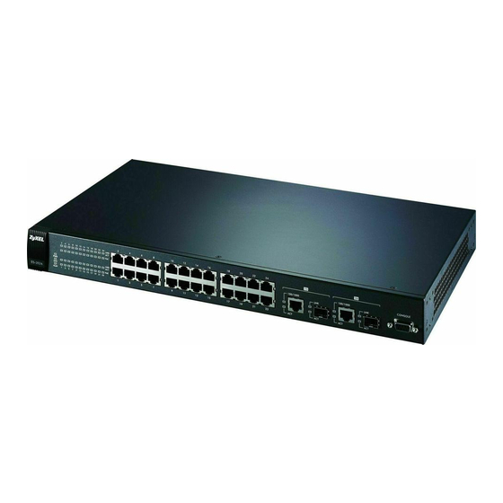
The figure below shows the front panel of the Switch. Figure 8 Front Panel: ES-2024A Console Port Gigabit 10/100 Mbps Ethernet Ethernet/ Mini- Figure 9 Front Panel: ES-2024PWR Console Port Gigabit 10/100 Mbps Ethernet Ethernet/ Mini- ES-2024 Series User’s Guide... -
Page 34: Console Port
1000 Mbps and the duplex mode can be half duplex (at 100 Mbps) or full duplex. An auto-negotiating port can detect and adjust to the optimum Ethernet speed (10/100 Mbps) and duplex mode (full duplex or half duplex) of the connected device. ES-2024 Series User’s Guide... -
Page 35: Mini-Gbic Slots
• Connection speed: 1 Gigabit per second (Gbps) Note: To avoid possible eye injury, do not look into an operating fiber-optic module’s connectors. 3.1.3.1 Transceiver Installation Use the following steps to install a mini GBIC transceiver (SFP module). ES-2024 Series User’s Guide... -
Page 36: Transceiver Removal
Use the following steps to remove a mini GBIC transceiver (SFP module). Open the transceiver’s latch (latch styles vary). Figure 12 Opening the Transceiver’s Latch Example Pull the transceiver out of the slot. Figure 13 Transceiver Removal Example ES-2024 Series User’s Guide... -
Page 37: Rear Panel
The system is rebooting and performing self-diagnostic tests. The system is on and functioning properly. The power is off or the system is not ready/ malfunctioning. There is a hardware failure. The system is functioning normally. Ethernet Ports ES-2024 Series User’s Guide... - Page 38 The link to an Ethernet network is down. Mini-GBIC Ports Green The port has a successful connection. No Ethernet device is connected to this port. Green Blinking The port is sending or receiving data. The port is not sending or receiving data. ES-2024 Series User’s Guide...
-
Page 39: Basic Configuration
Basic Configuration The Web Configurator (41) Initial Setup Example (53) Tutorials (59) System Status and Port Statistics (65) Basic Setting (71) -
Page 41: The Web Configurator
Windows XP SP (Service Pack) 2. • JavaScript (enabled by default). • Java permissions (enabled by default). 4.2 System Login Start your web browser. Type 192.168.1.1 in the Location or Address field. Press [ENTER]. ES-2024 Series User’s Guide... -
Page 42: The Status Screen
General Setup screen. Figure 16 Web Configurator: Login Click OK to view the first web configurator screen. 4.3 The Status Screen The Status screen is the first screen that displays when you access the web configurator. ES-2024 Series User’s Guide... - Page 43 C - Click this link to go to the status page of the Switch. D - Click this link to logout of the web configurator. E - Click this link to display web help pages. The help pages provide descriptions for all of the configuration screens. ES-2024 Series User’s Guide...
- Page 44 Chapter 4 The Web Configurator In the navigation panel, click a main link to reveal a list of submenu links. Table 3 Navigation Panel Sub-links Overview ADVANCED BASIC SETTING IP APPLICATION MANAGEMENT APPLICATION ES-2024 Series User’s Guide...
- Page 45 ARP Table Multicast Setting Configure Clone IGMP Snooping VLAN IGMP Filtering Profile Group Configuration RADIUS Server Setup TACACS+ Server Setup AAA Setup IP Source Guard Static Binding ARP Inspection Status LogStatus Configure Port VLAN Loop Guard ES-2024 Series User’s Guide...
- Page 46 This link takes you to a screen where you can activate MAC address learning and set the maximum number of MAC addresses to learn on a port. Queuing This link takes you to a screen where you can configure queuing with Method associated queue weights. ES-2024 Series User’s Guide...
- Page 47 This link takes you to a screen where you can view the MAC addresses – IP address resolution table. Configure This link takes you to a screen where you can copy attributes of one port Clone to other ports. ES-2024 Series User’s Guide...
-
Page 48: Change Your Password
Note: Use the Save link when you are done with a configuration session. 4.5 Switch Lockout You could block yourself (and all others) from using in-band-management (managing through the data ports) if you do one of the following: Delete the management VLAN (default is VLAN 1). ES-2024 Series User’s Guide... -
Page 49: Resetting The Switch
Switch’s power, you will see the initial screen. When you see the message “Press any key to enter Debug Mode within 3 seconds ...” press any key to enter debug mode. Type atlc after the “Enter Debug Mode” message. ES-2024 Series User’s Guide... -
Page 50: Logging Out Of The Web Configurator
Click Logout in a screen to exit the web configurator. You have to log in with your password again after you log out. This is recommended after you finish a management session for security reasons. Figure 20 Web Configurator: Logout Screen ES-2024 Series User’s Guide... -
Page 51: Help
Chapter 4 The Web Configurator 4.8 Help The web configurator’s online help has descriptions of individual screens and some supplementary information. Click the Help link from a web configurator screen to view an online help description of that screen. ES-2024 Series User’s Guide... - Page 52 Chapter 4 The Web Configurator ES-2024 Series User’s Guide...
-
Page 53: Initial Setup Example
Section 4.2 on page 41 for more information. 5.1.1 Creating a VLAN VLANs confine broadcast frames to the VLAN group in which the port(s) belongs. You can do this with port-based VLAN or tagged static VLAN with fixed port members. ES-2024 Series User’s Guide... - Page 54 10 to be a permanent member of the VLAN only. To ensure that VLAN-unaware devices (such as computers and hubs) can receive frames properly, clear the TX Tagging check box to set the Switch to remove VLAN tags before sending. ES-2024 Series User’s Guide...
-
Page 55: Setting Port Vid
Then click the VLAN Port Setting link. Enter 2 in the PVID field for port 10 and click Apply to set the VLAN port setting and click the Save button to save the settings. ES-2024 Series User’s Guide... -
Page 56: Configuring Switch Management Ip Address
In the VID field, enter the ID of the VLAN group to which you want this management IP address to belong. This is the same as the VLAN ID you configure in the Static VLAN screen. Click Add. ES-2024 Series User’s Guide... - Page 57 Chapter 5 Initial Setup Example ES-2024 Series User’s Guide...
- Page 58 Chapter 5 Initial Setup Example ES-2024 Series User’s Guide...
-
Page 59: Tutorials
IP address (say 172.16.1.18) to DHCP client A based on the system name, VLAN ID and port number in the DHCP request. Client A connects to the Switch’s port 2 in VLAN 102. Figure 24 Tutorial: DHCP Relay Scenario ES-2024 Series User’s Guide... -
Page 60: Creating A Vlan
Name field and enter 102 in the VLAN Group ID field. Select Fixed to configure port 2 to be a permanent member of this VLAN. Clear the TX Tagging check box to set the Switch to remove VLAN tags before sending. ES-2024 Series User’s Guide... - Page 61 Figure 27 Tutorial: Click the VLAN Port Setting Link Enter 102 in the PVID field for port 2 to add a tag to incoming untagged frames received on that port so that the frames are forwarded to the VLAN group that the tag defines. ES-2024 Series User’s Guide...
-
Page 62: Configuring Dhcp Relay
Click IP Application > DHCP and then the Global link to open the DHCP Relay screen. Select the Active check box. Enter the DHCP server’s IP address (192.168.2.3 in this example) in the Remote DHCP Server 1 field. Select the Option 82 and the Information check boxes. ES-2024 Series User’s Guide... -
Page 63: Troubleshooting
You configured the correct VLAN ID, port number and system name for DHCP relay on both the DHCP server and the Switch. You clicked the Save link on the Switch to have your settings take effect. ES-2024 Series User’s Guide... - Page 64 Chapter 6 Tutorials ES-2024 Series User’s Guide...
-
Page 65: System Status And Port Statistics
The home screen of the web configurator displays a port statistical summary with links to each port showing statistical details. 7.2 Port Status Summary To view the port statistics, click Status in any web configurator screen to display the Status screen as shown next. Figure 30 Status ES-2024 Series User’s Guide... - Page 66 This field shows the total amount of time in hours, minutes and seconds the port has been up. Clear Counter Enter a port number and then click Clear Counter to erase the recorded statistical information for that port, or select Any to clear statistics for all ports. ES-2024 Series User’s Guide...
-
Page 67: Status: Port Details
This field displays the speed (either 10M for 10Mbps, 100M for 100Mbps or 1000M for 1000Mbps) and the duplex (F for full duplex or H for half duplex). It also shows the cable type (Copper or Fiber). ES-2024 Series User’s Guide... - Page 68 Error Packet The following fields display detailed information about packets received that were in error. RX CRC This field shows the number of packets received with CRC (Cyclic Redundant Check) error(s). ES-2024 Series User’s Guide...
- Page 69 This field shows the number of packets (including bad packets) received 1518 that were between 1024 and 1518 octets in length. Giant This field shows the number of packets dropped because they were bigger than the maximum frame size. ES-2024 Series User’s Guide...
- Page 70 Chapter 7 System Status and Port Statistics ES-2024 Series User’s Guide...
-
Page 71: Basic Setting
Setup screen allows you to set up and configure global Switch features. The IP Setup screen allows you to configure a Switch IP address in each routing domain, subnet mask(s) and DNS (domain name server) for management purposes. ES-2024 Series User’s Guide... -
Page 72: System Information
This field refers to the Ethernet MAC (Media Access Control) address of the Address Switch. Hardware Monitor (This section is available for the ES-2024 PWR model only) Temperature The Switch has temperature sensors that are capable of detecting and Unit reporting if the temperature rises above the threshold. - Page 73 This field displays the minimum voltage measured at this point. Threshold This field displays the percentage tolerance of the voltage with which the Switch still works. Status Normal indicates that the voltage is within an acceptable operating range at this point; otherwise Error is displayed. ES-2024 Series User’s Guide...
-
Page 74: General Setup
Enter the geographic location of your Switch. You can use up to 32 English keyboard characters; spaces are allowed. Contact Enter the name of the person in charge of this Switch. You can use up to Person's Name 32 English keyboard characters; spaces are allowed. ES-2024 Series User’s Guide... - Page 75 European Union you would select Last, Sunday, March and the last field depends on your time zone. In Germany for instance, you would select 2:00 because Germany's time zone is one hour ahead of GMT or UTC (GMT+1). ES-2024 Series User’s Guide...
-
Page 76: Introduction To Vlans
With VLAN, all broadcasts are confined to a specific broadcast domain. Note: VLAN is unidirectional; it only governs outgoing traffic. Chapter 9 on page 91 for information on port-based and 802.1Q tagged VLANs. ES-2024 Series User’s Guide... -
Page 77: Switch Setup Screen
Join Timer sets the duration of the Join Period timer for GVRP in milliseconds. Each port has a Join Period timer. The allowed Join Time range is between 100 and 65535 milliseconds; the default is 200 milliseconds. See the chapter on VLAN setup for more background information. ES-2024 Series User’s Guide... -
Page 78: Ip Setup
Cancel Click Cancel to begin configuring this screen afresh. 8.6 IP Setup Use the IP Setup screen to configure the default gateway device, the default domain name server and add IP domains. ES-2024 Series User’s Guide... -
Page 79: Ip Interfaces
IP address and vice versa. Enter a domain name server IP address in order to be able to use a domain name instead of an IP address. Default Management IP Address Configure the fields to set the default management IP address. ES-2024 Series User’s Guide... - Page 80 IP Address This field displays the management IP address of the Switch. IP Subnet This field displays the subnet mask for the corresponding IP address. Mask This field displays the VLAN identification number of the network. ES-2024 Series User’s Guide...
-
Page 81: Port Setup
Note: Changes in this row are copied to all the ports as soon as you make them. Active Select this check box to enable a port. The factory default for all ports is enabled. A port must be enabled for data transmission to occur. ES-2024 Series User’s Guide... - Page 82 Switch loses these changes if it is turned off or loses power, so use the Save link on the top navigation panel to save your changes to the non- volatile memory when you are done configuring. Cancel Click Cancel to begin configuring this screen afresh. ES-2024 Series User’s Guide...
-
Page 83: Poe Status
Chapter 8 Basic Setting 8.8 PoE Status Note: The following screens are available for the ES-2024 PWR model only. Some features are only available for the Fast Ethernet ports (1 to 24). Your Switch supports IEEE 802.3af Power over Ethernet (PoE). - Page 84 This field shows which ports can receive power from the Switch. You can set this in Section 8.8.1 on page • Disable - The PD connected to this port cannot get power supply. • Enable - The PD connected to this port can receive power. ES-2024 Series User’s Guide...
-
Page 85: Poe Setup
This field displays the maximum amount of current drawn by the PD from (mA) the Switch on this port. 8.8.1 PoE Setup Use this screen to set the priority levels for the Switch in distributing power to PDs. ES-2024 Series User’s Guide... - Page 86 Port This is the port index number. Select this to provide power to a PD connected to the port. If left unchecked, the PD connected to the port cannot receive power from the Switch. ES-2024 Series User’s Guide...
- Page 87 Switch loses these changes if it is turned off or loses power, so use the Save link on the top navigation panel to save your changes to the non- volatile memory when you are done configuring. Cancel Click Cancel to begin configuring this screen afresh. ES-2024 Series User’s Guide...
- Page 88 Chapter 8 Basic Setting ES-2024 Series User’s Guide...
-
Page 89: Advanced Setup
Advanced Setup VLAN (91) Static MAC Forwarding (105) Static Multicast Forwarding (109) Filtering (113) Spanning Tree Protocol (115) Bandwidth Control (131) Broadcast Storm Control (133) Mirroring (135) Link Aggregation (137) Port Authentication (145) Port Security (149) Queuing Method (153) Multicast (157) AAA (173) IP Source Guard (187) Loop Guard (201) -
Page 91: Vlan
1 Bit 12 bits 9.1.1 Forwarding Tagged and Untagged Frames Each port on the Switch is capable of passing tagged or untagged frames. To forward a frame from an 802.1Q VLAN-aware switch to an 802.1Q VLAN-unaware ES-2024 Series User’s Guide... -
Page 92: Automatic Vlan Registration
Please refer to the following table for common IEEE 802.1Q VLAN terminology. Table 14 IEEE 802.1Q VLAN Terminology VLAN TERM DESCRIPTION PARAMETER VLAN Type Permanent VLAN This is a static VLAN created manually. Dynamic VLAN This is a VLAN configured by a GVRP registration/ deregistration process. ES-2024 Series User’s Guide... -
Page 93: Port Vlan Trunking
VLAN group tags. However, with VLAN Trunking enabled on a port(s) in each intermediary switch you only need to create VLAN groups in the end devices (A and B). C, D and E automatically allow frames with ES-2024 Series User’s Guide... -
Page 94: Select The Vlan Type
• sent to a group whether it has a VLAN tag or not. • blocked from a VLAN group regardless of its VLAN tag. You can also tag all outgoing frames (that were previously untagged) from a port with the specified VID. ES-2024 Series User’s Guide... -
Page 95: Static Vlan Status
GVRP, Static - added as a permanent entry or Other - added in another way such as via Multicast VLAN Registration (MVR). Change Pages Click Previous or Next to show the previous/next screen if all status information cannot be seen in one screen. ES-2024 Series User’s Guide... -
Page 96: Static Vlan Details
Multicast VLAN Registration (MVR). 9.5.3 Configure a Static VLAN Use this screen to configure and view 802.1Q VLAN parameters for the Switch. Section 9.1 on page 91 for more information on static VLAN. To configure a ES-2024 Series User’s Guide... - Page 97 Use this row only if you want to make some settings the same for all ports. Use this row first to set the common settings and then make adjustments on a port-by-port basis. Note: Changes in this row are copied to all the ports as soon as you make them. ES-2024 Series User’s Guide...
-
Page 98: Configure Vlan Port Settings
See Section 9.1 on page 91 for more information on static VLAN. Click the VLAN Port Setting link in the VLAN Status screen. Figure 45 Advanced Application > VLAN > VLAN Port Settings ES-2024 Series User’s Guide... -
Page 99: Port-Based Vlan Setup
Cancel Click Cancel to begin configuring this screen afresh. 9.6 Port-based VLAN Setup Port-based VLANs are VLANs where the packet forwarding decision is based on the destination MAC address and its associated port. ES-2024 Series User’s Guide... - Page 100 Note: In screens (such as IP Setup and Filtering) that require a VID, you must enter 1 as the VID. The port-based VLAN setup screen is shown next. The CPU management port forms a VLAN with all Ethernet ports. ES-2024 Series User’s Guide...
-
Page 101: Configure A Port-Based Vlan
Select Port Based as the VLAN Type in the Switch Setup screen and then click VLAN from the navigation panel to display the next screen. Figure 46 Advanced Application > VLAN: Port Based VLAN Setup (All Connected) ES-2024 Series User’s Guide... - Page 102 Chapter 9 VLAN Figure 47 Advanced Application > VLAN: Port Based VLAN Setup (Port Isolation) ES-2024 Series User’s Guide...
- Page 103 Switch loses these changes if it is turned off or loses power, so use the Save link on the top navigation panel to save your changes to the non- volatile memory when you are done configuring. Cancel Click Cancel to begin configuring this screen afresh. ES-2024 Series User’s Guide...
- Page 104 Chapter 9 VLAN ES-2024 Series User’s Guide...
-
Page 105: Static Mac Forwarding
Static MAC address forwarding together with port security allow only computers in the MAC address table on a port to access the Switch. See Chapter 19 on page for more information on port security. ES-2024 Series User’s Guide... - Page 106 MAC address-forwarding rule. MAC Address This field displays the MAC address that will be forwarded and the VLAN identification number to which the MAC address belongs. This field displays the ID number of the VLAN group. ES-2024 Series User’s Guide...
- Page 107 This field displays the port where the MAC address shown in the next field will be forwarded. Delete Click Delete to remove the selected entry from the summary table. Cancel Click Cancel to clear the Delete check boxes. ES-2024 Series User’s Guide...
- Page 108 Chapter 10 Static MAC Forwarding ES-2024 Series User’s Guide...
-
Page 109: Static Multicast Forwarding
Figure 49 shows such unknown multicast frames flooded to all ports. With static multicast forwarding, you can forward these multicasts to port(s) within a VLAN group. Figure 50 shows frames ES-2024 Series User’s Guide... -
Page 110: Configuring Static Multicast Forwarding
Figure 50 Static Mutlicast Forwarding to A Single Port Figure 51 Static Mutlicast Forwarding to Multiple Ports 11.2 Configuring Static Multicast Forwarding Use this screen to configure rules to forward specific multicast frames, such as streaming or control frames, to specific port(s). ES-2024 Series User’s Guide... - Page 111 Cancel Click Cancel to reset the fields to their last saved values. Clear Click Clear to begin configuring this screen afresh. Index Click an index number to modify a static multicast MAC address rule for port(s). ES-2024 Series User’s Guide...
- Page 112 This field displays the port(s) within a identified VLAN group to which frames containing the specified multicast MAC address will be forwarded. Delete Click Delete to remove the selected entry from the summary table. Cancel Click Cancel to clear the Delete check boxes. ES-2024 Series User’s Guide...
-
Page 113: Filtering
Name Type a descriptive name (up to 32 English keyboard characters) for this rule. This is for identification only. Type a MAC address in valid MAC address format, that is, six hexadecimal character pairs. ES-2024 Series User’s Guide... - Page 114 This field displays the VLAN group identification number. Delete Check the rule(s) that you want to remove in the Delete column and then click the Delete button. Cancel Click Cancel to clear the selected checkbox(es) in the Delete column. ES-2024 Series User’s Guide...
-
Page 115: Spanning Tree Protocol
RSTP and STP flush unwanted learned addresses from the filtering database. In RSTP, the port states are Discarding, Learning, and Forwarding. Note: In this user’s guide, “STP” refers to both STP and RSTP. 13.1.1 STP Terminology The root bridge is the base of the spanning tree. ES-2024 Series User’s Guide... -
Page 116: How Stp Works
Hello BPDU after a predefined interval (Max Age), the bridge assumes that the link to the root bridge is down. This bridge then initiates negotiations with other bridges to reconfigure the network to re-establish a valid network topology. ES-2024 Series User’s Guide... -
Page 117: Stp Port States
13.1.4.1 MSTP Network Example The following figure shows a network example where two VLANs are configured on the two switches. If the switches are using STP or RSTP, the link for VLAN 2 will be ES-2024 Series User’s Guide... -
Page 118: Mst Region
MST region. When BPDUs enter an MST region, external path cost (of paths outside this region) is increased by one. Internal path cost (of paths within this region) is increased by one when BPDUs traverse the region. ES-2024 Series User’s Guide... -
Page 119: Mst Instance
STP/RSTP. The CIST is the default MST instance (MSTID 0). Any VLANs that are not members of an MST instance are members of the CIST. In an MSTP-enabled network, there is only one CIST that runs between MST regions ES-2024 Series User’s Guide... -
Page 120: Spanning Tree Configuration Screen
Switch loses these changes if it is turned off or loses power, so use the Save link on the top navigation panel to save your changes to the non- volatile memory when you are done configuring. Cancel Click Cancel to begin configuring this screen afresh. ES-2024 Series User’s Guide... -
Page 121: Configure Rapid Spanning Tree Protocol
Table 26 Advanced Application > Spanning Tree Protocol > RSTP LABEL DESCRIPTION Status Click Status to display the RSTP Status screen (see Figure 60 on page 123). Active Select this check box to activate RSTP. Clear this check box to disable RSTP. ES-2024 Series User’s Guide... - Page 122 Path cost is the cost of transmitting a frame on to a LAN through that port. It is recommended to assign this value according to the speed of the bridge. The slower the media, the higher the cost. See Table 23 on page 116 for more information. ES-2024 Series User’s Guide...
-
Page 123: Rapid Spanning Tree Protocol Status
The root bridge determines Hello Time, Max Age and Forwarding Delay. Max Age This is the maximum time (in seconds) a switch can wait without (second) receiving a configuration message before attempting to reconfigure. ES-2024 Series User’s Guide... - Page 124 Switch must communicate with the root of the Spanning Tree. Topology This is the number of times the spanning tree has been reconfigured. Changed Times Time Since Last This is the time since the spanning tree was last reconfigured. Change ES-2024 Series User’s Guide...
-
Page 125: Configure Multiple Spanning Tree Protocol
13.5 Configure Multiple Spanning Tree Protocol To configure MSTP, click MSTP in the Advanced Application > Spanning Tree Protocol screen. See Section 13.1.4 on page 117 for more information on MSTP. Figure 61 Advanced Application > Spanning Tree Protocol > MSTP ES-2024 Series User’s Guide... - Page 126 Enter priority values between 0 and 61440 in increments of 4096 (thus valid values are 0, 4096, 8192, 12288, 16384, 20480, 24576, 28672, 32768, 36864, 40960, 45056, 49152, 53248, 57344 and 61440). ES-2024 Series User’s Guide...
- Page 127 This field display the ports configured to participate in the MST instance. Delete Check the rule(s) that you want to remove in the Delete column and then click the Delete button. Cancel Click Cancel to begin configuring this screen afresh. ES-2024 Series User’s Guide...
-
Page 128: Multiple Spanning Tree Protocol Status
Click MSTP to edit MSTP settings on the Switch. This section describes the Common Spanning Tree settings. Bridge Root refers to the base of the spanning tree (the root bridge). Our Bridge is this Switch. This Switch may also be the root bridge. ES-2024 Series User’s Guide... - Page 129 This is the path cost from the root port in this MST instance to the regional root switch. Port ID This is the priority and number of the port on the Switch through which this Switch must communicate with the root of the MST instance. ES-2024 Series User’s Guide...
- Page 130 Chapter 13 Spanning Tree Protocol ES-2024 Series User’s Guide...
-
Page 131: Bandwidth Control
Bandwidth control means defining a maximum allowable bandwidth for incoming and/or out-going traffic flows on a port. Click Advanced Application > Bandwidth Control in the navigation panel to bring up the screen as shown next. Figure 63 Advanced Application > Bandwidth Control ES-2024 Series User’s Guide... - Page 132 Switch loses these changes if it is turned off or loses power, so use the Save link on the top navigation panel to save your changes to the non- volatile memory when you are done configuring. Cancel Click Cancel to begin configuring this screen afresh. ES-2024 Series User’s Guide...
-
Page 133: Broadcast Storm Control
DLF packets in your network. You can specify limits for each packet type on each port. Click Advanced Application > Broadcast Storm Control in the navigation panel to display the screen as shown next. Figure 64 Advanced Application > Broadcast Storm Control ES-2024 Series User’s Guide... - Page 134 Switch loses these changes if it is turned off or loses power, so use the Save link on the top navigation panel to save your changes to the non- volatile memory when you are done configuring. Cancel Click Cancel to begin configuring this screen afresh. ES-2024 Series User’s Guide...
-
Page 135: Mirroring
Click Advanced Application > Mirroring in the navigation panel to display the Mirroring screen. Use this screen to select a monitor port and specify the traffic flow to be copied to the monitor port. Figure 65 Advanced Application > Mirroring ES-2024 Series User’s Guide... - Page 136 Switch loses these changes if it is turned off or loses power, so use the Save link on the top navigation panel to save your changes to the non-volatile memory when you are done configuring. Cancel Click Cancel to begin configuring this screen afresh. ES-2024 Series User’s Guide...
-
Page 137: Link Aggregation
The Switch adheres to the IEEE 802.3ad standard for static and dynamic (LACP) port trunking. The Switch supports the link aggregation IEEE802.3ad standard. This standard describes the Link Aggregate Control Protocol (LACP), which is a protocol that dynamically creates and manages trunk groups. ES-2024 Series User’s Guide... -
Page 138: Link Aggregation Id
Table 34 Link Aggregation ID: Peer Switch SYSTEM PORT PORT PRIORITY ADDRESS PRIORITY NUMBER 0000 00-00-00-00- 0000 0000 Port Priority and Port Number are 0 as it is the aggregator ID for the trunk group, not the individual port. ES-2024 Series User’s Guide... -
Page 139: Link Aggregation Status
This field displays how these ports were added to the trunk group. It displays: • Static - if the ports are configured as static members of a trunk group. • LACP - if the ports are configured to join a trunk group via LACP. ES-2024 Series User’s Guide... -
Page 140: Link Aggregation Setting
Switch loses these changes if it is turned off or loses power, so use the Save link on the top navigation panel to save your changes to the non- volatile memory when you are done configuring. Cancel Click Cancel to begin configuring this screen afresh. ES-2024 Series User’s Guide... -
Page 141: Link Aggregation Control Protocol
Table 37 Advanced Application > Link Aggregation > Link Aggregation Setting > LACP LABEL DESCRIPTION Link Note: Do not configure this screen unless you want to enable Aggregation dynamic link aggregation. Control Protocol Active Select this checkbox to enable Link Aggregation Control Protocol (LACP). ES-2024 Series User’s Guide... -
Page 142: Static Trunking Example
Save link on the top navigation panel to save your changes to the non- volatile memory when you are done configuring. Cancel Click Cancel to begin configuring this screen afresh. 17.6 Static Trunking Example This example shows you how to create a static port trunk group for ports 2-5. ES-2024 Series User’s Guide... - Page 143 Click Apply when you are done. Figure 70 Trunking Example - Configuration Screen Your trunk group 1 (T1) configuration is now complete; you do not need to go to any additional screens. ES-2024 Series User’s Guide...
- Page 144 Chapter 17 Link Aggregation ES-2024 Series User’s Guide...
-
Page 145: Port Authentication
At the time of writing, IEEE 802.1x is not supported by all operating systems. See your operating system documentation. If your operating system does not support 802.1x, then you may need to install 802.1x client software. ES-2024 Series User’s Guide... -
Page 146: Port Authentication Configuration
(both on the Switch and the port(s)) then configure the RADIUS server settings in the AAA > Radius Server Setup screen. Click Advanced Application > Port Authentication in the navigation panel to display the screen as shown. Figure 72 Advanced Application > Port Authentication ES-2024 Series User’s Guide... -
Page 147: Activate Ieee 802.1X Security
Specify if a subscriber has to periodically re-enter his or her username and password to stay connected to the port. Reauthenticati Specify how often a client has to re-enter his or her username and on Timer password to stay connected to the port. ES-2024 Series User’s Guide... - Page 148 Switch loses these changes if it is turned off or loses power, so use the Save link on the top navigation panel to save your changes to the non- volatile memory when you are done configuring. Cancel Click Cancel to begin configuring this screen afresh. ES-2024 Series User’s Guide...
-
Page 149: Port Security
• Drop all packets from unknown MAC addresses and learn a limited number of MAC addresses. Note: The Switch supports five possible configurations for port security. See Section 19.3 on page 151 for supported configurations and an example. ES-2024 Series User’s Guide... -
Page 150: Port Security Setup
Use this row only if you want to make some settings the same for all ports. Use this row first to set the common settings and then make adjustments on a port-by-port basis. Note: Changes in this row are copied to all the ports as soon as you make them. ES-2024 Series User’s Guide... -
Page 151: Port Security Example
• Port 2 - Forward all packets and learn all MAC addresses. • Port 3 - Drop all packets from unknown MAC addresses and do not learn MAC addresses. • Port 4 - Drop all packets from unknown MAC addresses and do not learn MAC addresses. ES-2024 Series User’s Guide... - Page 152 Drop all packets from unknown limits) MAC addresses, do not learn MAC addresses. Drop all packets from unknown MAC addresses, do not learn MAC addresses. Drop packets from unknown MAC addresses, learn up to 100 MAC addresses. ES-2024 Series User’s Guide...
-
Page 153: Queuing Method
20.1.2 Weighted Round Robin Scheduling (WRR) Round Robin Scheduling services queues on a rotating basis and is activated only when a port has more traffic than it can handle. A queue is a given an amount of ES-2024 Series User’s Guide... -
Page 154: Configuring Queuing
This queuing mechanism is highly efficient in that it divides any available bandwidth across the different traffic queues and returns to queues that have not yet emptied. 20.2 Configuring Queuing Click Advanced Application > Queuing Method in the navigation panel. Figure 76 Advanced Application > Queuing Method ES-2024 Series User’s Guide... - Page 155 Switch loses these changes if it is turned off or loses power, so use the Save link on the top navigation panel to save your changes to the non-volatile memory when you are done configuring. Cancel Click Cancel to begin configuring this screen afresh. ES-2024 Series User’s Guide...
- Page 156 Chapter 20 Queuing Method ES-2024 Series User’s Guide...
-
Page 157: Multicast
(such as content information distribution) based on service plans and types of subscription. You can set the Switch to filter the multicast group join reports on a per-port basis by configuring an IGMP filtering profile and associating the profile to a port. ES-2024 Series User’s Guide... -
Page 158: Igmp Snooping
Figure 77 Advanced Application > Multicast The following table describes the labels in this screen. Table 43 Multicast Status LABEL DESCRIPTION Index This is the index number of the entry. This field displays the multicast VLAN ID. ES-2024 Series User’s Guide... -
Page 159: Multicast Setting
Table 44 Advanced Application > Multicast > Multicast Setting LABEL DESCRIPTION IGMP Snooping Use these settings to configure IGMP Snooping. Active Select Active to enable IGMP Snooping to forward group multicast traffic only to ports that are members of that group. ES-2024 Series User’s Guide... - Page 160 Select the name of the IGMP filtering profile to use for this port. Profile Otherwise, select Default to prohibit the port from joining any multicast group. You can create IGMP filtering profiles in the Multicast > Multicast Setting > IGMP Filtering Profile screen. ES-2024 Series User’s Guide...
-
Page 161: Igmp Snooping Vlan
Multicast Setting link and then the IGMP Snooping VLAN link to display the screen as shown. See Section 21.1.4 on page 158 for more information on IGMP Snooping VLAN. Figure 79 Advanced Application > Multicast > Multicast Setting > IGMP Snooping VLAN ES-2024 Series User’s Guide... - Page 162 This field displays the ID number of the VLAN group. Delete Check the rule(s) that you want to remove in the Delete column, then click the Delete button. Cancel Click Cancel to clear the Delete check boxes. ES-2024 Series User’s Guide...
-
Page 163: Igmp Filtering Profile
Switch loses these changes if it is turned off or loses power, so use the Save link on the top navigation panel to save your changes to the non- volatile memory when you are done configuring. ES-2024 Series User’s Guide... -
Page 164: Mvr Overview
The following figure shows a network example. The subscriber VLAN (1, 2 and 3) information is hidden from the streaming media server, S. In addition, the multicast VLAN information is only visible to the Switch and S. Figure 81 MVR Network Example ES-2024 Series User’s Guide... -
Page 165: Types Of Mvr Ports
VLAN 1 on the receiver port (in this case, an uplink port on the Switch). If there is another subscriber device connected to this port in the same subscriber VLAN, the receiving port will still be on the list of forwarding destination ES-2024 Series User’s Guide... -
Page 166: General Mvr Configuration
VLAN. Click Advanced Applications > Multicast > Multicast Setting > MVR link to display the screen as shown next. Note: You can create up to three multicast VLANs and up to 256 multicast rules on the Switch. ES-2024 Series User’s Guide... - Page 167 Select Dynamic to send IGMP reports to all MVR source ports in the multicast VLAN. Select Compatible to set the Switch not to send IGMP reports. Port This field displays the port number on the Switch. ES-2024 Series User’s Guide...
-
Page 168: Mvr Group Configuration
All source ports and receiver ports belonging to a multicast group can receive multicast data sent to this multicast group. Configure MVR IP multicast group address(es) in the Group Configuration screen. Click Group Configuration in the MVR screen. ES-2024 Series User’s Guide... - Page 169 Name This field displays the descriptive name for this setting. Start This field displays the starting IP address of the multicast group. Address End Address This field displays the ending IP address of the multicast group. ES-2024 Series User’s Guide...
-
Page 170: Mvr Configuration Example
VID 200 to receive multicast traffic (the News and Movie channels) from the remote streaming media server, S. Computers A, B and C in VLAN 1 are able to receive the traffic. Figure 85 MVR Configuration Example ES-2024 Series User’s Guide... - Page 171 Figure 86 MVR Configuration Example To set the Switch to forward the multicast group traffic to the subscribers, configure multicast group settings in the Group Configuration screen. The ES-2024 Series User’s Guide...
- Page 172 Chapter 21 Multicast following figure shows an example where two multicast groups (News and Movie) are configured for the multicast VLAN 200. Figure 87 MVR Group Configuration Example Figure 88 MVR Group Configuration Example ES-2024 Series User’s Guide...
-
Page 173: Aaa
The external servers that perform authentication, authorization and accounting functions are known as AAA servers. The Switch supports RADIUS (Remote Authentication Dial-In User Service, see Section 22.1.2 on page 174) and TACACS+ (Terminal Access Controller Access-Control System Plus, see Section ES-2024 Series User’s Guide... -
Page 174: Local User Accounts
(the Switch) and the TACACS server is encrypted. 22.2 AAA Screens To enable authentication, accounting or both on the Switch. First, configure your authentication server settings (RADIUS, TACACS+ or both) and then set up the authentication priority and accounting settings. ES-2024 Series User’s Guide... -
Page 175: Radius Server Setup
Section 22.1.2 on page 174 for more information on RADIUS servers. Click on the RADIUS Server Setup link in the AAA screen to view the screen as shown. Figure 91 Advanced Application > AAA > RADIUS Server Setup ES-2024 Series User’s Guide... - Page 176 RADIUS accounting server. Index This is a read-only number representing a RADIUS accounting server entry. IP Address Enter the IP address of an external RADIUS accounting server in dotted decimal notation. ES-2024 Series User’s Guide...
-
Page 177: Tacacs+ Server Setup
Section 22.1.2 on page 174 for more information on TACACS+ servers. Click on the TACACS+ Server Setup link in the AAA screen to view the screen as shown. Figure 92 Advanced Application > AAA > TACACS+ Server Setup ES-2024 Series User’s Guide... - Page 178 Specify the amount of time in seconds that the Switch waits for an accounting request response from the TACACS+ server. Index This is a read-only number representing a TACACS+ accounting server entry. IP Address Enter the IP address of an external TACACS+ accounting server in dotted decimal notation. ES-2024 Series User’s Guide...
-
Page 179: Aaa Setup
Use this screen to configure authentication and accounting settings on the Switch. Click on the AAA Setup link in the AAA screen to view the screen as shown. Figure 93 Advanced Application > AAA > AAA Setup ES-2024 Series User’s Guide... - Page 180 Exec: Allow an administrator which logs in the Switch through Telnet or SSH to have different access privilege level assigned via the external server. • Dot1x: Allow an IEEE 802.1x client to have different bandwidth limit or VLAN ID assigned via the external server. ES-2024 Series User’s Guide...
- Page 181 Switch loses these changes if it is turned off or loses power, so use the Save link on the top navigation panel to save your changes to the non- volatile memory when you are done configuring. Cancel Click Cancel to begin configuring this screen afresh. ES-2024 Series User’s Guide...
-
Page 182: Vendor Specific Attribute
VSAs for users authenticating via the RADIUS server. The following table describes the VSAs supported on the Switch. Table 53 Supported VSAs FUNCTION ATTRIBUTE Ingress Bandwidth Vendor-Id = 890 Assignment Vendor-Type = 1 Vendor-data = ingress rate (Kbps in decimal format) ES-2024 Series User’s Guide... -
Page 183: Supported Radius Attributes
Remote Authentication Dial-In User Service (RADIUS) attributes are data used to define specific authentication, and accounting elements in a user profile, which is stored on the RADIUS server. This appendix lists the RADIUS attributes supported by the Switch. ES-2024 Series User’s Guide... -
Page 184: Attributes Used For Authentication
22.3.1.2 Attributes Used to Login Users User-Name User-Password NAS-Identifier NAS-IP-Address 22.3.1.3 Attributes Used by the IEEE 802.1x Authentication User-Name NAS-Identifier NAS-IP-Address NAS-Port NAS-Port-Type - This value is set to Ethernet(15) on the Switch. Calling-Station-Id Frame-MTU EAP-Message State Message-Authenticator ES-2024 Series User’s Guide... -
Page 185: Attributes Used For Accounting
Table 55 RADIUS Attributes - Exec Events via Console ATTRIBUTE START INTERIM-UPDATE STOP User-Name NAS-Identifier NAS-IP-Address Service-Type Acct-Status-Type Acct-Delay-Time Acct-Session-Id Acct-Authentic Acct-Session-Time Acct-Terminate-Cause Table 56 RADIUS Attributes - Exec Events via Telnet/SSH ATTRIBUTE START INTERIM-UPDATE STOP User-Name NAS-Identifier NAS-IP-Address Service-Type Calling-Station-Id Acct-Status-Type Acct-Delay-Time ES-2024 Series User’s Guide... - Page 186 Table 57 RADIUS Attributes - Exec Events via Console ATTRIBUTE START INTERIM-UPDATE STOP User-Name NAS-IP-Address NAS-Port Class Called-Station-Id Calling-Station-Id NAS-Identifier NAS-Port-Type Acct-Status-Type Acct-Delay-Time Acct-Session-Id Acct-Authentic Acct-Input-Octets Acct-Output-Octets Acct-Session-Time Acct-Input-Packets Acct-Output-Packets Acct-Terminate-Cause Acct-Input-Gigawords Acct-Output- Gigawords ES-2024 Series User’s Guide...
-
Page 187: Ip Source Guard
The Switch builds from information provided manually by administrators (static bindings). IP source guard consists of the following features: • Static bindings. Use this to create static bindings in the binding table. • ARP inspection. Use this to filter unauthorized ARP packets on the network. ES-2024 Series User’s Guide... -
Page 188: Arp Inspection Overview
• They do not use the same space in memory that regular MAC address filters use. • They appear only in the ARP Inspection screens and commands, not in the MAC Address Filter screens and commands. ES-2024 Series User’s Guide... -
Page 189: Ip Source Guard
ARP inspection to distinguish between authorized and unauthorized packets in the network. The Switch learns the bindings from information provided manually by administrators (static bindings). To open this screen, click Advanced Application > IP Source Guard. Figure 95 IP Source Guard ES-2024 Series User’s Guide... -
Page 190: Ip Source Guard Static Binding
MAC address and VLAN ID. Each MAC address and VLAN ID can only be in one static binding. If you try to create a static binding with the same MAC address and VLAN ID as an existing static binding, the new static ES-2024 Series User’s Guide... - Page 191 This field displays how long the binding is valid. Type This field displays how the Switch learned the binding. static: This binding was learned from information provided manually by an administrator. VLAN This field displays the source VLAN ID in the binding. ES-2024 Series User’s Guide...
-
Page 192: Arp Inspection Status
This field displays the source port of the discarded ARP packet. Expiry (sec) This field displays how long (in seconds) the MAC address filter remains in the Switch. You can also delete the record manually (Delete). ES-2024 Series User’s Guide... -
Page 193: Arp Inspection Log Status
Index This field displays a sequential number for each log message. Port This field displays the source port of the ARP packet. ES-2024 Series User’s Guide... -
Page 194: Arp Inspection Configure
This field displays when the log message was generated. 23.5 ARP Inspection Configure Use this screen to enable ARP inspection on the Switch. You can also configure the length of time the Switch stores records of discarded ARP packets and global ES-2024 Series User’s Guide... - Page 195 Enter how long (1-2147483647 seconds) the MAC address filter remains in the Switch after the Switch identifies an unauthorized ARP packet. The Switch automatically deletes the MAC address filter afterwards. Enter 0 if you want the MAC address filter to be permanent. Log Profile ES-2024 Series User’s Guide...
- Page 196 Save link on the top navigation panel to save your changes to the non-volatile memory when you are done configuring. Cancel Click this to reset the values in this screen to their last-saved values. ES-2024 Series User’s Guide...
-
Page 197: Arp Inspection Port Configure
Save link on the top navigation panel to save your changes to the non-volatile memory when you are done configuring. Cancel Click this to reset the values in this screen to their last-saved values. ES-2024 Series User’s Guide... -
Page 198: Arp Inspection Vlan Configure
This field displays the VLAN ID of each VLAN in the range specified above. If you configure the * VLAN, the settings are applied to all VLANs. Enabled Select Yes to enable ARP inspection on the VLAN. Select No to disable ARP inspection on the VLAN. ES-2024 Series User’s Guide... - Page 199 Save link on the top navigation panel to save your changes to the non-volatile memory when you are done configuring. Cancel Click this to reset the values in this screen to their last-saved values. ES-2024 Series User’s Guide...
- Page 200 Chapter 23 IP Source Guard ES-2024 Series User’s Guide...
-
Page 201: Loop Guard
If a switch (not in loop state) connects to a switch in loop state, then it will be affected by the switch in loop state in the following way: ES-2024 Series User’s Guide... - Page 202 The following figure illustrates three switches forming a loop. A sample path of the loop guard probe packet is also shown. In this example, the probe packet is sent from port N and returns on another port. As long as loop guard is enabled on ES-2024 Series User’s Guide...
-
Page 203: Loop Guard Setup
Click Advanced Application > Loop Guard in the navigation panel to display the screen as shown. Note: The loop guard feature can not be enabled on the ports that have Spanning Tree Protocol (RSTP or MSTP) enabled. Figure 106 Advanced Application > Loop Guard ES-2024 Series User’s Guide... - Page 204 Switch loses these changes if it is turned off or loses power, so use the Save link on the top navigation panel to save your changes to the non- volatile memory when you are done configuring. Cancel Click Cancel to begin configuring this screen afresh. ES-2024 Series User’s Guide...
-
Page 205: Ip Application
IP Application Static Route (207) Differentiated Services (211) DHCP (215) -
Page 207: Static Route
R1 which routes it back to the manager’s computer. The Switch needs a static route to tell it to use router R2 to send traffic to an SNMP trap server on network N2. Figure 107 Static Routing Overview ES-2024 Series User’s Guide... -
Page 208: Configuring Static Routing
Save link on the top navigation panel to save your changes to the non- volatile memory when you are done configuring. Cancel Click Cancel to begin configuring this screen afresh. Clear Click Clear to set the above fields back to the factory defaults. ES-2024 Series User’s Guide... - Page 209 Switch that will forward the packet to the destination. Metric This field displays the cost of transmission for routing purposes. Delete Click Delete to remove the selected entry from the summary table. Cancel Click Cancel to clear the Delete check boxes. ES-2024 Series User’s Guide...
- Page 210 Chapter 25 Static Route ES-2024 Series User’s Guide...
-
Page 211: Differentiated Services
ToS-enabled network device will not conflict with the DSCP mapping. The DSCP value determines the PHB (Per-Hop Behavior), that each packet gets as it is forwarded across the DiffServ network. Based on the marking rule different ES-2024 Series User’s Guide... -
Page 212: Diffserv Network Example
Platinum traffic flow as they move across the DiffServ network. Figure 110 DiffServ Network 26.2 Activating DiffServ Activate DiffServ to apply marking rules or IEEE 802.1p priority mapping on the selected port(s). ES-2024 Series User’s Guide... - Page 213 Switch loses these changes if it is turned off or loses power, so use the Save link on the top navigation panel to save your changes to the non- volatile memory when you are done configuring. Cancel Click Cancel to begin configuring this screen afresh. ES-2024 Series User’s Guide...
-
Page 214: Dscp-To-Ieee 802.1P Priority Settings
Save link on the top navigation panel to save your changes to the non-volatile memory when you are done configuring. Cancel Click Cancel to begin configuring this screen afresh. ES-2024 Series User’s Guide... -
Page 215: Dhcp
• Global - The Switch forwards all DHCP requests to the same DHCP server. • VLAN - The Switch is configured on a VLAN by VLAN basis. The Switch can be configured to relay DHCP requests to different DHCP servers for clients in different VLAN. ES-2024 Series User’s Guide... -
Page 216: Dhcp Status
DHCP server by adding Relay Agent Information. This helps provide authentication about the source of the requests. The DHCP server can then provide an IP address based on this information. Please refer to RFC 3046 for more details. ES-2024 Series User’s Guide... -
Page 217: Configuring Dhcp Global Relay
Configure global DHCP relay in the DHCP Relay screen. Click IP Application > DHCP in the navigation panel and click the Global link to display the screen as shown. Figure 114 IP Application > DHCP > Global ES-2024 Series User’s Guide... -
Page 218: Global Dhcp Relay Configuration Example
The follow figure shows a network example where the Switch is used to relay DHCP requests for the VLAN1 and VLAN2 domains. There is only one DHCP server that services the DHCP clients in both domains. Figure 115 Global DHCP Relay Network Example VLAN1 ES-2024 Series User’s Guide... -
Page 219: Configuring Dhcp Vlan Settings
Note: You must set up a management IP address for each VLAN that you want to configure DHCP settings for on the Switch. See Section 8.6 on page 78 information on how to do this. Figure 117 IP Application > DHCP > VLAN ES-2024 Series User’s Guide... -
Page 220: Example: Dhcp Relay For Two Vlans
The following example displays two VLANs (VIDs 1 and 2) for a campus network. Two DHCP servers are installed to serve each VLAN. The system is set up to forward DHCP requests from the dormitory rooms (VLAN 1) to the DHCP server ES-2024 Series User’s Guide... - Page 221 2) are sent to the other DHCP server with an IP address of 172.23.10.100. Figure 118 DHCP Relay for Two VLANs For the example network, configure the VLAN Setting screen as shown. Figure 119 DHCP Relay for Two VLANs Configuration Example ES-2024 Series User’s Guide...
- Page 222 Chapter 27 DHCP ES-2024 Series User’s Guide...
-
Page 223: Management
Management Maintenance (225) Access Control (233) Diagnostic (255) Syslog (257) Cluster Management (261) MAC Table (269) ARP Table (273) Configure Clone (275) -
Page 225: Maintenance
Firmware Click Click Here to go to the Firmware Upgrade screen. Upgrade Restore Click Click Here to go to the Restore Configuration screen. Configurati Backup Click Click Here to go to the Backup Configuration screen. Configurati ES-2024 Series User’s Guide... -
Page 226: Load Factory Default
Click Config 1 to save the current configuration settings permanently to Configuration 1 on the Switch. Alternatively, click Save on the top right-hand corner in any screen to save the configuration changes to the current configuration. ES-2024 Series User’s Guide... -
Page 227: Reboot System
Be sure to upload the correct model firmware as uploading the wrong model firmware may damage your device. From the Maintenance screen, display the Firmware Upgrade screen as shown next. Figure 123 Management > Maintenance > Firmware Upgrade ES-2024 Series User’s Guide... -
Page 228: Restore A Configuration File
28.7 Backup a Configuration File Backing up your Switch configurations allows you to create various “snap shots” of your device from which you may restore at a later date. ES-2024 Series User’s Guide... -
Page 229: Ftp Command Line
Switch setup, IP Setup, and so on. Once you have customized the Switch’s settings, they can be saved back to your computer under a filename of your choosing. ES-2024 Series User’s Guide... -
Page 230: Ftp Command Line Procedure
Enter open, followed by a space and the IP address of your Switch. Press [ENTER] when prompted for a username. Enter your password as requested (the default is “1234”). Enter bin to set transfer mode to binary. ES-2024 Series User’s Guide... -
Page 231: Gui-Based Ftp Clients
• FTP service is disabled in the Service Access Control screen. • The IP address(es) in the Remote Management screen does not match the client IP address. If it does not match, the Switch will disconnect the Telnet session immediately. ES-2024 Series User’s Guide... - Page 232 Chapter 28 Maintenance ES-2024 Series User’s Guide...
-
Page 233: Access Control
See the CLI Reference Guide for more information on disabling multi-login. 29.2 The Access Control Main Screen Click Management > Access Control in the navigation panel to display the main screen as shown. Figure 126 Management > Access Control ES-2024 Series User’s Guide... -
Page 234: About Snmp
A Management Information Base (MIB) is a collection of managed objects. SNMP allows a manager and agents to communicate for the purpose of accessing these objects. ES-2024 Series User’s Guide... -
Page 235: Snmp V3 And Security
• RFC 1155 SMI • RFC 2674 SNMPv2, SNMPv2c • RFC 1757 RMON • SNMPv2, SNMPv2c or later version, compliant with RFC 2011 SNMPv2 MIB for IP, RFC 2012 SNMPv2 MIB for TCP, RFC 2013 SNMPv2 MIB for UDP ES-2024 Series User’s Guide... -
Page 236: Snmp Traps
1.3.6.1.4.1.890.1.5.8.16.2 This trap is sent when the 7.2.1 Switch resets by an administrator through a 1.3.6.1.4.1.890.1.5.8.27.2 management interface. 7.2.1 RebootEvent 1.3.6.1.4.1.890.1.5.1.1.2 This trap is sent when the Switch reboots by an administrator through a management interface. ES-2024 Series User’s Guide... - Page 237 This trap is sent when an ntOn .2.1 Ethernet interface fails to auto-negotiate with the 1.3.6.1.4.1.890.1.5.8.27.27 peer Ethernet interface. .2.1 AutonegotiationFailedEve 1.3.6.1.4.1.890.1.5.8.16.27 This trap is sent when an ntClear .2.2 Ethernet interface auto- negotiates with the peer 1.3.6.1.4.1.890.1.5.8.27.27 Ethernet interface. .2.2 ES-2024 Series User’s Guide...
- Page 238 1.3.6.1.4.1.890.1.5.8.16.27 This trap is sent when there is entOn .2.1 no response message from the RADIUS server. 1.3.6.1.4.1.890.1.5.8.27.27 .2.1 RADIUSNotReachableEv 1.3.6.1.4.1.890.1.5.8.16.27 This trap is sent when the entClear .2.2 RADIUS server can be reached. 1.3.6.1.4.1.890.1.5.8.27.27 .2.2 ES-2024 Series User’s Guide...
- Page 239 This trap is sent when the MSTP 07.70.1 root switch changes. 1.3.6.1.4.1.890.1.5.8.27.1 07.70.1 STPTopologyChange 1.3.6.1.2.1.17.0.2 This trap is sent when the STP topology changes. MSTPTopologyChange 1.3.6.1.4.1.890.1.5.8.16.1 This trap is sent when the MSTP 07.70.2 root switch changes. 1.3.6.1.4.1.890.1.5.8.27.1 07.70.2 ES-2024 Series User’s Guide...
-
Page 240: Configuring Snmp
RMON "falling" threshold. 29.3.4 Configuring SNMP From the Access Control screen, display the SNMP screen. You can click Access Control to go back to the Access Control screen. Figure 128 Management > Access Control > SNMP ES-2024 Series User’s Guide... - Page 241 SNMP v3 manager. Index This is a read-only number identifying a login account on the Switch. Username This field displays the username of a login account on the Switch. ES-2024 Series User’s Guide...
- Page 242 Switch loses these changes if it is turned off or loses power, so use the Save link on the top navigation panel to save your changes to the non- volatile memory when you are done configuring. Cancel Click Cancel to begin configuring this screen afresh. ES-2024 Series User’s Guide...
-
Page 243: Configuring Snmp Trap Group
Switch loses these changes if it is turned off or loses power, so use the Save link on the top navigation panel to save your changes to the non- volatile memory when you are done configuring. Cancel Click Cancel to begin configuring this screen afresh. ES-2024 Series User’s Guide... -
Page 244: Setting Up Login Accounts
This is the default administrator account with the “admin” user name. You cannot change the default administrator user name. Only the administrator has read/write access. Old Password Type the existing system password (1234 is the default password when shipped). New Password Enter your new system password. ES-2024 Series User’s Guide... -
Page 245: Ssh Overview
Unlike Telnet or FTP, which transmit data in clear text, SSH (Secure Shell) is a secure communication protocol that combines authentication and data encryption to provide secure encrypted communication between two hosts over an unsecured network. Figure 131 SSH Communication Example ES-2024 Series User’s Guide... -
Page 246: How Ssh Works
Encryption Method Once the identification is verified, both the client and server must agree on the type of encryption method to use. ES-2024 Series User’s Guide... -
Page 247: Ssh Implementation On The Switch
If the user decides to trust the certificate, the certificate is used in building the HTTPS connection. Please refer to the following figure. HTTPS connection requests from an SSL-aware web browser go to port 443 (by default) on the Switch’s WS (web server). ES-2024 Series User’s Guide... -
Page 248: Https Example
When you attempt to access the Switch HTTPS server, a Windows dialog box pops up asking if you trust the server certificate. Click View Certificate if you want to verify that the certificate is from the Switch. ES-2024 Series User’s Guide... -
Page 249: Netscape Navigator Warning Messages
Unknown Authority screen pops up asking if you trust the server certificate. Click Examine Certificate if you want to verify that the certificate is from the Switch. If Accept this certificate temporarily for this session is selected, then click OK to continue in Netscape. ES-2024 Series User’s Guide... - Page 250 Chapter 29 Access Control Select Accept this certificate permanently to import the Switch’s certificate into the SSL client. Figure 135 Security Certificate 1 (Netscape) Figure 136 Security Certificate 2 (Netscape) ES-2024 Series User’s Guide...
-
Page 251: The Main Screen
Figure 137 Example: Lock Denoting a Secure Connection 29.9 Service Port Access Control Service Access Control allows you to decide what services you may use to access the Switch. You may also change the default service port and configure “trusted ES-2024 Series User’s Guide... -
Page 252: Remote Management
Cancel Click Cancel to begin configuring this screen afresh. 29.10 Remote Management From the Access Control screen, display the Remote Management screen as shown next. ES-2024 Series User’s Guide... - Page 253 Switch loses these changes if it is turned off or loses power, so use the Save link on the top navigation panel to save your changes to the non- volatile memory when you are done configuring. Cancel Click Cancel to begin configuring this screen afresh. ES-2024 Series User’s Guide...
- Page 254 Chapter 29 Access Control ES-2024 Series User’s Guide...
-
Page 255: Diagnostic
This chapter explains the Diagnostic screen. 30.1 Diagnostic Click Management > Diagnostic in the navigation panel to open this screen. Use this screen to check system logs, ping IP addresses or perform port tests. Figure 140 Management > Diagnostic ES-2024 Series User’s Guide... - Page 256 Type the IP address of a device that you want to ping in order to test a connection. Click Ping to have the Switch ping the IP address (in the field to the left). Ethernet Port Enter a port number and click Port Test to perform an internal Test loopback test. ES-2024 Series User’s Guide...
-
Page 257: Syslog
Error: There is an error condition on the system. Warning: There is a warning condition on the system. Notice: There is a normal but significant condition on the system. Informational: The syslog contains an informational message. Debug: The message is intended for debug-level purposes. ES-2024 Series User’s Guide... -
Page 258: Syslog Setup
The Switch loses these changes if it is turned off or loses power, so use the Save link on the top navigation panel to save your changes to the non-volatile memory when you are done configuring. Cancel Click Cancel to begin configuring this screen afresh. ES-2024 Series User’s Guide... -
Page 259: Syslog Server Setup
This field displays the severity level of the logs that the device is to send to this syslog server. Delete Select an entry’s Delete check box and click Delete to remove the entry. Cancel Click Cancel to begin configuring this screen afresh. ES-2024 Series User’s Guide... - Page 260 Chapter 31 Syslog ES-2024 Series User’s Guide...
-
Page 261: Cluster Management
Maximum number of cluster members Cluster Member Models Must be compatible with ZyXEL cluster management implementation. Cluster Manager The switch through which you manage the cluster member switches. Cluster Members The switches being managed by the cluster manager switch. ES-2024 Series User’s Guide... -
Page 262: Cluster Management Status
Figure 143 Clustering Application Example 32.2 Cluster Management Status Click Management > Cluster Management in the navigation panel to display the following screen. Note: A cluster can only have one manager. Figure 144 Management > Cluster Management ES-2024 Series User’s Guide... -
Page 263: Cluster Member Switch Management
Go to the Clustering Management Status screen of the cluster manager switch and then select an Index hyperlink from the list of members to go to that cluster member switch's web configurator home page. This cluster member web ES-2024 Series User’s Guide... -
Page 264: Uploading Firmware To A Cluster Member Switch
297 bytes received in 0.00Seconds 297000.00Kbytes/sec. ftp> bin 200 Type I OK ftp> put 370lt0.bin fw-00-a0-c5-01-23-46 200 Port command okay 150 Opening data connection for STOR fw-00-a0-c5-01-23-46 226 File received OK ftp: 262144 bytes sent in 0.63Seconds 415.44Kbytes/sec. ftp> ES-2024 Series User’s Guide... -
Page 265: Clustering Management Configuration
32.3 Clustering Management Configuration Use this screen to configure clustering management. Click Configuration from the Cluster Management screen to display the next screen. Figure 147 Management > Clustering Management > Configuration ES-2024 Series User’s Guide... - Page 266 Save link on the top navigation panel to save your changes to the non-volatile memory when you are done configuring. Cancel Click Cancel to begin configuring this screen afresh. Refresh Click Refresh to perform auto-discovery again to list potential cluster members. ES-2024 Series User’s Guide...
- Page 267 This is the cluster member switch’s model name. Remove Select this checkbox and then click the Remove button to remove a cluster member switch from the cluster. Cancel Click Cancel to begin configuring this screen afresh. ES-2024 Series User’s Guide...
- Page 268 Chapter 32 Cluster Management ES-2024 Series User’s Guide...
-
Page 269: Mac Table
• If the Switch has already learned the port for this MAC address, then it forwards the frame to that port. • If the Switch has not already learned the port for this MAC address, then the frame is flooded to all ports. Too much port flooding leads to network congestion. ES-2024 Series User’s Guide... -
Page 270: Viewing The Mac Table
Figure 148 MAC Table Flowchart 33.2 Viewing the MAC Table Click Management > MAC Table in the navigation panel to display the following screen. Figure 149 Management > MAC Table ES-2024 Series User’s Guide... - Page 271 Port This is the port from which the above MAC address was learned. Type This shows whether the MAC address is dynamic (learned by the Switch) or static (manually entered in the Static MAC Forwarding screen). ES-2024 Series User’s Guide...
- Page 272 Chapter 33 MAC Table ES-2024 Series User’s Guide...
-
Page 273: Arp Table
MAC address, swaps the sender and target pairs, and unicasts the answer directly back to the requesting machine. ARP updates the ARP Table for future reference and then sends the packet to the MAC address that replied. ES-2024 Series User’s Guide... -
Page 274: Viewing The Arp Table
This is the MAC address of the device with corresponding IP address above. Address Type This shows whether the MAC address is dynamic (learned by the Switch) or static (manually entered in the Static MAC Forwarding screen). ES-2024 Series User’s Guide... -
Page 275: Configure Clone
Cloning allows you to copy the basic and advanced settings from a source port to a destination port or ports. Click Management > Configure Clone to open the following screen. Figure 151 Management > Configure Clone ES-2024 Series User’s Guide... - Page 276 Switch loses these changes if it is turned off or loses power, so use the Save link on the top navigation panel to save your changes to the non- volatile memory when you are done configuring. Cancel Click Cancel to begin configuring this screen afresh. ES-2024 Series User’s Guide...
-
Page 277: Appendices And Index
Appendices and Index Product Specifications (279) IP Addresses and Subnetting (289) Legal Information (299) Index (303) -
Page 279: Appendix A Product Specifications
ES-2024A: 2.2 kg ES-2024PWR: 4.0 kg AC Model Power ES-2024A: 24 W Consumption ES-2024PWR: 200 W AC Model Power 100-240 VAC, 50/60 Hz Supply ES-2024A: 0.4 A ES-2024PWR: 2 A DC Model Power ES-2024A: 16.8 W Consumption ES-2024 Series User’s Guide... - Page 280 RJ-45 Ethernet cable connector Auto-negotiation Auto-MDI/MDI-X Compliant with 802.3/802.3u Back-pressure flow control in half duplex mode 802.3x flow control in full duplex mode (ES-2024PWR only) Power over Ethernet to 24 PoE ports (max. 15.4 Watt/port, 185Watt/system) Power budget management ES-2024 Series User’s Guide...
- Page 281 Three scheduling services are supported: Strict Priority Queuing (SPQ) and Weighted Round Robin (WRR). This allows the Switch to maintain separate queues for packets from each individual source or flow and prevent a source from monopolizing the bandwidth. ES-2024 Series User’s Guide...
- Page 282 Firmware Upgrade Download new firmware (when available) from the ZyXEL web site and use the web configurator, CLI or an FTP/TFTP tool to put it on the Switch. Note: Only upload firmware for your specific model! ES-2024 Series User’s Guide...
- Page 283 Authentication via RADIUS and TACACS+ also available. Bridging 8K MAC addresses (2 way set associative) Static MAC address forwarding 256 entries Broadcast storm control per port Automatic address learning and aging Aging time from 10 to 3000 sec default 300 sec ES-2024 Series User’s Guide...
- Page 284 802.1w rapid spanning tree protocol 802.1s MSTP VLAN Port based VLAN 802.1Q VLAN Maximum number of VLAN: 4K, 256 static VLAN GVRP for dynamic group registration VLAN ingress filtering Acceptable frame type for tagged only and all frames ES-2024 Series User’s Guide...
- Page 285 2 groups for fast Ethernet, 1 group for gigabit Ethernet 4 ports per group randomly selected (100BaseTX) Supports 802.3ad static and LACP dynamic aggregation Port mirroring Port-based mirroring to a monitor port Bandwidth Control Ingress rate limiting in 64-Kbps steps Egress shaping in 64-Kbps steps ES-2024 Series User’s Guide...
- Page 286 SNMPv1: Simple Network Management Protocol version 1 RFC 1213 SNMP MIB II RFC 1305 Network Time Protocol (NTP version 3) RFC 1441 SNMPv2 Simple Network Management Protocol version 2 RFC 1493 Bridge MIBs RFC 1643 Ethernet MIBs ES-2024 Series User’s Guide...
- Page 287 Power over Ethernet IEEE 802.3ah Ethernet OAM (Operations, Administration and Maintenance) IEEE 802.3u Fast Ethernet IEEE 802.3x Flow Control Safety UL 60950-1 CSA 60950-1 EN 60950-1 IEC 60950-1 FCC Part 15 (Class A) CE EMC (Class A) ES-2024 Series User’s Guide...
- Page 288 Appendix A Product Specifications ES-2024 Series User’s Guide...
-
Page 289: Introduction To Ip Addresses
192.168.1.1). Each of these four parts is known as an octet. An octet is an eight-digit binary number (for example 11000000, which is 192 in decimal notation). Therefore, each octet has a possible range of 00000000 to 11111111 in binary, or 0 to 255 in decimal. ES-2024 Series User’s Guide... -
Page 290: Appendix B Ip Addresses And Subnetting
Table 104 IP Address Network Number and Host ID Example OCTET: OCTET: OCTET: OCTET (192) (168) IP Address (Binary) 11000000 10101000 00000001 00000010 Subnet Mask (Binary) 11111111 11111111 11111111 00000000 Network Number 11000000 10101000 00000001 Host ID 00000010 ES-2024 Series User’s Guide... - Page 291 SUBNET MASK HOST ID SIZE HOSTS 8 bits 255.0.0.0 24 bits – 2 16777214 16 bits 255.255.0.0 16 bits – 2 65534 24 bits 255.255.255.0 8 bits – 2 29 bits 255.255.255.2 3 bits – 2 ES-2024 Series User’s Guide...
- Page 292 In this example, the company network address is 192.168.1.0. The first three octets of the address (192.168.1) are the network number, and the remaining octet is the host ID, allowing a maximum of 2 – 2 or 254 possible hosts. ES-2024 Series User’s Guide...
- Page 293 You can “borrow” one of the host ID bits to divide the network 192.168.1.0 into two separate sub-networks. The subnet mask is now 25 bits (255.255.255.128 or /25). The “borrowed” host ID bit can have a value of either 0 or 1, allowing two subnets; 192.168.1.0 /25 and 192.168.1.128 /25. ES-2024 Series User’s Guide...
- Page 294 Similarly, to divide a 24-bit address into four subnets, you need to “borrow” two host ID bits to give four possible combinations (00, 01, 10 and 11). The subnet mask is 26 bits (11111111.11111111.11111111.11000000) or 255.255.255.192. ES-2024 Series User’s Guide...
- Page 295 Lowest Host ID: 192.168.1.129 192.168.1.128 Broadcast Address: Highest Host ID: 192.168.1.190 192.168.1.191 Table 111 Subnet 4 LAST OCTET BIT IP/SUBNET MASK NETWORK NUMBER VALUE IP Address 192.168.1. IP Address (Binary) 11000000.10101000.00000001 11000000 Subnet Mask (Binary) 11111111.11111111.11111111 11000000 ES-2024 Series User’s Guide...
- Page 296 The following table is a summary for subnet planning on a network with a 24-bit network number. Table 113 24-bit Network Number Subnet Planning NO. “BORROWED” NO. HOSTS PER SUBNET MASK NO. SUBNETS HOST BITS SUBNET 255.255.255.128 (/25) 255.255.255.192 (/26) 255.255.255.224 (/27) 255.255.255.240 (/28) 255.255.255.248 (/29) 255.255.255.252 (/30) 255.255.255.254 (/31) ES-2024 Series User’s Guide...
-
Page 297: Configuring Ip Addresses
(for instance, 192.168.1.1) but make sure that no other device on your network is using that IP address. The subnet mask specifies the network number portion of an IP address. Your Switch will compute the subnet mask automatically based on the IP address that ES-2024 Series User’s Guide... - Page 298 Regardless of your particular situation, do not create an arbitrary IP address; always follow the guidelines above. For more information on address assignment, please refer to RFC 1597, Address Allocation for Private Internets and RFC 1466, Guidelines for Management of IP Address Space. ES-2024 Series User’s Guide...
-
Page 299: Legal Information
ZyXEL Communications Corporation. Published by ZyXEL Communications Corporation. All rights reserved. Disclaimer ZyXEL does not assume any liability arising out of the application or use of any products, or software described herein. -
Page 300: Appendix C Legal Information
Appendix C Legal Information with the instructions, may cause harmful interference to radio communications. However, there is no guarantee that interference will not occur in a particular installation. If this device does cause harmful interference to radio/television reception, which can be determined by turning the device off and on, the user is encouraged to try to correct the interference by one or more of the following measures: Reorient or relocate the receiving antenna. -
Page 301: Zyxel Limited Warranty
Appendix C Legal Information Select your product on the ZyXEL home page to go to that product's page. Select the certification you wish to view from this page. ZyXEL Limited Warranty ZyXEL warrants to the original end user (purchaser) that this product is free from any defects in materials or workmanship for a period of up to five years from the date of purchase. - Page 302 Appendix C Legal Information ZyWALL USG 100/200 Series User’s Guide...
-
Page 303: Index
See also port cloning configuring cluster management syslog messages and switch passwords trusted ports cluster manager 261, 266 authentication cluster member 261, 266 and RADIUS cluster member firmware upgrade setup network example setup authorization ES-2024 Series User’s Guide... - Page 304 FTP DHCP (Dynamic Host Configuration Protocol) command example diagnostics filename convention, configuration Ethernet port test filtering ping rules system log filtering database, MAC table Differentiated Service (DiffServ) firmware ES-2024 Series User’s Guide...
- Page 305 GMT (Greenwich Mean Time) introduction GVRP 92, 99 and port assignment interface setup GVRP (GARP VLAN Registration Protocol) IP source guard ARP inspection 187, 188 static bindings hardware connection hardware installation freestanding LACP rack-mounting system priority ES-2024 Series User’s Guide...
- Page 306 MAC freeze hello time MAC table Max Age display criteria max age how it works max hops viewing MST region maintenance network example configuration backup path cost current configuration port priority firmware revision level main screen ES-2024 Series User’s Guide...
- Page 307 147, 177, 179 queuing algorithm port based VLAN type select port cloning 275, 276 queuing method advanced settings 275, 276 basic settings 275, 276 port connection port details port isolation rack-mounting installation port mirroring 135, 136 precautions direction ES-2024 Series User’s Guide...
- Page 308 ID and MIB bridge priority authentication configuration 121, 125 communities designated bridge management model forwarding delay manager Hello BPDU Hello Time 122, 123 network components how it works object variables Max Age 122, 123 ES-2024 Series User’s Guide...
- Page 309 VLAN Time (RFC-868) port-based, all connected port-based, isolation time server port-based, wizard time service protocol static VLAN format status 95, 96 trademarks tagged Transceiver MultiSource Agreement See MSA trunking 93, 99 traps type 77, 94 ES-2024 Series User’s Guide...
- Page 310 Index VLAN (Virtual Local Area Network) warranty note web configurator 26, 41 getting help home login logout navigation panel screen summary Weighted Round Robin Scheduling (WRR) WRR (Weighted Round Robin Scheduling) ZyNOS (ZyXEL Network Operating System) ES-2024 Series User’s Guide...
Need help?
Do you have a question about the ES-2024 Series and is the answer not in the manual?
Questions and answers