
Subscribe to Our Youtube Channel
Related Manuals for Adtec RD-70


Summary of Contents for Adtec RD-70
- Page 1 RD-70 10-bit / Multi-CODEC 1080P Receiver / Decoder Includes demodulator versions - ADV, LB and PRM USER GUIDE v2.02.24...
-
Page 2: Table Of Contents
Contents Contents Trademarks & Copyrights Electrical Device Compliance Notices Safety Warnings and Cautions Compliance Notices Industry Canada European Union EMC Directive Conformance Statement Chapter 1 - Product Introduction Front Panel Front Panel LCD Transport LED Indicators Audio Decode Indicators System Indicators Controls Reset Front Panel Menu Structure... - Page 3 GPIO Pinout Parport Pinout Chapter 2 - Getting Connected Introduction to the Control Application Compatible browsers Ethernet Access Zero Configuration Access Login Chapter 3 - Operational Information DVB-S / DVB-S2 AUTO Modes (ADV and PRM option) DVB-S / DVB-S2 AUTO Modes (LB option) DVB-S2 - Recommended use of Pilots How to use RF Profiles (LB option) UDP / RTP / FEC / TCP IP Rx...
- Page 4 Premium Demodulator (PRM option) Appendix C - Adtec Digital Support & Service...
-
Page 5: Trademarks & Copyrights
Trademarks & Copyrights Copyright: ( c) 2011-15 Adtec Digital. All rights reserved. This document may not, in whole or in part, be copied, photocopied, reproduced and translated, or reduced to any electronic medium or machine-readable form without prior written consent from Adtec Digital. -
Page 6: Electrical Device Compliance Notices
Electrical Device Compliance Notices Safety Warnings and Cautions For your safety and the proper operation of the device: This unit must be installed and serviced by suitably qualified personnel only. ● Do not break the warranty seals on the device or open the lid. Only approved service ●... -
Page 7: Industry Canada
Consult the dealer or an experienced radio/TV technician for help. ● Warning: Changes or modifications to this device not expressly approved by Adtec Digital could void the user’s authority to operate the equipment. Industry Canada This Class B digital apparatus meets all requirements of the Canadian Interference Causing Equipment Regulations. -
Page 8: Chapter 1 - Product Introduction
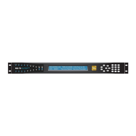
Chapter 1 - Product Introduction Front Panel The front panel LCD and keypad can be used to configure and monitor your device. -
Page 9: Front Panel Lcd
Front Panel LCD 1) Feedback State: There are several quick view menu screens available when in regular feedback state. You can view any of these quick view status screens by using the up and down arrow buttons. 2) Disabled Product State: When the product is in a disabled state, the LCD will relay the... -
Page 10: Transport Led Indicators
following information. This state is generally only used when a factory restore is performed. If that is the case, note that all of the configurations have been returned to factory defaults including Network configurations. To reapply network configurations simply press the Down arrow when in this state to navigate through the network menu. -
Page 11: Controls
Indicator Function Alarm Off - No system alarms. On - System alarm. (NTP or FAN alarm) BISS Off - Decryption configuration is turned OFF On - Decryption configuration is set to BISS1 or BISSE Link Off - Network communication link not detected On - Network communication link detected Busy Off - No network activity... -
Page 12: Front Panel Menu Structure
Allows selection of a service from a list of ALL ASI RF1 RF2 IP services per input. Decode First Found Allows you to configure the RD-70 to ASI RF1 RF2 IP decode the first valid program found on any input. RF Rx Menu (ADV Advanced / PRM Premium) - Page 13 2.15GHz. The value entered in this field is used with the Local Oscillator frequency to calculate the Downlink frequency using the following rules. If Downlink < Local Oscillator, then Downlink - Local Oscillator = │L-Band│. If Downlink > Local Oscillator, then Downlink - Local Oscillator = L-Band Modulation Allows the selection of the mod type.
- Page 14 QPSK-1/2 8PSK-5/6 QPSK-2/3 8PSK-8/9 QPSK-3/4 8PSK-9/10 QPSK-5/6 8PSK_AUTO* QPSK-6/7 16QAM-3/4 QPSK-7/8 16QAM-7/8 QPSK-1/4 16APSK-2/3 QPSK-1/3 16APSK-3/4 QPSK-2/5 16APSK-4/5 QPSK-3/5 16APSK-5/6 QPSK-4/5 16APSK-8/9 QPSK-8/9 16APSK-9/10 QPSK-9/10 32APSK-3/4 QPSK_AUTO* 32APSK-4/5 8PSK-3/5 32APSK-5/6 8PSK-2/3 32APSK-8/9 8PSK-3/4 32APSK-9/10 Symbol Rate The number of symbols transmitted per second. Range can be determined by The amount of data per symbol is dependant feature key.
- Page 15 demodulators. AUTO is only available in DVB-S. Pilot DVB-S2 allows the option of inserting bursts of pilot tones that are very robust and prevents the carrier recovery system from failing prematurely. However, when pilots are enabled, the total data rate throughput is reduced by approximately 3.0%.
-
Page 16: Rf Rx Menu (Lb L-Band)
Select Allows user to load profile from list. Press <select> then <up> and <down> arrows to list profiles. press <enter> to load selected profile. Delete Allows user to delete profile from list. Press <select> then <up> and <down> arrows to list profiles. - Page 17 Local Oscillator = │L-Band│. If Downlink > Local Oscillator, then Downlink - Local Oscillator = L-Band Acquisition Acquisition Range is defined as the range of 0 - 5MHz Range frequencies that the tuner will scan in order to achieve carrier synchronization. Allows the operator to select the range of frequencies that the RF tuner will sweep through to acquire the carrier.
- Page 18 quickview menu, but a detailed list of further information can be found in this menu.
-
Page 19: Ip Rx Menu
IP Rx Menu Item Function Options Multicast RX IP Multicast IPA sets the multicast receive 0.0.0.0 - Group IP address. IP Multicast receiving is 255.255.255.255 supported from compatible streamers. The range of the multicast group IP is 224.XXX.XXX.XXX to 239.XXX.XXX.XXX - XXX represents any number 0 through 255. -
Page 20: Video Menu
value is set too low, the multicast receive may timeout during normal reception if the packet transmission is bursty. Multicast Error Multicast Error Recovery sets the timeout 33 - 600000ms Recovery value for recovery of multicast receive after 10000ms (default) decoder error condition is detected. - Page 21 3G Mapping SDI 3G Level controls the Level SDI mapping of the 3G-SDI signal when decoding 1080P50, 1080P59.94 and 1080P60 streams. The 3G-SDI signal can be mapped to Level A or Level B Dual Link. The mapping is individually configurable for each set of outputs (SDI and SDIALT).
- Page 22 IN signal Horizontal Horizontal adjustment defines 0 - 2200 Adjust the difference in the SYNC IN HSYNC and output HSYNC. Typically, this should be in the range of 0 to +1 line in clocks. For example, a 1080I output could be adjusted from 0 to 2200.
-
Page 23: Audio Menu
PID's to audio engines PMT ORDER upon stream acquisition. This setting determines if the audio assignment should be done in PID Ascending order, the Adtec default, or PMT order. Some legacy IRD's use PMT order. Audio Sync Audio Sync Mode determines PROFESSIONAL (default) - Page 24 DolbyD Configures the audio engine to PASSTHRU (default) Mode Pass-through ( COMPRESSED ) DECODE - STEREO* or decode ( 2/0 STEREO ) if a Dolby Digital AC3 PID is detected for the selected Audio input. Mpeg1Layer2 always decodes, and LPCM / Dolby E always Pass-through, regardless of this setting.
- Page 25 SDI pair AUDIO3, Route Audio 3 to the selected SDI pair AUDIO4, Route Audio 4 to the selected SDI pair AUDIO5, Route Audio 5 to the selected SDI pair AUDIO6, Route Audio 6 to the selected SDI pair AUDIO7, Route Audio 7 to the selected SDI pair AUDIO8, Route Audio 8 to the selected SDI pair...
-
Page 26: Vbi Menu
VBI Menu Item Function Options SMPTE 2038 Configures the SDI ANC passthrough feature. Pass-through SDI Line Configures the SDI ANC line output of AFD ( 0 - Disabled Number SDI Output Port 1 and 2 ) 7 - 22 SDI Alt. Line Configures the SDI Alternate ANC line output of 0 - Disabled Number... -
Page 27: Cas Menu
CAS Menu Item Function Options Mode Configures the current decryption setting. BISS_1 BISS_E_USER_ID_ON BISS_E_USER_ID_TW Clear Session Word The session keys used for decryption. user-defined using the [MODE BISS_1] uses a 12-digit numeric keypad hexadecimal Clear Session Word. Encrypted Session The 16-digit hexadecimal Encrypted user-defined using the Word Session Word for use with BISS_E modes. - Page 28 IP Tx Menu Note: this is a parallel menu. It has four indices. Use the left or right arrows to navigate to desired index. Item Function Options IP Tx 1 - 4 Mode Enables IP Egress. SEND Tx IP Address The IP Address of which the Multicast or user-defined;...
- Page 29 that can be recovered Note: The product of FEC L and FEC D cannot exceed a value of 100 FEC D defines latency involved in burst recovery 4-20 Allows the operator to sets the TOS bits 0 = Normal service in the IPv4 header of the TSoIP payload 2 = Minimize monetary cost...
-
Page 30: System Menu
System Menu Login Units ship with the front panel logged in by default. If you become logged out and are prompted for a password, use the following key sequence for access. note: The key sequence can be remembered by using the word ‘USER’ for ‘ U p , S e lect, E... - Page 31 Item Function Options Network Menu Ethernet IP Address This is the address of your device user-defined using the numeric on your network specific to the keypad Ethernet Port. Default is 192.168.10.48 Ethernet Mask Defines the unit relative to the user-defined using the numeric rest of your network.
- Page 32 Protocol (SNMP) feature. We support SNMPv2c. Read-only The Simple Network Management user-defined using the numeric community Protocol (SNMP) Read-Only keypad Password. Default Value: "adtec" default: adtec Read-write The Simple Network Management user-defined using the numeric community Protocol (SNMP) Read-Write keypad Password.
-
Page 33: Com2
Com2 Item Function Options Com2 Settings RS-232 terminal monitor for 115200 8 1 NONE communicating with the 57600 8 1 NONE internal host motherboard for 38400 8 1 NONE diagnostics. 19200 8 1 NONE 9600 8 1 NONE Default is 38400 8 1 None Host Name Item Function... -
Page 34: Profile Menu
temporary key capable. Profile Menu Item Function Options Last Loaded Profile Displays the last profile loaded Select The select submenu lists all stored profiles and allows loading Save The save submenu saves a profile with a user designated name Delete The delete submenu deletes a profile from the available list... -
Page 35: Back Panel
Back Panel Connector Description Processor Power 1 & 2 Redundant AC Power, Standard 3 pin computer power plug (Auto range 70-240 VAC Input) GigE UDP or RTP multicast transport ingress port (SMPTE 2022) COM2 API Serial Communication Interface ** COM1 Serial Port Used for Troubleshooting (Terminal) Ethernet 10/100 base T ethernet interface (Monitoring/Management) -
Page 36: Db9-M Analog Audio Output Pinout
ASI/SDI In 75 Ohm terminated BNC input. SDI input features are not active at this time. x3 ASI OUT x3 75 Ohm BNC ASI output per EN5000839 Sync In Standard analog video sync separation for NTSC, PAL, 480I/P, 576I/P, 720P, and 1080I/P/PsF from Composite Video (CVBS). Bi-level &... -
Page 37: Com1/Com2 To Db9 Serial Adapter
COM1/COM2 to DB9 Serial Adapter The COM1 and COM2 port is an industry standard RS-232 DTE device on RJ45/RJ48. Units ship with RJ45 to DB9 adapters that are pinned per the following. DB9 PIN DB9 Function RJ45 Pin RJ45 Function Carrier Detect (CD) No Connect / Carrier Detect (DCD) Receive Data (RXD) - Page 38 Data bit 0 (input) No Connect 5VDC +5V DC ground No Connect C hapter 2 - Getting Connected Introduction to the Control Application A web-based control software application comes pre-installed on the RD-70. Compatible browsers Firefox (recommended) MS Internet Explorer Safari Chrome...
- Page 39 Ethernet Access To begin, you will need to connect to your RD-70 via Ethernet directly, or by adding the RD-70 to your local area network. The default address for all Adtec devices is 192.168.10.48. To connect directly to the device, make sure that your computer and the device have IP addresses within the same IP class range.
- Page 40 DVB-S / DVB-S2 AUTO Modes (LB option) The RD-70 with L-Band demodulator (LB) option supports automatic detection of modulation type and symbol rate on two RF inputs. In fully automatic mode, the minimum configuration requirement is L-Band frequency. The demodulator is running in fully automatic mode when the type is set to ‘AUTO’...
- Page 41 Click the Apply button to save information to the currently running configuration ● Click the ‘Create RF Profile’ button next to the respective tuner that is desired to be ● stored. Name the RF Profile and click OK. Please note that only Alphanumeric and ●...
- Page 42 If packets are lost or received out of order, service anomalies will occur. The RD-70 supports up to 100Mb/s when a 7 DVB Packet payload exists for each UDP packet.
- Page 43 The TCP mechanism when combined with large IP receive buffers can be more forgiving with packet loss, jitter, and out of order packets. The RD-70 supports up to 15 Mb/s when a 7 DVB Packet payload exists for each TCP packet. Multicast is n ot supported with TCP streams.
- Page 44 2000 is a common port to start with. Please verify transmitter port configuration. Choose the IP Rx ‘Connector’ dependent upon your network setup. Adtec recommends using the GigE port for all IP receptions.
- Page 45 Dolby E, Dolby D, LPCM, and Mpeg 1 Layer 2 As of 0.01.00 firmware, the RD-70 supports 16 channels of SDI embedded audio output with support of up to four audio pass-throughs, up to 8 pairs (sixteen channels) of aligned Mpeg 1 Layer 2 audio, and up to 8 pairs of Dolby Digital decoding.
- Page 46 AFD carriage can be carried within a transport stream as a unique ANC PID (ancillary pid), within the video elementary stream as SEI data (H264), or user data (MPEG2). The RD-70 does not support AFD via an ANC PID at this time.
- Page 47 The RD-70 AFD implementation preserves the native AFD code from the video elementary stream and is inserted into the SDI ancillary data output on DID/SDID 0x4105. The SDI output is not modified in anyway based upon this data. SDI line number for AFD carriage is configurable via the VBI tab.
- Page 48 Genlock System The RD-70 can synchronize its SDI and CVBS outputs to an external sync signal using the SYNC IN input and the Genlock control system. The SYNC IN input signal's frame synchronization is used to generate SDI and CVBS output pixel clocks, frame synchronization and audio clocks that are locked to the SYNC IN reference.
- Page 49 determines if the ASI output should mirror the selected input (OFF), thus preserving any encrypted streams or if it should be decrypted / free to air (ON). TS Out Decrypt should be set to OFF, the default configuration, if the IRD is to be used in a confidence decode / turn around application.
- Page 50 The Adtec RD-70 also has the ability to route Inputs to Outputs, such as route ASI Input to IP Output and/or RF Input to ASI Output. The RD-70 does n ot support multiplexing of the inputs. Each IP destination also has unique filtering capabilities. A block diagram of the...
- Page 51 Input to Output Routing and Filtering The SVC-FILTR key must be enabled to configure Service Filtering. When filtering is enabled, a maximum of 5 programs are allowed on any given output. If filtering is disabled, all programs available on the input are available on the output, ie, unit is in service pass through mode.
- Page 52 Firmware Upgrade via Web User Interface Periodically, we will provide firmware updates to our products via our website. (http://www.adtecdigital.com) To upgrade your device, download the firmware file from our website and store it locally. Login to the web-based application and navigate to the Upgrade >...
- Page 53 Demodulator Firmware Upgrade via Web User Interface In some cases, Adtec may provide a modulator or demodulator firmware upgrade. These are handled separately than standard product firmware upgrades because they can take longer than a product firmware update and should be planned during maintenance windows.
- Page 54 The above example shows a PRM demod running demod version 1.17. In this case, a 7044AB firmware file name is required to update this demodulator. If a demodulator firmware is provided for any reason, please make sure the firmware type provided matches the hardware type of the unit it is being installed on.
- Page 55 For those times when using the web user interface is not convenient, you can upload the firmware file via ftp and then extract and select into it via Telnet. File Transfer Protocol (FTP) FTP connections can be made to the Adtec device using any ftp client. Host: <ipa of the unit> Default Username: adtec...
- Page 56 When prompted for a username, enter adtec. When prompted for a password, enter none. Once you see "User 'adtec' connected", the session is open and you may issue API commands to the unit. To extract and select into the new firmware version you have uploaded, issue the following commands.
- Page 57 In Field Feature Upgrades Unit features can be upgraded in the field via the web user interface. Keys can either be temporary (feature will stop working after a set amount of time) or permanent (key is good for the life of the product). To purchase a permanent key, please provide your unit serial number and product ID from the Upgrade ->...
- Page 58 Temporary Key Instructions If a temporary key is provided, it will be in the form of an email attachment or file. Temporary keys are n ot entered through the ‘Input Key’ button. Instead, they are transferred to the unit through the use of the file transfer utility via the ‘Upload’ button. The ‘Upload’...
- Page 59 Feature Key Descriptions Base Unit Keys PdRD7X - This is the product key to determine product type MP2-BASE-D - Adds Mpeg2 4:2:0 and 4:2:2 decode capability MP4-CHR-420D - Adds Mpeg4/AVC/H.264 4:2:0 decode capability MP4-CHR-422D - Adds Mpeg4/AVC/H.264 4:2:2 decode capability 10BIT-D - Adds Mpeg4/AVC/H.264 10Bit decode capability 1080P-DEC - Adds 1080P50/59.94 decode capability AUD-EXP - Adds support for 4 additional pairs of audio decoding...
- Page 60 know their rights. We protect your rights with two steps: (1) copyright the software, and (2) offer you this license which gives you legal permission to copy, distribute and/or modify the software. Also, for each author's protection and ours, we want to make certain that everyone understands that there is no warranty for this free software.
- Page 61 include anything that is normally distributed (in either source or binary form) with the major components (compiler, kernel, and so on) of the operating system on which the executable runs, unless that component itself accompanies the executable. If distribution of executable or object code is made by offering access to copy from a designated place, then offering equivalent access to copy the source code from the same place counts as distribution of the source code, even though third parties are not compelled to copy the source along with the object code.
- Page 62 BEING RENDERED INACCURATE OR LOSSES SUSTAINED BY YOU OR THIRD PARTIES OR A FAILURE OF THE PROGRAM TO OPERATE WITH ANY OTHER PROGRAMS), EVEN IF SUCH HOLDER OR OTHER PARTY HAS BEEN ADVISED OF THE POSSIBILITY OF SUCH DAMAGES. END OF TERMS AND CONDITIONS How to Apply These Terms to Your New Programs If you develop a new program, and you want it to be of the greatest possible use to the public, the best way to achieve this is to make it free software which everyone can redistribute and change under these terms.
- Page 63 Appendix B - Technical Specifications Base Model (RD70-XX) Inputs DVB-ASI Use: Input available for Decode or Pass to ASI outputs. Standard: Asynchronous Serial Interface per EN500083-9 Input Rates: DVB-ASI 210Mb/s for free-to-air 188/204/208 Byte Transport streams (SPTS and MPTS). If TSO (TS Out Decrypt) option is OFF and transport stream contains BISS encrypted programs, up to 164Mb/s at this time.
- Page 64 SDI Ancillary support for Closed Captioning, AFD and Teletext SDI Ancillary data and OSD overlay have unique configuration for each SDI bank Connector: Three BNC (75 Ohm), One SFP note*: 3G-SDI Outputs have selectable Level A and Level B Dual Link output control to retain interoperability with other third party 3G devices.
- Page 65 Baud Configuration: 115,200 bps 8 data bits 1 stop bit no parity Ethernet Port Use: ethernet port used for network control, but can be used for IP receive/transmit Format: Ethernet 10/100BaseT Communication Methods: WebUI, SNMP, Telnet, XCP Connector: 8 pin RJ45 DB9 Parallel Port Use: DB9 parallel port used for custom triggering / integration Connector: DB9 Male...
- Page 66 Physical / Environmental 1 RU - 18D X 19W X 1.65H Weight – 9-14lbs. Dependent on RF Option Power Input Voltage: 100VAC - 240VAC 50/60Hz Operational - Ambient operating temperature: -20C to 40C. - Ambient storage temperature: -30C to 80C. - Non-condensing relative humidity range: 30% to 85% Certification / Compliance RoHS Compliant...
- Page 67 L-Band Demodulator (LB option) note: Software keys are required to unlock full hardware support. RF Inputs: Dual RF inputs capable of simultaneous lock EN 302 207 and EN 300 421 compliant for single and multi-stream Modulation Scheme support: QPSK / 8PSK / 16APSK / 32APSK Long and Short frame support Supported Roll-off: 5%, 10%, 15%, 20%, 25%, 35% Supported Code Rates:...
- Page 68 Premium Demodulator (PRM option) note: Software keys are required to unlock full hardware support. Modulation Scheme support: QPSK / 8PSK / 16APSK / 32APSK Supported Roll-off: 5%, 10%, 15%, 20%, 25%, 35% Supported Code Rates: DVB-S QPSK: 1/2, 2/3, 3/4, 5/6, 6/7, 7/8 DVB-S 8PSK: 2/3, 5/6, 8/9 DVB-S/SNG 16QAM: 3/4, 7/8, (AUTO) DVB-S2 QPSK: 1/4, 1/3, 2/5, 1/2, 3/5, 2/3, 3/4, 4/5, 5/6, 8/9, 9/10...
- Page 69 Appendix C - Adtec Digital Support & Service For Customer Service contact information, SLA Information, policies and more, please visit the support site at: h ttp://www.adtecdigital.com/support...
Need help?
Do you have a question about the RD-70 and is the answer not in the manual?
Questions and answers